Upcoming EPA regulations open the door for innovative methane detection technologies
Reducing methane emissions from the oil and gas industry is a cornerstone of the Biden administration’s climate policy. The EPA proposed regulations in November 2021 to reduce methane emissions from the onshore upstream and midstream oil and gas industry by 70%. The EPA expects to achieve an annual reduction of 4 million metric tons of methane emissions in 2026 by implementing this regulation. By comparison, the reduction is equivalent to permanently removing about 25 million cars from the nation’s streets. It has a far bigger climate impact than the forecasted adoption rate of electric cars in this decade, in the U.S.
The regulations are broad in scope and will have a major impact on upstream and midstream operations. Key elements are a dramatic increase in requirements for optical gas inspections (OGI), as well as far-reaching requirements for facility upgrades to minimize emissions. A particular focus is on central facilities and tank batteries, as malfunctions of tanks are a major source of emissions. At the same time, the proposed rules, for the first time, introduce a new regulatory pathway for deploying innovative methane detection technologies, such as airborne imaging surveys and locally installed, continuous optical gas imaging cameras.
Broad coverage of upstream and midstream sectors. The proposed regulations cover the entire upstream and midstream oil and gas sectors, from wellhead to gas plants, including all facilities at oil and natural gas well sites; tank batteries; gathering and boosting compressor stations; natural gas processing plants; and transmission and storage facilities.
They also cover well completions during flowback and include provisions to potentially be expanded to abandoned well sites. Both existing and new sites are covered by the rules, and both methane and volatile organic compound (VOC) emissions are regulated. EPA estimates that about 280,000 oil and gas wells (including central processing facilities and tank batteries); over 3,500 gathering and boosting stations; 2,000 natural gas processing plants; and 1,900 transmission and storage compressor stations are incrementally impacted—that is, they will fall under the rules for the first time or requirements are increased. Parallel rules from PHMSA are expected to cover transmission and distribution pipelines, and associated pipeline facilities, as well as some gathering pipelines. Specific areas that are regulated are listed in Table 1.

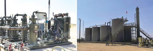
Extensive installation requirements. One of the most far-reaching aspects of the rules is a dramatic expansion of the number of sites with oil, condensate and produced water tanks that will require installation of a vapor recovery unit (VRU), with sales line tie-in or flare. The authors estimate that the industry will have over 10,000 sites that need installations. A typical VRU setup is shown in Fig. 1.
Current VRU requirements kick in for tanks, when potential VOC emissions from a single tank exceed 6 tons per year (tpy). A tank battery with, for example, 16 storage vessels, can currently emit far more than 6 tpy, as long as each tank stays below the 6-tpy limit. With the new rules, the 6-tpy threshold for VOCs applies to the entire tank battery, where storage vessels are linked together. Moreover, an additional limit of 20 tpy of methane from the entire tank battery is introduced. Converted into customary industry units, this represents an emissions limit of 0.3 Mcfd for VOCs and 2.7 Mcfd of methane for the entire tank battery, assuming constant emissions. For comparison, a single, open thief hatch can easily emit 25 Mcfd of VOCs and methane combined. In practice, no meaningful emissions from tank thief hatches or Enardo valves will be permitted.
Vapor recovery units need to be designed and operated to handle peak production capacity reliably and, in many cases, also need to cover produced water tanks. This can be problematic on new wells, as their initial production rates are far higher than they will be in subsequent months. Smaller and older sites with uncontrolled tanks will be required to install VRUs. Similar rules are in place in Colorado and New Mexico, and are being enforced by regulators issuing fines of up to $45,000 for every day a thief hatch is found to be left open.
Another key aspect is the phasing out of gas-powered pneumatic controllers, including low-bleed models and replacement with no-bleed controllers, also known as Scope 1. Multi-year implementation timelines are proposed for existing facilities. Again, the proposed EPA rules are following recently enacted regulations in Colorado, where pneumatic controllers are currently being phased out. The proposal also prohibits flaring of associated gas from oil wells, unless the operator shows that a gas sales line is not accessible.
More optical gas inspections required. OGI inspection requirements and intervals for upstream sites are currently based on the expected production volume. EPA is making a major change by focusing on the number of pieces of equipment installed on a site, irrespective of production volumes. The rationale for this change is that surveys have shown that site emissions are primarily correlated to the number and type of equipment that can potentially fail and emit, not to the production volume.
The “potential to emit” will have to be calculated for every site, based on equipment count and emissions factors. In practice, almost all sites that consist of more than a wellhead will fall under one of the several OGI inspection requirements. EPA estimates this to be about 300,000 upstream sites—with the remainder being marginal production sites with single wellheads. In addition to the number of sites covered, the frequency of inspections is also increased. All of these sites will require a full handheld OGI inspection four times a year—a major increase from the one to two times per year under current rules.
Detailed requirements on the training of handheld OGI camera inspectors are also being introduced, providing consistency in reporting and subsequent repairs. Minimum training levels will have to be demonstrated; a senior OGI inspector is required to oversee and check the performance of more junior operators, and frequent add-on training is required, including performance tests for OGI operators. The method by which manual surveys are conducted is much more prescribed, with new minimum dwell times for a handheld camera on each piece of equipment, likely lengthening the time it takes to complete a manual survey.
Documentation requirements for OGI surveys will be stepped up significantly, and operators will need to demonstrate that they performed all surveys according to the new regulations. In practice, the conduct of OGI surveys according to regulations may be met by time-stamped GPS tracking of the path taken by every OGI operator, for every survey, at every site. The oil and gas industry will likely have to hire and train thousands of additional OGI inspectors to meet the requirements of the regulations.
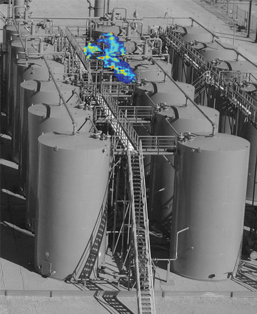
Emissions detections at tanks trigger a root cause analysis. A very impactful change is the broadening of what equipment is to be surveyed and what actions are to be taken. Specifically, tanks have to be surveyed from close up (i.e. on top of the catwalk, not from the bottom looking up). If any emissions are found, a root cause analysis needs to be conducted, and results are to be documented, Fig. 2. Gas collection systems are expected to be completely gas-tight. The requirement for root cause analysis is likely to create a very significant additional workload for upstream field staff. In a recent field study from TRP Energy at upstream sites, tank-related emissions have been found to be the major source of emissions.
Tank emissions are tied to changing process conditions and are, therefore, highly variable and often intermittent. TRP found that the root cause is usually difficult and time-consuming to discern. Tanks are part of a complex connected system of processes and controls, and any aspect of these systems can cause emissions to come from tanks. Root causes range from suboptimal set-points for separator cycle times; sand entrainment in pipes leading to intermittent clogging; set-points for VRU pumps that are drifting outside the optimum range; to general maintenance problems and many others.
Methane detection technologies. A major innovation in the proposed regulation is a pathway to allow for the use of new and innovative technologies to meet regulatory requirements. Specifically, “alternative screening technologies,” such as airplane surveys, continuous point sensors and continuous OGI cameras, can be used to reduce the required number of manual/handheld OGI inspections. In the proposed regulations, operators can choose to either conduct handheld OGI four times per year or to conduct handheld OGI once per year and an alternative screening at least six times per year. The rationale behind this approach is to focus screening on “super-emitters,” such as open thief hatches, unlit flares, open by-pass valves, blow-downs and malfunctioning VRUs. The key insight is that finding and fixing big leaks faster is what counts most to reduce emissions.
This is backed by recent large-scale studies from the Collaboratory to Advance Methane Science (CAMS), an industry research consortium funded by Exxon, Chevron, Cheniere, Williams and others. CAMS recently published a plane-based survey of 1,450 facilities in the Permian basin. Key results are that 6% of facilities accounted for almost all emissions, and emissions from tanks were the largest category, with 40% of the total. Equally important, the study found that more than half of these emissions could not be detected on a second overflight, indicating that they are intermittent.
In a major regulatory shift, the EPA is now focusing on these super-emitters and has set a limit of 10 kg/h methane as the detection limit for these screening technologies. EPA states that screening can be performed with any technology that can detect emissions at this limit, including airborne imaging surveys, continuous point sensors and continuous OGI cameras.
Aerial imaging surveys and continuous point sensors are promising. Airborne imaging surveys are a promising solution for this alternative regulatory pathway. Exxon conducted long running field studies of airborne imaging surveys in the past years and concluded that airborne imaging surveys detect more emissions than OGI inspections, because they detect super-emitters fast. Continuous monitoring solutions are expected to perform even better, as they measure every day and not just occasionally.
Few details are included in the current draft text on how to specifically regulate innovative solutions like airborne surveys and continuous monitoring in practice. Instead, EPA is asking industry and the public to propose specific regulations to ensure super-emitters are reliably detected.
A key aspect to be addressed is the intermittency of emissions. An airborne imaging survey may catch tank emissions, but by the time a ground crew conducts a follow-up OGI investigation, these emissions are not present any more. A root cause analysis will likely have to be conducted every time emissions are found, which may quickly become costly and time-consuming. Moreover, so called “methane slip” from incomplete combustion at upstream and midstream compressor stations produces a permanent plume of emissions. While these emissions are technically not avoidable and in compliance with regulations, they may obscure actual super emitters or they could be misidentified and trigger unnecessary onsite investigations (false alarms).
Continuous point sensors have been tested by multiple operators in the past years. In concept, they are an excellent solution, because they detect super emitters fast. In practice, they still have to address a number of challenges. Emissions from points higher up, such as tank thief hatches or pressure relief valves at separators, tend to often be missed by point sensors as emissions blow over the installed height of point sensors and are, therefore, not detected. The METEC test facility at Colorado State University conducted a five-month test of point sensors and continuous OGI cameras, with hundreds of controlled gas releases during 2021 under the new ADED blind test protocol for continuous monitoring solutions. The results were presented this past December at the AGU conference in New Orleans. The authors concluded that the configurations of point sensors tested missed about 50% of emissions, irrespective of how large emissions were, because the plume never reached the sensor.
In contrast, a continuous OGI camera tested in parallel with the same gas releases was able to detect all emissions larger than 3.5 kg/h methane, as well as part of the emissions down to 0.25 kg/h. Follow-up work is being conducted to study installing taller mounting poles, with multiple point sensors at different heights on each pole, in order to improve the detection rates for tank emissions while maintaining coverage for lower-placed emissions sources. Additional challenges for point sensors involve distinguishing between routine emissions on a site, such as methane combustion slip from compressors and super emitter events. If the alarm level of point sensor networks is set too strictly, there is a risk of producing a lot of false alarms and expensive root cause investigations with handheld OGI on-site that turn into a ghost chase. If the alarm level is set too loose, it may miss too many super-emitter events of 10 kg/h or higher.
Continuous OGI camera solution. Continuous OGI cameras, like those available from Kuva Systems, address the challenges of point sensors, because they produce images of emission events directly at the source of the emissions and do not rely on wind to bring emissions to the camera detector. Continuous OGI cameras are typically mounted on a single pole and placed near the center of a site. They can then be rotated 360° for full site coverage. Images allow pinpointing of emissions to a specific piece of equipment or a specific component. Visual review of an image of emissions allows to differentiate (for example) between permitted methane slip from compressors and abnormal emissions, without the need to access a site or for follow-on inspections. This has proven to be highly effective at determining the cause of process-related emissions when the time-stamped images are correlated with process SCADA data, as indicated further below.
Continuous OGI cameras also provide additional value, as they go beyond the initial detection step and enable remote root cause analysis. Users of the continuous OGI camera are receiving time-stamped images of emission events when they occur. These images are then correlated with SCADA data of other site parameters, such as pressure, temperature, flowrate, tank level, motor or compressor settings.
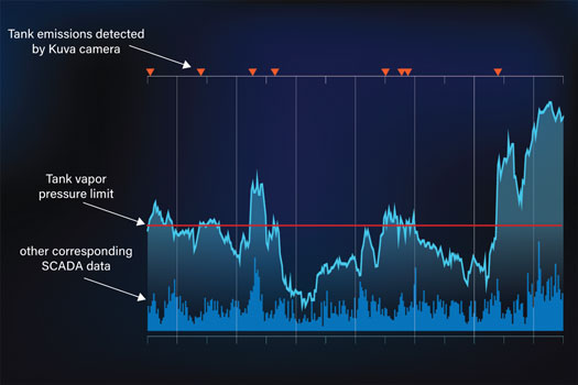
Figure 3 shows an example where intermittent tank emissions were detected for a specific tank in a larger battery. By correlation with tank vapor pressure levels at this tank, it was found that the set-point of the VRU was too low, thereby not evacuating fast enough and causing intermittent emissions.
By correlation of the start and stop times of emissions events with SCADA data, Kuva’s customers find root causes without an on-site investigation. In some cases that involve set-points of equipment, the root cause could even be eliminated by simply changing set-points and without any need for a site-visit. Another benefit of continuous OGI cameras is that they can be used to validate repairs, once they have been conducted, again replacing the need for an expensive OGI inspection. Moreover, because they operate continuously, installed OGI cameras and the associated cloud solutions are ideal for generating the required documentation to demonstrate ongoing compliance to regulators.
Major cost reductions. A key aspect of any advanced monitoring solution is to avoid false positive alarms. The Kuva camera solution participated in the above-mentioned blind testing at METEC and was found to produce zero false positive alerts during the entire five-month test period. Continuous OGI cameras were pioneered over the past decade for use in refineries, however they proved to be extremely expensive. Continuous OGI technology has improved steadily since then and has fallen dramatically in price. A continuous OGI camera is available today for less than 10% of what it would have cost a few years ago, making continuous OGI an attractive value proposition for upstream and midstream operators.
ESG strategies. Many publicly listed oil and gas companies have positioned themselves as ESG leaders in the industry, based on methane reduction efforts that go beyond current requirements. The EPA proposal dramatically increases the baseline for methane reduction, so that environmental, social and governance (ESG) policies that tout “beyond compliance” actions will have to be revised. Companies will have to grade their efforts against the new rules.
With the upcoming regulations already requiring frequent OGI inspections at most sites, widespread installation of VRUs and the phase-out of gas-driven pneumatic controllers, a credible ESG strategy is expected to focus on the fast identification and repair of super-emitters. Innovative technologies are available today, and continuous monitoring with continuous OGI cameras is a clear path forward for the industry to demonstrate ESG leadership.
- Executive viewpoint: Methane monitoring goes digital (May)
- Drilling technology: Optimizing high-pressure pump performance with fluid end advances (May)
- John Henry vs the steam drill: Will the robots win? (May)
- Why oil and gas companies should invest in ruggedized edge computing (May)
- What's new in production: When everything is going wrong at the same time (April)
- Op-Ed: American energy faces attacks by European activist courts (April)
- Subsea technology- Corrosion monitoring: From failure to success (February 2024)
- Applying ultra-deep LWD resistivity technology successfully in a SAGD operation (May 2019)
- Adoption of wireless intelligent completions advances (May 2019)
- Majors double down as takeaway crunch eases (April 2019)
- What’s new in well logging and formation evaluation (April 2019)
- Qualification of a 20,000-psi subsea BOP: A collaborative approach (February 2019)

