Directional drilling advances deliver tight-cluster, extended-reach wells in unconsolidated sands

Advances in directional drilling, logging while drilling (LWD) and well placement technologies have helped offshore operators reach new production targets, enabling wellbores to be threaded through geologically complex reservoirs and located many thousands of meters from a production platform.
Reducing drilling costs and risks is particularly challenging when drilling long laterals into soft formations that contain unconsolidated sands. Such formations introduce the potential for significant sliding while drilling through the incline, and drag forces that might prevent the casing string from reaching its intended setting depth. Well integrity issues also include the risks of lost circulation, inadequate zonal isolation and wellbore collapse. Without a collaborative problem-solving approach between the operator and service companies, these challenges might lead to sub-optimal production rates or total loss of the well.
Addax Petroleum, an international oil and gas E&P company operating predominantly in West Africa, faced several such drilling and completion challenges in Cameroon, while attempting to deliver its first extended-reach, high-inclination well in 2013. Lost circulation in the 17 1/2-in. section of the well resulted in having to drill a sidetrack. The situation became more challenging in the 12 1/4-in. hole section, where the unconsolidated formation resulted in an inability to steer and hold inclination with the rotary steerable system (RSS).
Drilling of the remainder of the section continued with a mud motor, which resulted in a tortuous wellbore that hindered progress in subsequent sections of the well. Drag forces prevented the 9 5/8-in. casing from reaching bottom, and the casing shoe had to be set in the sand formation above the target depth. In addition, it was not possible to re-enter the 8 1/2-in. hole section, thus leading to an accidental sidetrack. The operator suspended operations in the well, to plan a re-entry route into the 8 1/2-in. hole section by sidetracking off a 9 5/8-in. whipstock.
After the operator conducted an internal study, reconsidering the formation pore pressures and fracture gradient values, the mud weight was adjusted, to control the overpressure shale zones and to avoid wellbore instabilities. The sidetrack was performed successfully to finish drilling the 8 1/2-in. section, and subsequently the 6-in. section, using the RSS without incident and ensuring wellbore stability.
Once the well was completed and brought online, production rates exceeded expectations. This success prompted the operator, in collaboration with the service company, to study and implement improved methods for drilling future extended-reach wells in the block, while avoiding the setbacks encountered in the first well.
COLLABORATIVE PLANNING
Over the next several months, the companies collaborated on the planning and design phase for the next set of wells. These, and all future wells, would have to be executed in a tight cluster from the same platform, a challenge exacerbated by the unconsolidated nature of the formation. As a result, development plans could not focus solely on the placement of the next well to be drilled, but would instead have to factor in the placement of all wells planned in the target area.
Drilling solutions, therefore, focused on maintaining well integrity and delivering a smooth wellbore. In addition, because all of the wells would be drilled near horizontal, at a 270° azimuth, any solution would need to reduce the ellipsoid of uncertainty (EOU) to avoid costly sidetracks and collisions with adjacent wells.
This collaboration continued during drilling, with frequent videoconferences between the operator’s geoscientists, petroleum engineers, and drilling engineers and the service company’s drilling services team. Members of the joint team, who were routinely in different offices or time zones, would collectively review survey data gathered from the various LWD, and survey tools deployed downhole for each section drilled. Because all meeting attendees were able to see the same data at the same time, they were able to make quicker, more informed drilling decisions for the next well section.
ADAPTING THE RSS
The first of the new wells was spudded in August 2015, and it soon presented the joint team with its first operational challenge—how to effectively isolate a lost-circulation zone while drilling a 26-in. section below the 30-in. conductor casing. The section was drilled with a jetting bottomhole assembly (BHA) that included a gyro-while-drilling package to provide the necessary directional control, and enabled 20-in. casing to be run to isolate the lost-circulation zone. This section was drilled successfully, and the lost-circulation zone cased off; however, the 20-in. casing did not reach section TD, leading to a 17 1/2-in. sidetrack. Lessons learned from the 26-in. BHA behavior, mud system design and trajectory profile were applied successfully to subsequent wells.
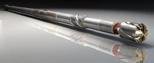
Based on the lessons learned from the first well in the campaign, the service company made fundamental changes to the design of the RSS. A 10-in. passive gauge PDC bit would be used, with the bit hydraulics modified to reduce jet impact forces and hydraulic horsepower per square inch acting on the soft formation. This was accomplished by increasing the bit’s total flow area to more than 2.0 sq. in., a condition that would normally result in a pressure drop that is too low to allow downlinking with the RSS.
This problem was resolved by redesigning the restrictor housing in the pivot stabilizer. The original design allowed for the restrictor housing to be placed on the fish neck side of the pivot stabilizer, which would create a problem when running the stabilizer in the soft formation. The restrictor housings were not long enough to fit flush against the face of the bit threads and generate a seal around the exterior of the housing. The design was modified to place the restrictor housing in the uphole section of the pivot stabilizer, which would guarantee a seal around the exterior of the housing and prevent wash below the housing. This modification also ensured that high-velocity flow was only directed onto a replaceable carbide nozzle fitted inside the housing.
The modified RSS was run successfully in the 12 1/4-in. section, with complete directional control and a shorter drilling time, compared to previous wells drilled from the same platform. This improvement is largely attributed to the ability to pump at a higher rate without the risk of washing the hole and inducing high sleeve rotation. The improved RSS avoided the need for a mud motor to finish the well, resulting in a smoother wellbore, without the need for sliding, and a more efficient means of reaching target depth (TD).
GEOSTEERING TO TARGET
A 6 3/4-in. RSS assembly was used to provide directional control while drilling the 8 1/2-in. pilot hole. The drilling plan called for the RSS to land the well into the formation and drill approximately 853 ft within the target formation. Directional corrections were made, using information provided by several LWD tools incorporated into the BHA, including the service company’s GuideWave azimuthal resistivity tool, a high-temperature, azimuthal, gamma ray sensor and a neutron density tool.

After reaching TD for this pilot hole section, a 6 3/4-in. PressureWave formation tester took pressure stations in the pilot hole target reservoir. The string was then pulled out of the hole, and the pilot hole was plugged back with openhole cement plugs. The same 6 3/4-in. BHA including the azimuthal resistivity tool, critical to ensuring an optimum relative well placement, was used to sidetrack off the cement plug and successfully land the well horizontally in the top of the target reservoir. The well-placement service started at 11,040 ft and landed the well into the target zone at 13,340 ft.
The final section was drilled, using a 4 3/4-in. RSS with an azimuthal-resistivity tool, to maintain optimal well placement within the reservoir. The well was drilled to TD at 14,160 ft, and the trajectory was fully maintained within the target zone and achieved
optimal placement.
This application marked the first use of the GuideWave technology in the country. The tool provided real-time inversion calculation and dip interpretation, which enabled the geosteering team to make directional adjustments by monitoring up/down resistivity curves and conductive bed responses. A proprietary inversion algorithm reliably calculated the distance between the wellbore and the top and base boundaries of the reservoir, which further enhanced the speed and precision of drilling-trajectory adjustments. In one instance, the directional signals provided an early warning that the wellbore was coming within approximately 3 ft of the top of the formation. The drilling team quickly corrected course, using the RSS, and successfully kept the wellbore in the target zone. The well was drilled in 63 days, less than half the 134 days required to deliver the previous well.
BUILDING ON SUCCESS
The lessons learned in the successful execution of the well influenced the drilling program for a third well, which would be the longest extended-reach well with the longest measured depth, to date, in the country. This new well was designed to land in the same reservoir as the previous one, but without using a pilot hole to identify the formation top.
Delivering the well with reduced EOU and no pilot hole required the introduction of another Gyro technology capable of reliably measuring inclinations exceeding 70°. The resulting surveys were spliced in with the other MWD surveys to provide a highly accurate data set and narrow the well’s EOU.
As the wellbore approached its target, the geosteering team reviewed the LWD and survey data and concluded that the well was coming in above the target and would land too high. The last survey showed an inclination of 84.31° and azimuth of 272.37° at 14,211.0 ft, MD. Based on these findings, the drilling team decided to hold inclination at 84°, and continue drilling until the wellbore contacted the target zone’s sand. This strategy helped to land the well on target, with minimal course correction required.
The well was drilled to a TD of 15,410 ft in 58 days. All five planned hole sections were drilled in just one run each, with zero hours of non-productive time (NPT) assigned to the drilling services team.
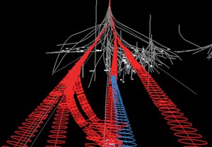
The drilling plan for the fourth well was initiated soon after reaching TD in the record-setting extended-reach directional well. The plan required positioning the new well laterally between the second and third wells drilled to hit a new geological target. Because of the relatively large EOU of the previous wells, the new well path’s EOU posed a challenge. The EOU could not be further reduced using conventional gyro and MWD survey technology; the error ellipses overlapped regardless of the well design. To mitigate the risk of well collision while drilling with overlapping EOU, a passive ranging service was employed to detect close approach with the existing wells and avoid collision.
The passive ranging service comprises two parts. The first is a pre-job model built from offset well casing profiles and the intended path of the planned well. The second part, real-time monitoring, is conducted from remote data centers in the UK and the U.S. to provide 24-hr coverage. The service can detect external magnetic interference on the MWD surveys before the interference affects the survey quality. If interference is detected, the third party conducts further processing to pinpoint the interference’s location away from the wellbore. This serves as a means of early detection that the actual well path is approaching an existing well, and the RSS can be directed to change course.
To help plan the fourth well in this campaign, the team sent the raw accelerometer and magnetometer readings collected from the MWD tools, along with the MD values of each survey, to the data centers for processing. The pre-job model concluded that any offset wells could be detected within 28 ft, with 99% certainty.
As a result of this analysis, the operator determined that the well could be drilled safely and effectively, provided adequate close monitoring of the activity was put in place to enable effective management during the execution. Weatherford management at a local, regional and global level also reviewed the well profile in detail, and concluded that the well could be executed in a safe and
low-risk manner.
Ultimately, the operator opted to complete the pilot hole in the well and forego the sidetrack to the primary target, eliminating the need for the ranging service. However, the information gained during pre-job planning for this well was invaluable to both the operator and the service company, and will be used as a model for future wells planned with close proximity to offset wells.
The fourth well was drilled successfully, with no excursions from the target reservoir, to an MD of 10,696 ft in just 21 days and with zero hours of NPT attributed to drilling services.
SUCCESS SPURS FUTURE PLANS
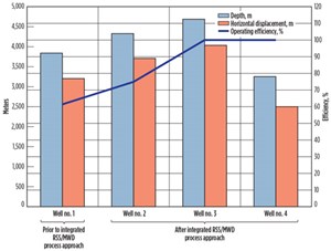
Improvements to the RSS and M/LWD technologies played a critical role in improving well placement for this drilling campaign. The lessons learned in each well influenced the drilling program for the next well, such that the number of drilling hours, number of runs and days to build each well dropped continually.
The three additional wells delivered significant production to the asset, with each well meeting or exceeding rate expectations. By maintaining each wellbore in the target zone without the need for sidetracks or sudden course corrections, the combined RSS and geosteering technologies helped reduce well risks and costs significantly.
Ultimately, this drilling program serves as a blueprint for designing and executing future extended-reach and close-proximity wells in West Africa. The successes realized with the integrated RSS, M/LWD and well placement service offering place the operator in a good position to replicate these results in future drilling campaigns. ![]()
- Coiled tubing drilling’s role in the energy transition (March 2024)
- Digital tool kit enhances real-time decision-making to improve drilling efficiency and performance (February 2024)
- E&P outside the U.S. maintains a disciplined pace (February 2024)
- U.S. operators reduce activity as crude prices plunge (February 2024)
- Drilling advances (January 2024)
- Driving MPD adoption with performance-enhancing technologies (January 2024)
- Applying ultra-deep LWD resistivity technology successfully in a SAGD operation (May 2019)
- Adoption of wireless intelligent completions advances (May 2019)
- Majors double down as takeaway crunch eases (April 2019)
- What’s new in well logging and formation evaluation (April 2019)
- Qualification of a 20,000-psi subsea BOP: A collaborative approach (February 2019)
- ConocoPhillips’ Greg Leveille sees rapid trajectory of technical advancement continuing (February 2019)


