Maximizing horsepower delivery in modern frac fleets through advanced pump design
ALEX FLORES, CHRIS DEGGINGER and TURNER HALL, GD Energy Products
Unconventional operations continue to evolve, as pressure pumping companies transition away from conventional diesel-powered equipment to achieve both economic and environmental benefits. Today, diesel-powered engines account for approximately 11% of those used in shale developments, while dual-fuel systems dominate the market at 52%. Electric-powered frac fleets represent 24% of deployed equipment, with natural gas engines accounting for 9%, and turbine direct drive systems making up the remaining 4%.
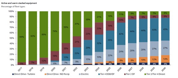
As alternative fueling technologies are adopted more widely, operators are reducing emissions while improving efficiency. However, these gains can be enhanced further by placing greater focus on how modern engines interact with the rest of the frac spread, particularly with high-horsepower pumps, Fig. 1.
THE DYNAMICS OF CHANGE
The drivers for moving away from diesel engines are clear. Lower fuel costs and reduced emissions are easy to quantify, making the economic and environmental benefits straightforward to justify. However, this is only part of the story.
Shifting to alternative fuel engines directly impacts the performance of the broader frac spread, and operators need to understand how these engines interact with the rest of the equipment.
Effective system performance depends on more than just engine type. Factors, such as torque characteristics, transmission behavior and pump design, must all be considered to ensure the system operates as intended.
Ideal driver performance delivers maximum brake horsepower (bhp) at optimum engine speed. This power is delivered to the pump input as torque (T) and speed (rpm). The pump translates this into fluid flowrate (gallons per minute [gpm]) at a given pressure (psi). The equation below illustrates this power conversion between the driver and the pump:
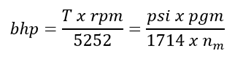
Where (T x rpm)/5252 describes how the driver delivers torque (T) and speed (rpm) to the pump, and (psi x pgm)/1714 x nm describes how the pump converts it to pressure (psi) and flowrate (gpm) and delivers it to the well.
Given that the end-user’s goal is to effectively pair the driver with the pump—translating available engine power (speed and torque) into maximum flow at treating pressure—one of the most critical considerations is how well the driver output aligns with the pump’s input requirements across the full operating range.
If this alignment is not achieved, it might not be possible to fully translate available engine horsepower into usable hydraulic horsepower at the well. In these situations, horsepower is effectively stranded within the drivetrain, limiting flow output and reducing overall system efficiency.
The pump’s gearbox ratio plays a key role in managing this relationship. It ensures that the pump operates at the optimal speed and torque for a given power source by converting higher engine RPM into the required pump input conditions. Properly optimized gearbox ratios help ensure available engine horsepower is converted into usable horsepower at the pump, while minimizing mechanical stress and inefficiencies. In addition, gearbox design can provide flexibility in driver input locations, supporting more efficient and adaptable skid layouts.
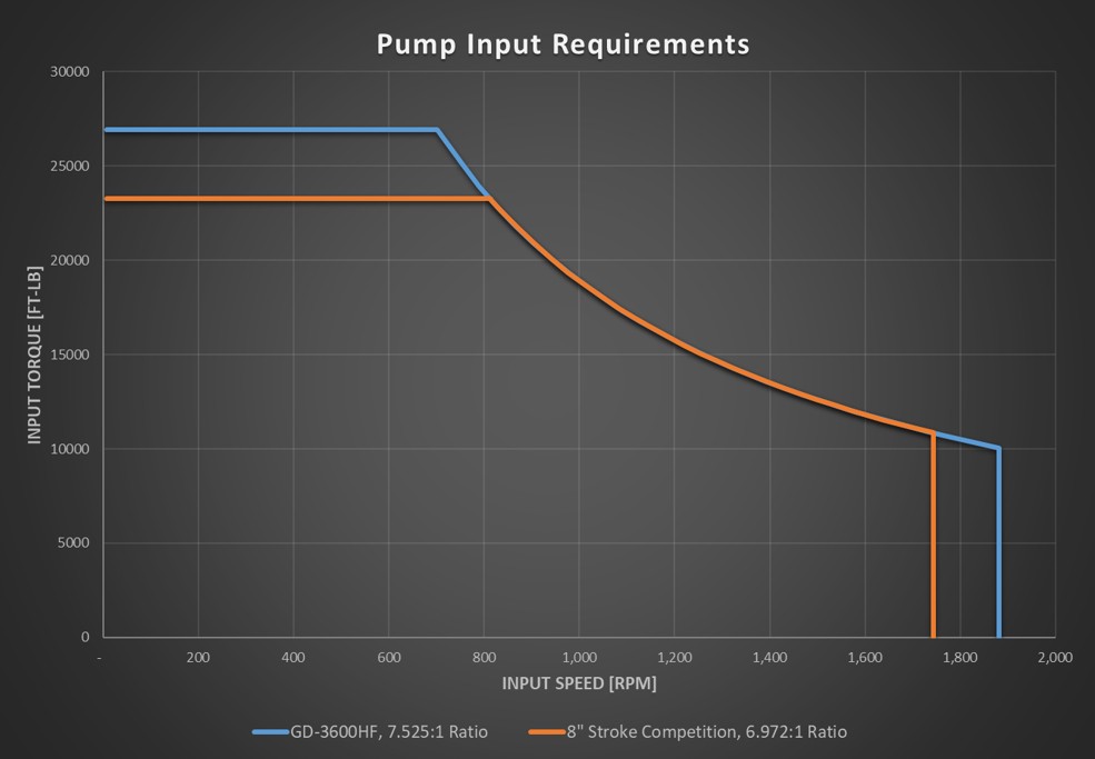
Differences in gearbox ratio influence the input speed and torque requirements of the pump, as shown in the comparison in Fig. 2.
Ultimately, the pump must deliver both the required pressure and flowrate into the formation. Flow, measured in gpm or gallons per revolution (gpr), is just as critical as pressure in achieving overall system performance and efficiency:
- Gallons per Revolution (gpr):

- Gallons Per Minute (gpm):
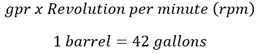
There are three ways to increase flowrate: increase the plunger area, increase the stroke length or increase the rpm (i.e., the speed of the pump).
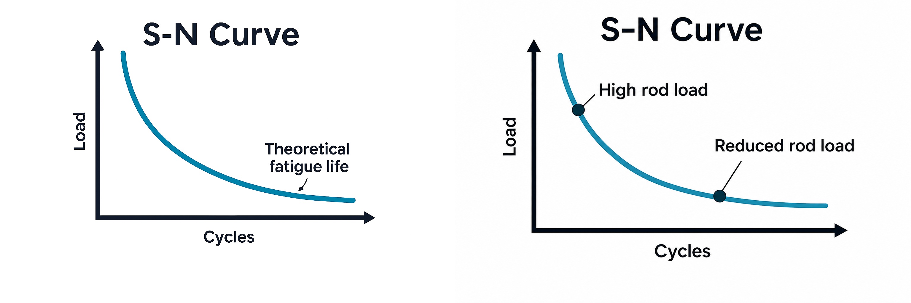
To fully realize performance gains at the pump, several additional factors must be considered. One of the most important is rod load—the force exerted on the pony rods during operation. While higher rod load is often associated with increased performance, that is not necessarily the case in practice. Excessive rod load accelerates wear on bearings, crossheads and pony rods, leading to more frequent maintenance and reduced equipment life. Over time, this can result in significant costs.
A more effective approach is to maintain a lower, balanced rod load. This reduces vibration and dynamic loading across the system, improving reliability while still enabling efficient flow and horsepower delivery. In simple terms, the highest efficiency is achieved when the pump operates at the lowest number of cycles per minute required to deliver the desired output, Fig. 3.
Increasing the plunger size intensifies the load on the power end drive line. Accelerated speed increases the rate of fatigue cycle accumulation on the power end. Employing a pump with a longer stroke than the standard 8-in. size, on the other hand, achieves the desired flowrate without exacerbating component wear.
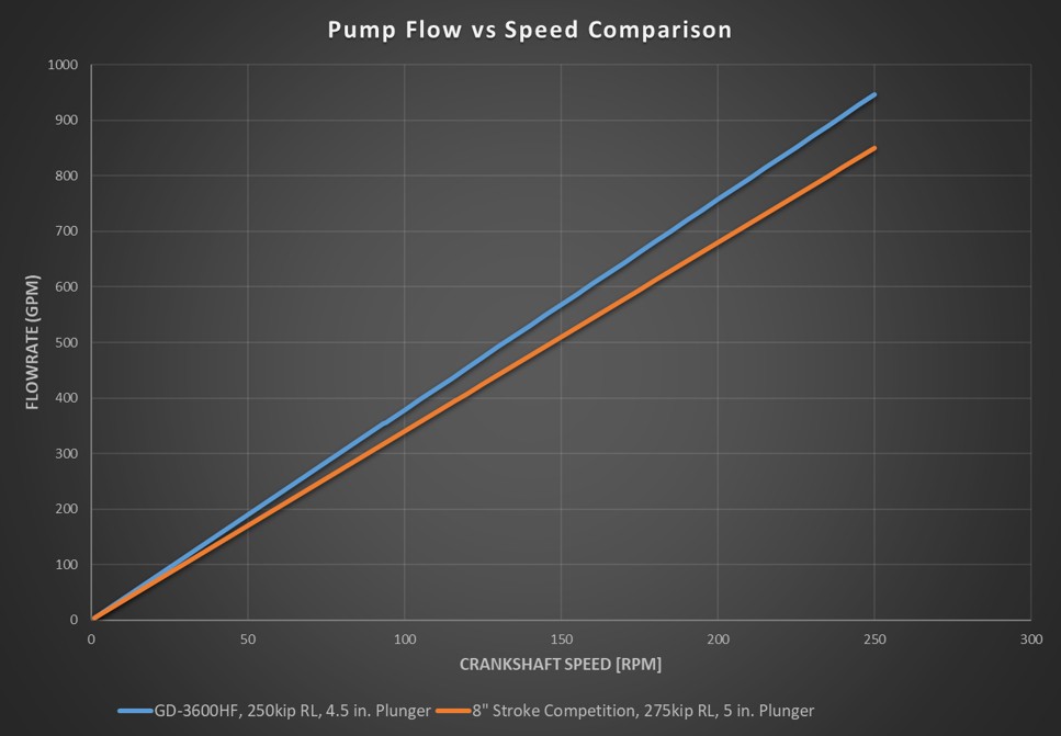
In fact, longer stroke length delivers improvements on multiple levels. An 11-in. stroke displaces up to 37% more fluid per revolution compared to an 8-in. stroke. With more fluid moved per cycle, the pump achieves the same output at lower rpm, reducing wear on critical components and extending service intervals. Simply put, the longer-stroke design delivers the same volume as a standard 8-in. stroke pump at a lower crankshaft speed.
The relationship between stroke length, flowrate and pump speed can be illustrated by comparing an 11-in. stroke pump to a conventional 8-in. stroke design, Fig. 4.
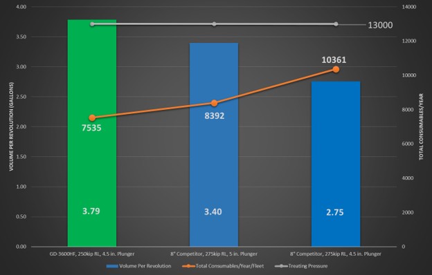
A calculator developed by GD Energy Products (GDEP) allows users to input information to quantify the benefit of using a longer-stroke pump in a specific application, Fig. 5.
DESIGNING FOR THE FUTURE
While stroke length is a primary differentiator in pump design, it is only one factor influencing overall performance. Gearbox configuration, structural design, serviceability, and load management all play important roles in determining how effectively a pump performs in the field.
Recognizing that modern frac fleets use a variety of power architectures, GDEP engineers designed the High Flow (HF) Series (Fig. 6) to support different horsepower requirements and power sources. Whether powered by dual-fuel, natural gas reciprocating engines or electric motors, the platform is designed to maintain consistent pumping performance across different driver technologies.
The proprietary pump design includes a removable gearbox for servicing and upgrades. The gearbox is configured for high power density, low vibration and optimal torque alignment, and it incorporates helical gearing for enhanced efficiency. The pump design also includes a bolt-on stuffing box for quick access to high-wear components and a reversible crosshead housing for extended operational life.
Most pumps on the market employ short stay rods that connect the frame nose plate to the fluid end flange. These legacy stay rods were designed for the intermittent duty cycles of years past. In today’s continuous pumping environments, they may perform adequately at 2,500 bhp, but as output increases to 3,000, 3,600, or 5,000 bhp, these rods are subjected to higher loads and increased cycle rates, leading to premature failure.
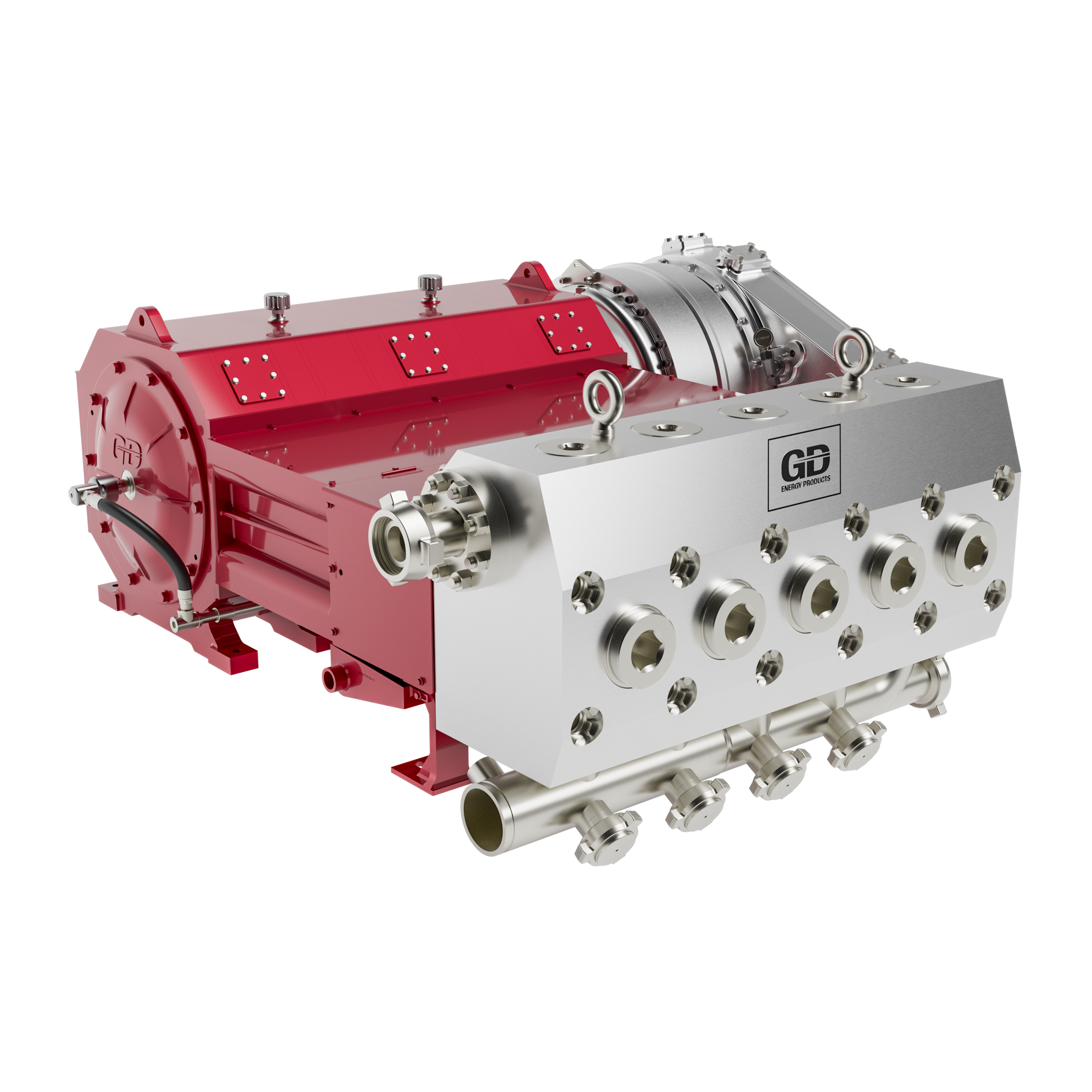
The HF Series addresses this with a through-stud tie rod design that more than triples the length of the tie rod, providing more material across which to distribute stresses and delivering longer overall tie rod service life. These tie rods are designed to match the life of the power end under continuous pumping conditions. In addition, the placement of rod fasteners behind and underneath the legacy fluid ends makes them difficult to reach. Because of the lower stress in the HF Series pump design, 40% fewer fasteners are required to affix the fluid end to the pump. The through-stud tie rod construction of the pump places these fasteners on front of the fluid end, which creates more clearance in the cradle area for safer, simpler access for maintenance.
The pump’s main bearings are designed in accordance with ISO standards and feature bearing geometry derived for continuous operation, at the full operating range of the pump. A proprietary coating applied to both thrust and journal bearings provides added protection during sub-optimal lubrication conditions, such as dry start-up and low-speed operation. This coating can improve the service life of these bearings by 50%.
The frame weldment was engineered to provide the structural integrity required for high-horsepower fracturing operations while ensuring manufacturing quality and repeatability. A proprietary weld joint design improves stress distribution throughout the frame, reducing fatigue accumulation and enhancing resistance to common weld-related failure modes.
To support today’s frac requirements, engineers prioritized modular architecture that allows key systems to be removed, replaced and serviced independently.
This modularity also enables standardization across the GD 3600HF and GD 5000HF platforms. Despite differing horsepower ratings, both pumps share the same heavy-duty frame and a large number of interchangeable components. This compatibility provides a clear advantage. The mounting and connection points are designed for straightforward integration, allowing either pump to be installed without rearranging trailers or reconfiguring plumbing or drive systems. This minimizes installation time, eliminates costly equipment modifications, accelerates deployment and simplifies parts inventory management.
PROVING THE PUMP
The pump underwent extensive factory and field testing to validate performance, durability and readiness for continuous-duty applications.
A full rod load endurance test was configured to run the pump at maximum rod load for 2 million cycles, to benchmark pump resilience and functionality. Design engineers used the critical strain data from this test to validate theoretical design calculations and ensure the design was ready for field deployment.
The pump was instrumented with 50 strain gauges, along with vibration, temperature and pressure sensors. Testing confirmed that the lubrication system and cooling systems performed as intended and that the pump met thermal performance requirements.
The lubrication system was further validated through combined testing on GDEP’s test stand and a 3,600-bhp pump trailer at a pump packager. During this testing, the pump operated across the full range of speeds and pressures, generating data that confirmed the lubrication system supports maximum pump performance across all operating conditions. Additionally, these data allow for optimal lube pump system and cooler specification by the end-user.
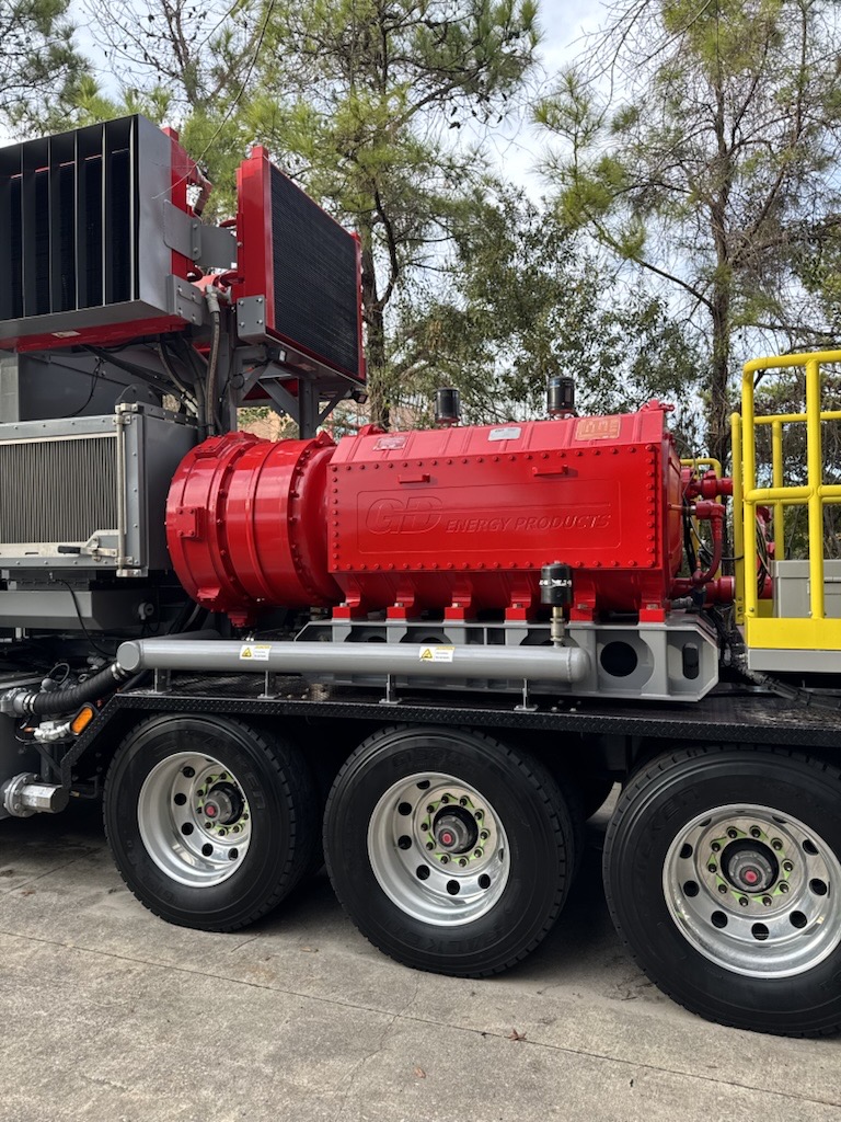
Horsepower capability was validated by operating the pump at full power and maximum rod load. Testing with a pump packager confirmed effective heat rejection and lubrication performance at peak horsepower.
The pump also underwent field testing with all major drivers, including dual-fuel and 100% natural gas engines, turbine direct drive and electric motors. Ongoing validation continues to monitor bearing performance, lubrication effectiveness and heat generation in real-world conditions.
Following testing, the pump was fully disassembled and subjected to nondestructive inspection of all load-bearing components. No fatigue-related damage or cracking was observed, and all wear rates remained within acceptable limits.
PUTTING THE PUMP TO WORK
The GD 3600HF high-flow frac pump was put to the test in the Montney shale in Alberta (Fig. 7), Canada—one of the largest unconventional gas plays in the world. The Montney is characterized by low-permeability siltstone and shale that requires high-pressure, high-volume fluid treatments to achieve commercial flowrates.
As operating conditions intensified, pressure-pumping demands increased. Higher rates and pressures, longer run times and greater sand tonnage per well placed significant strain on pumping equipment, resulting in more frequent maintenance and repeated repairs.
These maintenance demands limited operational uptime. The existing pumps were operating an average of 14 to 16 hrs per day and delivering approximately 1,500 hrs of fluid end life. The company providing hydraulic fracturing services needed a way to address changing conditions and was looking for a high-flow pump capable of delivering greater fluid throughput and improved reliability in continuous-duty applications. The wells in this drilling program required pumps operating between 10,000 and 12,500 psi that were also robust enough to handle average run times of approximately 19.5 hrs per day.
In April 2023, the company partnered with GDEP to deploy a fleet of 21 GD 3600HF frac pumps—a next-generation design born from a long-standing collaboration. The pumps were integrated into existing Tier 4 dual-fuel pumping units already on site.
Pump selection came down to performance. Designed with an 11-in. stroke, the GD 3600 HF delivers greater fluid displacement per revolution, allowing target flowrates to be maintained with fewer cycles at lower engine speeds. This reduces wear on critical components and extends maintenance intervals.
The lighter pump package, which weighs approximately 4,000 lbs. less than comparable pumps in its class, also simplified installation and logistics. Because the pumps were designed for compatibility with existing fleet configurations, deployment required no major equipment modifications.
To further support uptime, GDEP designs and manufactures the three primary consumable components that experience the most wear—including valves and seats, packing and plungers—in an ISO-certified facility. These components are stocked at strategically located service centers and supported through consignment programs that enable rapid delivery to the field, helping operators maintain continuity and minimize downtime.
Following deployment, GDEP worked closely with the service provider to monitor pump performance in live field conditions, using sensors and other monitoring equipment, to observe pump behavior and collect operational data. This feedback helped validate performance and identify opportunities for continued optimization, based on application requirements.
Operating at slower pump speeds to achieve the required flow rates significantly reduced the number of cycles experienced by critical components. Fewer cycles translated directly into less wear on valves, seats, packing and other consumables, reducing the frequency of fluid end maintenance and extending service intervals.
Consistent wear patterns observed across the fleet confirmed that the long-stroke, high-flow design distributes loads evenly and delivers predictable reliability improvements.
The company doubled fluid end life across the fleet, extending average service life to approximately 3,250 hrs, while increasing consumable life by 30%. By reducing maintenance interventions, these improvements helped improve safety and maximize uptime. In addition, the hydraulic fracturing fleet worked approximately 21 hrs per day for the first time. Together, these gains lowered total cost of ownership by 5% to 10%.
The service provider plans to evaluate expanding the use of the GD 3600HF across its fleet, as it continues to focus on improving uptime, reliability and overall operational efficiency.
CHANGING EXPECTATIONS
As alternative-powered frac fleets continue to evolve, improving engine efficiency alone is no longer enough. The ability to fully translate available horsepower into usable hydraulic horsepower at the well depends on how effectively the entire frac drive train works together.
Pump design plays a critical role in that equation. When the pump is properly matched to the driver, operators can achieve target flowrates while reducing unnecessary stress on critical components. This enables more of the available horsepower to be delivered to the well while lowering pump speeds, reducing maintenance demands and improving uptime.
As operators continue evaluating alternative power sources, system-level optimization will become increasingly important. The next phase of frac efficiency will be defined not only by cleaner power sources, but by how effectively that power is converted into performance at the wellsite.

ALEX FLORES, GD Energy Products V.P. of product management, is the lead for next-generation, high-horsepower pump technology development for global shale markets. With more than 20 years of experience in energy technology, he drives engineering-led innovation to increase completions efficiency, extend equipment life, reduce operational costs and support the transition to lower-emission power sources, including the rollout of high-efficiency pumping systems, natural-gas-powered solutions, and modular designs. He holds an MBA from Rice University and a bachelor’s degree from Texas A&M University.

CHRIS DEGGINGER is V.P. of engineering at GD Energy Products, where he defines product strategy and leads technical execution across fracturing, drilling and well service engineering organizations. Focused on delivering innovative pump solutions, Mr. Degginger has spent more than 25 years in sustaining engineering, field support and new product development. During his career, he has contributed to the design of GDEP’s industry-leading fluid ends, frac and drilling pumps and pump modules. He holds a bachelor’s degree. in mechanical engineering from Pittsburg State University.

TURNER HALL, P.E., is engineering director, power ends, at GD Energy Products, where he leads design, development and lifecycle management of high-horsepower frac pump power ends, overseeing product development, sustaining engineering and field performance initiatives. For more than a decade, he has been involved in frac pump design, testing and commissioning. Mr. Turner is a member of SPE and ASME and holds a bachelor’s degree in mechanical engineering from the University of Arkansas and a master’s degree in engineering and technology management from Oklahoma State University.
Related Articles- Multiphase surface pump boosts revenue for Pemex while reducing costs and environmental impact (June)
- Extended-length gas separation improves ESP stability in slug-prone Permian wells (June)
- Drilling technology: Optimizing high-pressure pump performance with fluid end advances (May)
- From post-mortem to real-time: A scalable approach to fracture diagnostics (May)
- Shaletech Report: Permian activity remains steady with growth through efficiencies (April)
- Before OPEC, there was Texas: A better path for Venezuela’s oil revival (February)
- Subsea technology- Corrosion monitoring: From failure to success (February 2024)
- Applying ultra-deep LWD resistivity technology successfully in a SAGD operation (May 2019)
- Adoption of wireless intelligent completions advances (May 2019)
- Majors double down as takeaway crunch eases (April 2019)
- What’s new in well logging and formation evaluation (April 2019)
- Qualification of a 20,000-psi subsea BOP: A collaborative approach (February 2019)