What's new in artificial lift?
Continuing last month’s “What’s new in artificial lift?” discussion, this report covers recent developments in the areas of electric submersible pumps (ESPs), plunger lift and gas lift developments.
ESP DEVELOPMENTS
An ESP downhole assembly will, typically, include the ESP; a gas handler/separator or standard intake; a seal section; a submersible motor with a connected power cable that runs to the surface; and often a downhole sensor package that communicates pump and wellbore performance information back to a surface interface system. The surface equipment may include a variable speed drive (VSD) or switchboard, a motor protection system and/or an intelligent control system designed for applications that require advanced system control and monitoring.
Managing production decline. Production from unconventional reservoirs often drops from initial rates of 3,000 bopd or more, to less than 50 bopd in just a year or two. Traditionally, producers have installed an ESP system, when production was high, then replaced it with a rod-lift pump when the production rate declined, because ESP systems could not handle the wide and varying flow range.
The Baker Hughes FLEXPumpER extended-range pump eliminates the need for system change-outs. Designed for wells with quickly changing flowrates, high gas/oil ratios (GOR) and high solids content, its flow range of 50 bopd to 2,900 bopd—the industry’s widest operating range for a single pump—provides operational flexibility for the duration of an unconventional well’s production cycle, and maximizes production while extending ESP system run life.
The extended-range pump addresses gas locking and gas slugs that commonly result from influxes of free, compressible gas in the production stream. Both conditions increase downtime and can lead to equipment failure.
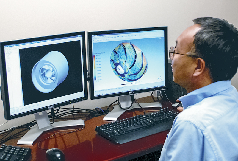
The advanced design of the FLEXPumpER pump (Fig. 1) extends its operational flexibility to reduce operating costs, improve reliability and optimize production in changing downhole conditions. Patent-pending advanced turbulence mitigation (ATM) technology increases pumping efficiency and reduces gas locking. A re-designed bearing system allows the pump to withstand short-term elevated temperatures generated by gas slugs. Particle swirl suppression ribs in the diffuser provide abrasion resistance and reduce abrasion buildup.
Using a Baker Hughes CENesis ESP system with FLEXPumpER extended range pumping technology, an operator in East Texas increased output 20% by managing gas entrained in the production stream. The operator’s well had been producing an average 860 bopd while experiencing frequent ESP system shutdowns—sometimes multiple times a day—as a result of gas slugs and elevated bottomhole temperatures. Gas/oil ratios and water cut varied daily, which led to down-thrust issues and poor reliability rates.
After analyzing the well conditions, the service company installed a CENesis ESP system with FLEXPumpER technology. The ESP system maintained reliable operations and provided superior down-thrust handling capabilities, even when production dropped as low as 800 bopd with 50% water cut. Gas averaged 650 Mcf with some significant slugging, but the ESP system maintained steady drawdown while running at 46 Hz.
Production after the ESP/FLEXPumpER solution averaged 1,034 bopd—a 20% increase over the previous rate. Two additional systems were installed within six weeks, with similar results.
In an unconventional Oklahoma well, an ESP with FLEXPumpER technology enabled an operator to maintain production with flowrates as low as 13 bopd and pump intake pressure less than 100 psi, without an artificial lift change-out. In a well with high levels of sand and other abrasives, previous ESP failures had been attributed to sand and debris plugging flow passages of radial pump stages. The Baker Hughes solution improved reliability and maintained production at flowrates from 13 bopd to 344 bopd, with 78.5% water cut.
Taming the curve. Wellbore geometry can impact unconventional well production significantly. The industry standard buildup or deviation rate is 6°/100 ft for an ESP system to reliably pass through the curved section of a horizontal or deviated wellbore. Increasingly, operators require a tighter radius to open the maximum amount of reservoir to the wellbore.
Baker Hughes has addressed this requirement with the CENesis Curve tight-radius ESP system, which can reliably pass through buildup rates of up to 25°/100 ft, with no damage to the system. The tight-radius system can be set deeper in the lateral section of a well, closer to the producing zones. The lower setting depth provides a larger fluid column above the pump and permits greater pressure drawdown for higher production rates and increased overall reserve recovery. Another advantage of deeper setting depths is higher pump intake pressures, which improve ESP system reliability by limiting gas accumulation in the pump and preventing shutdowns, due to gas locking.
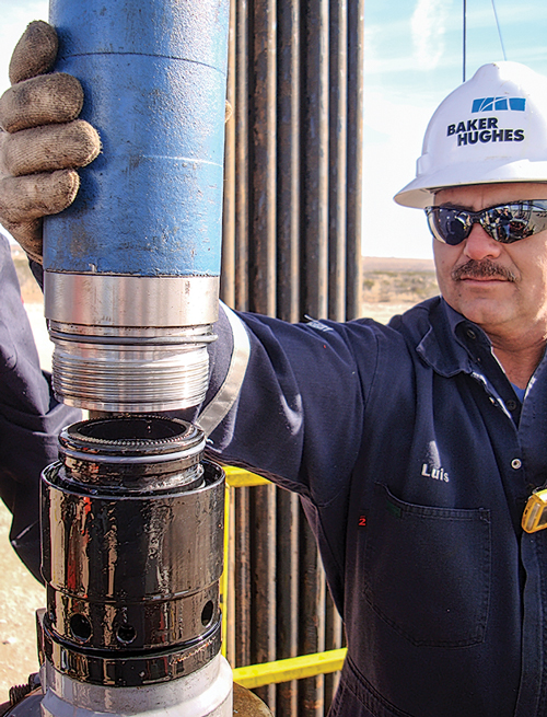
The key to flexibility and reliability of the new system is a patented, boltless method of connecting system components, Fig. 2. Traditionally, ESP system components are connected by a flange that uses bolts to secure the sections. In tight-radius wellbores, the bolted flanges are subjected to extra stress, resulting in potential equipment damage. The CENesis Curve system eliminates the bolts and strengthens the connection to withstand a greater bend radius. The boltless connection method reduces the risk of dropping bolts or tools downhole, and the subsequent downtime and cost associated with a fishing operation. It also cuts installation time by more than 50%.
Tensile strength of the tight-radius ESP system nearly doubles that of a standard ESP system. If a workover is required during the life of the ESP, reliability during pulls is improved significantly. Baker Hughes is the only service company offering this patented, tight-radius ESP technology.
The CENesis Curve system is building an impressive track record. In a December 2014 installation in the Permian basin, the system passed through a 12.5°/100-ft deviation, was set 445 ft deeper in the well than previous ESP systems, and improved oil production 80% in a well that had previously seen three ESP failures. The ESP solution for this well also included a FLEXPumpER extended-rate pump, which eliminated the need for a costly planned workover and artificial lift change-out as production rates decline.
In Oklahoma, a well mistakenly drilled with a 21°/100-ft dogleg severity at 5,945 ft, true vertical depth (TVD), left an operator faced with a difficult choice: switch to a less effective method of artificial left, since the ESP system originally planned for the well was unable to handle extreme buildup rates, or incur the cost of re-drilling the well. The CENesis Curve system offered a third option. The ESP was installed successfully and passed through the 21°/100-ft deviation, allowing the operator to meet the daily production target of 400 bopd without incurring additional drilling costs. According to the manufacturer, the system is still functioning.
New extended-life ESP. Gassy, abrasive and high-temperature formations, combined with steep flow declines, changes in flowrates, varying stresses and solids production, often force ESPs to operate outside optimum ranges or pump specifications. This results in mechanical failures and the need for costly pump replacements that drive up operational downtime and cost.
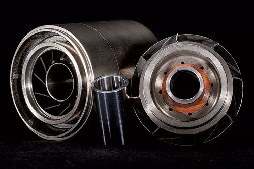
Schlumberger’s new REDA Continuum unconventional extended-life ESP, with a mixed-flow stage pump (Fig. 3) developed for the unpredictable and changing flow of shale wells, provides greater efficiency and durability in a wider operating range than conventional pumps. This enhances recovery and reliability, and extends well life. Depending on the current flowrate of a given well, the system can optimize production or decrease production to extend the run life of the ESP. The expanded operating range improves pump performance at low rates, in transient flow and in abrasive environments. After extensive field testing, the system is delivering reliable, extended well life results in the Rocky Mountain region of the U.S.
The system provides continuous operation over wide flow ranges to match well production flows, even when flows are outside the pump-designed operating range. The Continuum pump is factory-shimmed, enabling faster, more reliable connections in the field. It is deployed with the REDA Maximus, a factory-prefilled motor that minimizes assembly time at the wellbore.
By maximizing run time and run life to regulate production, the pump reduces the need for expensive rig intervention to change out the ESP. The re-engineered system decreases stage erosion to handle abrasive conditions, with wider vanes to accommodate higher gas volumes. Engineered with computational fluid dynamics to model stage geometry and architecture, the system provides higher lift with less power consumption.
Key design components include a more robust compression capability that enables the ESP to operate at flowrates below the lower limits of conventional pump operating ranges. The minimum flowrate operating range is determined by a protector thrust bearing, motor cooling and a shaft brake horsepower limit. A downhole gauge provides measurements for continued monitoring and control, along with the capability to adjust to changing well conditions
and flowrates.
The system also includes a field-proven, multiphase gas-handling system designed to avoid gas lock for handling more than 90% gas volume fraction at the intake, and up to 75% through the pump. Built-in real-time surveillance enables remote communication and simultaneous control of multiple wells across several fields.
The extended-life ESP system was developed for a phased rollout of three pump capacities, depending on well flowrates. Each pump has a different flow envelope. The Continuum 1000, introduced in November 2014, handles low flowrates from 200 bopd to 1,350 bopd. The Continuum 4000, designed for high flowrates and abrasive stage wear, was introduced in March 2015; and the 2500, for mid-flowrates, was launched in May.
To ensure optimum efficiency, the pumps can be switched out as flowrates change. For example, the Continuum 2500 can be swtiched easily to the 1000 model, to accommodate reduced flow. Like conventional ESP systems, the pump is conveyed on tubing. When switching pumps is necessary, the completion tubing is pulled, to enable installation of the new pump using a conventional workover rig.
During field trials, a Rocky Mountain operator installed a REDA Continuum 4000 on a well where anticipated natural flow was 4,000 bopd. The pump increased production to 5,500 bopd. Although production has declined to below 3,000 bopd, the Continuum 4000 is still operating eight months after it was installed in September 2014.
GE offers new submersible motors. GE Oil & Gas recently introduced the new Dura Plus motor line that offers highly efficient submersible motors in 4-in. and 5.62-in. diameters, to meet the demanding requirements in oil production applications. Dura Plus motors utilize improved electrical design to provide higher efficiency and power density. Higher copper content in the rotors and stators is complemented by upgraded bearings for rotor stability, which provide smoother operation and longer run life.
The 4.56-in. models range from 19 hp to 375 hp in single motors, and specific models can be installed in tandem to provide up to 500 hp. The 5.62-in. motors range from 38 hp to 675 hp in single motors, and with specified equipment are compatible with tandem installation to provide up to 950 hp. These new models feature plug-in motor lead cables for faster installation at the well site.
Use of a downhole sensor can also contribute to longer run life, and these new motors offer standard sensor thermocouple and base to adapt to GE Zenith sensors. The motor housing is available in carbon steel, with T9 Chrome housing/400 stainless steel head and base as an option.
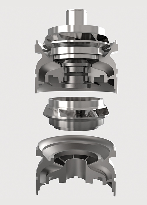
Abrasion-resistant pumps. To complement the new motors, GE’s Lift Plus pump line has been extended to include a new series of wide-ranging abrasion-resistant pumps. These new Lift Plus Q+ pumps are a solution designed to extend ESP run time in abrasive wells that require a wide operating range, due to fast decline rates of the well inflow performance ratio. The patented Lift Plus Q+ pump design (Fig. 4) is the first in the industry to provide a tungsten carbide bearing for upthrust protection, thereby expanding the pump’s operating range by as much as 300%. Combined with the radial support and downthrust protection provided by the existing AR modular design, Lift Plus Q+ pumps allow the producer to use one pump, as well conditions change to lower flowrates, reducing workovers, due to rapid decline rates.
The initial release of Lift Plus Q+ pumps includes a 4-in. diameter with BEP at 1,000 bopd, or 1,750 bopd at 60 Hz. The operating range for the 1,000-bopd model is from 300 bopd to 1,750 bopd, and the operating range for the 1750 model is from 500 bopd to 2,730 bopd at 60 Hz.
Reaching new summits. Summit ESP, an electric submersible pump systems provider, announced it completed its 4,000th installation during first-quarter 2015. Celebrating only four years in business, this achievement reflects the quick adoption of Summit’s products and services by the industry, and the reliability of their Corsair motors and Tiger Shark pumps.
This Permian basin installation is the culmination of rapid growth, from just a few employees working at a single location four years ago, to nearly 500 employees and 23 service-and-sales locations today. According to the company, Summit ESP is now the second-largest supplier in the U.S. for downhole ESPs. John Kenner, Summit president and CEO, said “Summit is an independent ESP company, managed and staffed by experienced ESP people who are focused fully and solely on ESPs. Our employees average over 11 years of ESP work experience.”
PLUNGER LIFT DEVELOPMENTS
In plunger lift systems, the detection of the plunger is one of the most critical, yet least advanced, aspects of the system. Missed arrivals and false plunger detections lead to poor system performance and undesired events, such as well shutdowns. Even worse, catastrophic events, such as the breach of a lubricator, can occur, causing damage to equipment, and operator injury or death.
Magnetic sensing in plunger lift. Until recently, it simply has been accepted that the only way to detect a plunger is by using current induced in a coil, as the plunger passes by the sensor. This current is used to close a relay or switch. Open/closed status is communicated to a nearby control system, which then actuates one or more pneumatic valves to control flow of gas and fluids. Plunger detection also is used frequently in various optimization methods. The problems with coil-based technology are numerous. To initiate enough current, the plunger must be made of ferrous materials and must travel by the sensor at a minimum speed. If these conditions are not met, the plunger arrival can be missed easily.
False detections are also frequent with coil-based technology. With no way to determine differences between plungers and outside influences, such as a nearby compressor, sensors can falsely detect an arrival, throwing off optimization routines. Coil-based sensors present a number of additional challenges, such as variations in coil manufacturing, shorter product life and high power consumption.
New sensor architecture by Extreme Telematics Corp. utilizes a magnetic integrated circuit to detect the magnetic field, and then translates it into a digital domain. This solution not only reduces power consumption but also allows more detailed processing to occur. A range of digital filters and algorithms can be applied easily to ensure that operators are accurately interpreting the magnetic field, as opposed to simply relying on a spike in current coming off a coil. Not only are the issues surrounding slow-moving plungers eliminated, the ability to adjust sensitivity is added. This allows for more accurate detection of a wider range of plunger materials and types at virtually any velocity.
The lower sensitivity settings are used with ferrous plungers that generate a large-magnitude change. This allows the sensor to ignore small fluctuations and eliminate the problems associated with false detections from vibrations, and electrical interference from surrounding equipment. Conversely, sensitivity can be increased when dealing with smaller or non-ferrous plungers that generate a smaller-magnitude signal, which eliminates missed arrivals.
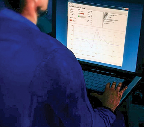
This fundamental shift in the design of plunger arrival sensors also allows a number of other benefits. These include, but are not limited to, less dependence on operational voltage, a wider range of interfaces, lower power consumption, and more visibility of the signal in the magnetic domain. This increased visibility allows for streaming and logging of real-time data that show exactly the behavior of the signal, as a plunger enters the field of view, Fig. 5. This allows for greater understanding of what a plunger looks like in the magnetic domain, how to interpret what is and is not a plunger, and how to adjust the settings to give plunger lift operators and technicians the reliable detection that they seek.
The establishment of this platform enables development of enhancements that were not previously possible. The next wave of this innovation includes interpreting these waveforms to derive an accurate velocity of the plunger at surface. This not only provides the operator critical safety information, it allows prevention of costly, dangerous events that are commonplace in plunger lift. It also provides more accurate information for corrective measures and enhanced optimization algorithms.
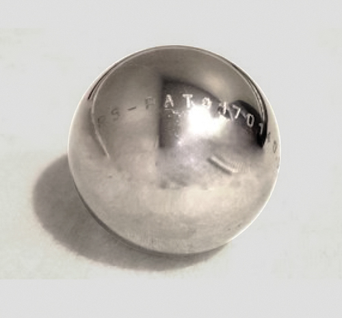
Sphere plunger. IPS, a Superior Energy Services company, has developed what is reported to be the lowest-friction plunger on the market, the Sphere. It is the most recent addition to the IPS line of conventional plungers. The circular design (Fig. 6) allows this plunger to reach deeper into deviations and capture fluid that was previously unreachable by conventional plunger designs. It is the first plunger to reach the coveted 90º mark, according to the company. The Sphere is well-suited for doglegged wells that often wear conventional plungers flat on one side. With a low-friction design and high rotation effect, production on marginal wells can be increased significantly. The design also allows maximum fall rates that have been tracked at 500+ ft/min.
GAS LIFT DEVELOPMENTS
Gas lift involves injecting gas through a well’s tubing-casing annulus. Injected gas aerates the fluid to reduce its density; the formation pressure is then able to lift the fluid column and force it up the wellbore. Depending on the well’s producing characteristics, and the specific characteristics of the gas-lift equipment, gas may be injected continuously
or intermittently.
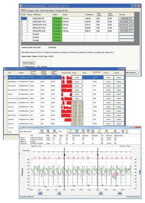
Advanced automation for gas lift operations. The PCS Ferguson Gas Lift Manager (GLM) from Dover Artificial Lift automatically stabilizes injection of gas lift wells, ensuring optimal well performance and reducing the need for intervention at the well site. The GLM provides several main, innovative features for gas lift operations, along with an array of system reports, Fig. 7.
Stable gas injection. Stabilized injection rates are critical to efficient gas lift operations. A proportional integral derivative (PID) loop is a well flow or production control mechanism that provides feedback on the well production. It is an effective method of helping stabilize well flow. However, application expertise and measurement device knowledge are key to optimized control. The GLM design employs a unique method of separating the response time and system dynamics into separate user-programmable settings. This allows the customer to quickly, and easily, retune injection operations when the dynamics of the system change, without recalculation of PID mathematical parameters.
Automatic kickoff. Applying high-pressure and high-volume gas too rapidly can damage the downhole injection valves and destroy the effectiveness of new installations. The GLM provides patent-pending, API-compliant, selectable or automatic kick-off, ramp and re-start algorithms that are designed to greatly reduce or eliminate the risk of damage to downhole gas injection valves.
Measurement device data smoothing. The precise nature of gas measurement often can create data anomalies that can impact PID control. The GLM offers “data smoothing” options at injection inputs to help stabilize injection, minimize overshoot and keep PID adjustments to a minimum, to increase the life of surface injection valve components.
Well design data capture. The GLM stores well design and installation information (such as wellbore type, mandrel types, number of valves and their type, closing pressures, installation depths, and pressure design settings) for each well. This information can help troubleshoot problems while answering critical questions quickly.
Flexible solutions for pad layouts. Employing a local wireless network, the controller can be located anywhere on the well pad. Additional gas lift remote devices can be added to the network, to manage “dislocated” injection points. Remote I/O is available for wellhead monitoring and control, offering the flexibility to accommodate any pad layout.
AUTOMATION AND CONTROL
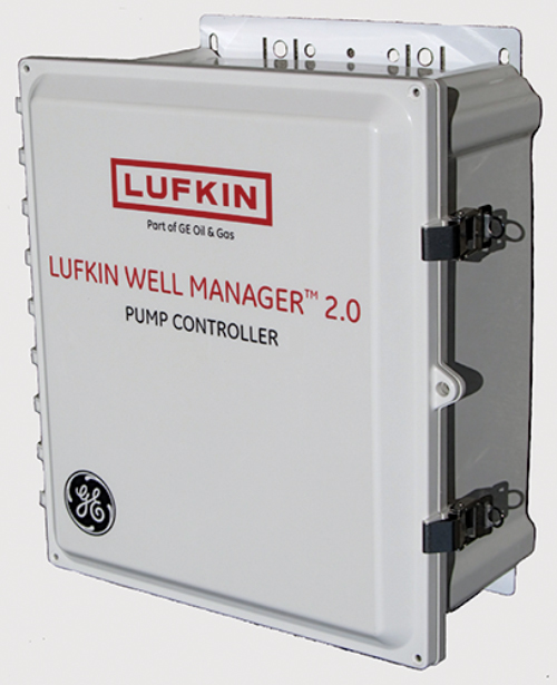
Building on Lufkin Automation’s industry-leading rod pump controller platform, GE Oil & Gas has released the next-generation artificial lift controller, the Lufkin Well Manager 2.0 (LWM 2.0), Fig. 8. More than a rod pump controller, the LWM 2.0 features advanced pump-off and VSD functions, and downhole calculations considered by some to be the most accurate in the industry. It can support wells on various artificial lift types. It leverages advanced control technology from GE, to provide the operator a single hardware platform, from wellhead to pipeline, for automation, control, monitoring and optimization functionality throughout a well’s life cycle.
The new controller utilizes advanced data process capabilities and control logic for real-time production optimization and future failure prediction. Optimized production and fewer lift system failures result in increased production and decreased lifting costs.
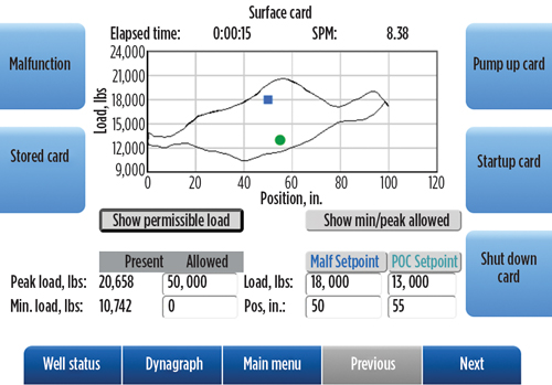
The device includes a full-color, high-resolution user interface (Fig. 9), complete with onboard Wi-Fi connectivity. A field operator simply needs to drive up to the well and connect with a personal computer, tablet or smart phone to retrieve the data he needs. Because LWM 2.0 acts as a web server, there is no need for proprietary software on these devices.
It also functions as a standard PLC, supporting ladder logic and PID control functions with multiple options for I/O expansion, including AI, AO, DIO, PI, RTD and thermocouple inputs. Its modular design provides easy field service solutions and includes a communications module, complete with multiple Ethernet ports, RS-232, RS-485 and Wi-Fi communications.
In a SCADA environment, Modbus RTU and TCP are supported in both master and slave modes. Connectivity via Ethernet is fully supported, as are optional communication protocols, such as HART, Profibus, CANopen and Foundation Fieldbus. Dynamic Modbus Register Configuration functionality provides the operator with the flexibility to design the most efficient SCADA system.
LWM 2.0 is also available as part of GE’s Field Vantage solution that applies the power of the industrial internet to help operators visualize well, field and operation-wide data for smart deployment of resources and decision-making. It also helps predict issues with lift systems, can aid in optimizing production, and reduces operating costs.
OTHER DEVELOPMENTS
At some point, production from almost every well will depend on artificial lift. Each well is a new challenge that defies a single-solution approach. Yet too often, artificial lift systems are presented as one-type-fits-all. While field experience helps to narrow the lift type selection for a well, continual life-of-well production optimization remains a challenge.
Thinking beyond lift type and tools. Leveraging the company’s artificial lift depth, breath and experience, Weatherford’s production optimization consulting group provides operators unbiased recommendations for maximizing asset value at the well, reservoir and field levels. Using a formal project management methodology, consultants evaluate the potential of all types of artificial lift and suggest the design that best fits each well. The result is a customized, life-of-well lift plan that helps operators produce more oil and gas for less expense while lengthening the life of the asset.
The consulting team uses the Weatherford AIM, Gain, Sustain methodology. The asset inspection methodology (AIM) phase includes preliminary analysis of current practices in managing the wells/assets and identification of the infrastructure requirements for real-time optimization. During the Gain phase, consultants perform the detailed analysis and prioritize the optimization opportunities. They make recommendations to increase uptime, improve asset performance and deliver early investment returns. Production increases resulting from the AIM and Gain phases are sustained in this third phase, in which teams implement new production optimization technologies, fine-tune processes, and train field workers to sustain profitability over the life of the asset.
Using this comprehensive analysis method, along with proprietary optimization technologies, such as the company’s LOWIS life-of-well monitoring software, the team makes remediation recommendations across all types of wells. The recommended changes range from setting points and altering the rod pump stroke length to the change in the injection gas rate or frequency. These alterations help reduce the rate of decline, and thus produce more oil by increasing the meantime between failures, and ultimately reducing operating expenditures. ![]()
- What's new in production (February 2024)
- U.S. operators reduce activity as crude prices plunge (February 2024)
- U.S. producing gas wells increase despite low prices (February 2024)
- U.S. oil and natural gas production hits record highs (February 2024)
- Dallas Fed: E&P activity essentially unchanged; optimism wanes as uncertainty jumps (January 2024)
- Enhancing preparedness: The critical role of well control system surveys (December 2023)
- Applying ultra-deep LWD resistivity technology successfully in a SAGD operation (May 2019)
- Adoption of wireless intelligent completions advances (May 2019)
- Majors double down as takeaway crunch eases (April 2019)
- What’s new in well logging and formation evaluation (April 2019)
- Qualification of a 20,000-psi subsea BOP: A collaborative approach (February 2019)
- ConocoPhillips’ Greg Leveille sees rapid trajectory of technical advancement continuing (February 2019)

