Innovative PDC bit brings digital intelligence-driven design to Middle Eastern application
Re-entering wells often involves drilling long lateral sections across reservoirs of varied density, typically with a rotary steerable system. Drilling across these reservoirs can present unique challenges that put limits on the optimal potential performance of the section. Traditionally, an analysis of surface parameter data in conjunction with a standard drill bit dull analysis can identify and address such operating limits.
This approach can be effective but has limitations as well. It can be a challenge to properly identify and document the downhole severity of the operating limiting issue, along with the correlation and effects of this limitation to that of the drill bit design. This can lead to uncertainties in quantifying the overall effectiveness of a chosen design modification to address the operating limit.
The Halliburton team used the latest digital intelligence technologies within the existing Design at the Customer Interface (DatCI) process to successfully identify the type of downhole dysfunction limiting performance and its severity. The approach enabled precise decision-making on the drill bit design modifications and captured downhole feedback on the design changes to limit downhole dysfunction, which further increased overall section performance. This improved process is at the core of the Hedron line of drill bits, which integrates downhole Cerebro data intelligence, in conjunction with an automated dull grading system (Oculus), to achieve record-breaking field performance.
DESIGN PROCESS
The traditional process to optimize performance relies on an analysis of the basic surface parameters applied, responding torque and rate of penetration (ROP) signature, along with the condition of the retrieved bit dull. With this information, a team makes alterations, either through step changes in applied parameters or a modification to the drill bit design to further improve maximum achievable ROP performance of the section. This approach is limited by a lack of understanding of downhole dysfunctions that hinders continuous section improvement. Because surface parameters are not always an accurate depiction of what’s occurring closer to the formation being drilled, Halliburton introduced Cerebro downhole in-bit sensor equipment to better understand and accurately document motions of the drill bit from well to well, with modifications to surface parameters, formations, and drill bit design.
The first step of the process identified any limitations potentially correlated to the drill bit design. Halliburton worked with the directional company to optimize parameters, to reach the maximum potential of the existing design. During the development process, the team combined information from multiple sources to make an accurate present-day performance case. This includes surface drilling parameters, downhole vibrations data (from the RSS), at-bit vibrations data and post-run intelligent drill bit dull grading. Halliburton used this information to determine the maximum performance that the current design and bottomhole assembly (BHA) could achieve without inducing an undesirable downhole dysfunction.
Once the team established the base case for the current bit and BHA combination and dysfunction signatures, they modified the existing design to reduce occurrence of bit-induced dysfunctions to push the performance beyond the recognized maximum. In the past, design modifications only produced incremental performance improvements, partially due to uncertainties of the true section drilling mechanisms, which limited performance. However, the holistic nature of the available downhole at-bit data made a more substantial design change possible. The team then conducted a wide-ranging study of the various vibration mechanisms, including at-bit stick slip, torsional, lateral and axial. Each bit dull passed through an automated dull grading system to digitally document and identify dull trends in comparison to the dysfunctions seen downhole. The team used a combination of these results as a guide to design a modified bit specifically for the subject application.
The at-bit sensor helped identify problematic areas and the type of vibrations being experienced while drilling the section. In addition to this, the team quantified the magnitude of the vibrations. With the vibrations now clearly mapped, they accurately integrated vibration mitigation mechanisms into the design philosophy. Artificial intelligence-based, automated bit dull grading helped to quickly classify the exact type of cutter damage observed at different profile areas of the existing design. By linking this dull grading profile with the bit design, the team identified potential design improvements to increase efficiency without exacting extra damage to the cutting structure, which improved the location and orientation of the cutters. Finally, they identified where to place the latest Geometrix-shaped cutters, along with premium, high-impact cutters to minimize damage risk and maximize drilling efficiency.
This improved bit design delivered lower vibrations, due to enhanced drilling efficiency. Because of the increase in bit stability, additional benefits from the RSS in the form of reduced dysfunctions showed further improvement in the overall rate of penetration. The new design improved the drilling efficiency and proved the prowess of the applied holistic model. This simple-but-powerful approach can be modified and applied to improve bit design, to fit any type of application requirement. The subsequent sections will delve deeper into how each technology was used to aid the digitally enhanced design process, Table 1.

Table. 1. Identification of downhole drilling problems, subsequent solution, and value delivered.
At-bit vibration analysis. Effective drill bit performance analysis requires crucial information. Accurate high-frequency measurements over the course of the entire run provide a very powerful starting point to a clear picture of what occurs downhole. The Cerebro electronic data capture system gives a high-frequency look at data from the bit. The technology gives reliable, high-data-rate measurements of inclination, vibration, rotation, and the earth’s magnetic field movement around the bit.
By understanding motion, the team can map the source and type of drilling dysfunction. Once they identify the drilling dysfunction, they can map against operating conditions and parameters or formation. This map provides a guide to optimizing drilling parameters in each application. Drilling dysfunction identification may also be used in certain cases to optimize bit design, to mitigate dysfunction and improve overall drilling performance.
For the current bit design approach, the team used the Cerebro system to get a sense of actual, downhole at-bit vibrations. The classification of vibrations required them to pinpoint the exact type of vibrations to apply design modifications, which assists in reducing that specific type of vibrations. The team used multiple, repeatable runs with Cerebro to plot vibrations, to visualize the highest and most problematic dysfunction types.
Due to the nature of the section, lateral vibrations were the biggest point of concern. The team collected the actual magnitude of lateral vibrations from several runs and compared them, using different parameters. The team verified the hypothesis of lateral vibrations, illustrating lateral vibration severity with different parameter combinations, Fig. 1.
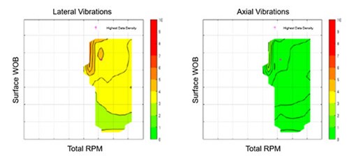
Fig. 1. Measuring vibration severity at different WOB/RPM parameters.
In addition to looking at runs separately, the team plotted multiple runs to understand vibrations at different depths with changing parameters, Fig. 2. The team looked simultaneously at multiple runs, which helped them understand the nuances in different areas of the field and to better understand how variations in depths and locations correlated to changes in drilling mechanics and vibrations. Following is an example of such plotted data, which show vibrations for three different runs that use the same bit and BHA.
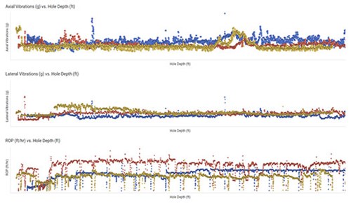
Fig. 2. Multiple offset ROP and vibration output comparison.
The ability to gather and study minute details like this helped to gain insight into the application that was not previously possible. Similarly, incorporating these insights provides a paradigm shift that changes drill bit design. Now, companies can understand the dysfunction downhole and assess the effects of this on the durability and performance of the drill bit’s cutting structure.
Automated dull grading. Conventionally, bits are dull-graded, based on visual inspection: examiners identify different cutter damage patterns, based on theory and personal experience. In addition, the only way to combine dull analysis of a large number of bits is to identify damage patterns by entering the cutter data across all blades. The possibility to merge big sets of data becomes tedious because of this labor-intensive examination technique. The new Halliburton Hedron platform of fixed cutter PDC drill bits uses Oculus advanced dull analytics. The Oculus system is a state-of-the-art automated dull grading system that utilizes machine-learning algorithms to capture precise dull information for each individual cutter of drill bits.
Accurate dull bit forensics have always been a key tenant to delivering superior drill bit performance. The Oculus system transforms this critical process from one that is largely subjective into something that is data-driven. It increases the potential number of data points analyzed from single digits to potentially thousands of relevant offsets. The Oculus system efficiently captures the dull data for every cutter, and it also provides modern analysis and visualization tools. The drill bit system can use big data analytics techniques and cloud infrastructure to seamlessly correlate all relevant data streams and integrate them into the bit design process. To implement the Oculus system in the current application, a dedicated field analysis of reference bit design showed a consistent dull pattern across the design profile of the bit, Fig. 3.
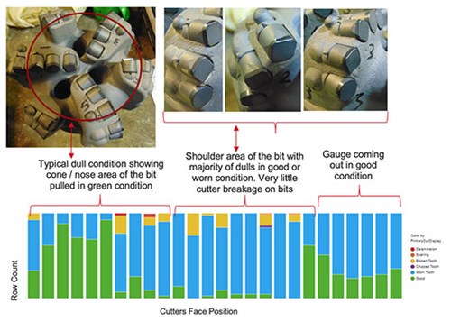
Fig. 3. Dull grading system.
Excluding the occasional aggressive dull condition, most of the cutter dull pattern signified smooth bit condition with minimal damage. A majority of the bit runs in this application operated at maximum drilling parameters, in terms of WOB and rotary RPM. Interval lithology is comprised of homogenous layers with some slight interbedding. This formation’s characteristics were supported by the bit dull condition, as there was no abnormal over-engagement of cutters across the primary cutting structure. This lowered the risk of cutter overload that can lead to premature chippage or breakage.
Initially, to improve performance, the team tested a PDC bit with axially point- loaded shaped cutters in the shoulder area of the bit in this application. Subsequently, they established it as a main drill bit for this section; however, they took BHA and other performance improvement steps for efficiency improvements. Results from these changes were capped at a certain level, which led to the need for a more aggressive design. When the team decreased the diamond volume, it negatively affected the bit’s performance in terms of stability and also exacerbated the minor breakage seen in the shoulder during formation transitions. Therefore, the team required a different solution with the existing design profile of the bit.
Bit design change. The team used the subject bit on a rotary steerable drive BHA, so the aggressiveness, stability and directional response of the bit had to be considered before making design changes. Based on the Oculus analysis, the team decided to increase cutter efficiency while keeping the same profile and cutter positions. The reference bit was limited by weight on bit (WOB) controlling parameters inside the reservoir, due to excessive vibrations in the lateral section.
The team introduced optimum back rake scheme as a first iteration step to increase efficiency with low susceptibility to impact damage. Three basic areas in the design profile—the cone, nose, and shoulder—were examined for changes in back rake regime, Fig. 4. No changes were made in the cone area of the bit, as cone cutters normally see high engagement forces. Over-engagement of cone cutters could adversely affect bit stability, which leads to aggravated vibration levels. However, in the nose and shoulder areas of the bit, the team arranged a calculated change in back rakes for efficiency improvement.
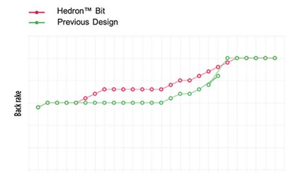
Fig. 4. Back rake scheme analysis.
The team conducted theoretical comparison of reference and updated the new design’s torque and efficiency model while keeping the remaining parameters constant for both bits. Proprietary modeling software calculated a theoretical increase of bit efficiency by approximately 26%, compared to reference design at various WOB inputs, Fig. 5.
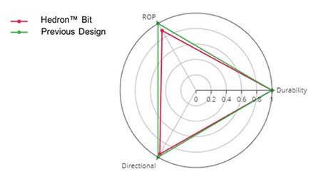
Fig. 5. Efficiency improvement modeling.
RESULTS
The team tested the new Hedron design in the 2022 drilling campaign and set a field record after the first run. In the first lateral well, the bit demonstrated its potential by exceeding all other 2022 offset well ROPs, Fig. 6.
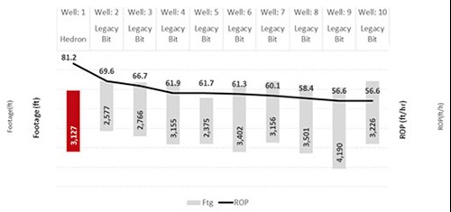
Fig. 6. Hedron design ROP performance in lateral section.
It delivered 17% more overall ROP while drilling with same parameters constraint of limited WOB. It recorded lower vibrations throughout the interval, which the following Cerebro vibration data analysis verifies in Fig. 7. Bit dull was graded 1-1-WT-X-I-NO-TD.

Fig. 7. Cerebro vibration data—single well overview.
After the success of the 6 1/8-in. bit in the lateral section, the team executed a swift study to implement the new design in the curve section, drilling through interbedded layers of carbonates. Oculus analysis confirmed the smooth dull pattern with no abnormal chippage or breakage on the parent 05 blade round cutter design. The challenge of drilling a curved section with a bent motor requires smooth directional control to achieve required build rates. Based on the historical field experience, existing 05 blade design profile gives smooth directional control results. As a first step of optimization, the new shaped cutters were introduced on the same parent design to maximize ROP efficiency, Fig. 8.
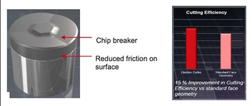
Fig. 8. Gladius cutter technology.
These latest cutters work on the chip breaker concept to reduce friction on face by sharp edge at higher engagement and improved chip flow to help deflect cutting efficiency. The team selected a targeted profile location to deploy the new cutters, to maximize cutter productivity and minimize risk of any damage that can hamper durability. The team tested the new Hedron design in the same, ongoing, 2022 drilling campaign. The five-bladed bit incorporated with Gladius cutters outperformed the field ROPs and achieved a 114% efficiency improvement, Fig. 9.
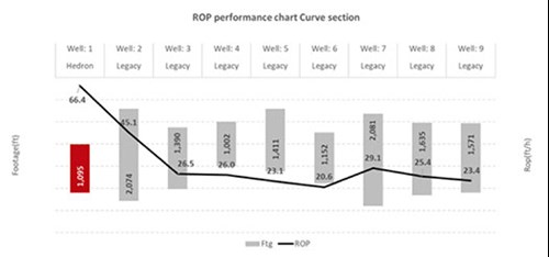
Fig. 9. ROP performance chart in the curve section.
The bit shows excellent stability, along with durability and dull came as 1-1-WT-X-I-NO-TD, Fig. 10.

Fig. 10. Bit was pulled in good dull condition.
The Hedron bit improves drilling efficiency and keeps the parameters within operating limits. This success covered the full solution development: the team identified the challenge; verified it with an advanced automated analytical approach; and developed a technical solution. Based on the success of the first lateral run, the operator elected to use the technology for most common lateral drilling sections, targeting efficiency improvement across the entire project. The Hedron bit emerged with promising dull grading, as there was no uncharacteristic damage seen on the bit profile.
- Rugged, explosion-proof computers safeguard offshore rigs (January)
- Drilling advances: Bottlenecks? What bottlenecks? (January)
- The evolution of remote-controlled FPSOs (January)
- How AI-driven asset management is channeling the sea of data into actionable insights for companies (December 2025)
- Upstream benefits: Oil and gas networks for the digital era (December 2025)
- Comprehensive cybersecurity approach protects the heart of the rig (December 2025)
- Subsea technology- Corrosion monitoring: From failure to success (February 2024)
- Applying ultra-deep LWD resistivity technology successfully in a SAGD operation (May 2019)
- Adoption of wireless intelligent completions advances (May 2019)
- Majors double down as takeaway crunch eases (April 2019)
- What’s new in well logging and formation evaluation (April 2019)
- Qualification of a 20,000-psi subsea BOP: A collaborative approach (February 2019)


