 |
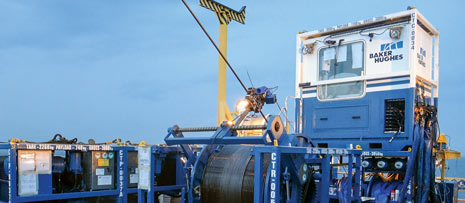
| An offshore, Micro CT operation (image courtesy of Baker Hughes). |
|
In 1962, the first fully functional CT unit (CTU) was developed for the purpose of washing out sand bridges. Throughout the late 1960s, and into the 1970s, service providers continued to improve their designs and developed equipment for CT sizes that ranged primarily from ½-in. to 1-in., outside diameter (OD). By the mid-1970s, more than 200 of the originally designed CTUs were in service. By the late 1970s, several new equipment manufacturing companies started improving CTUs and injector head designs.1 Today, the service has evolved into a multi-billion-dollar global industry.2
The advantages associated with CT are well-published: a workover rig is not required; CT can rapidly trip in and out of the well; and, CT operations can be performed without killing the well. The CT industry continues to be one of the fastest-growing product lines in the oilfield services sector. That growth has been driven by attractive economics, and continual advances in technology, reliability and applicability in an ever-growing list of field applications.
OVERVIEW OF COILED TUBING UNITS
Since its introduction to the industry, CT has evolved from ½-in. OD to 65/8-in. OD tubing, as demonstrated in Fig. 1. From 1999 to 2014, the number of CTUs, worldwide, has increased from 761 to 2,026, Fig. 2.2 The vast majority of these units fit into one of two categories: conventional land CTUs, normally driven to a site, and positioned on the ground near the wellhead area; and conventional offshore CTUs, which are skid-loaded, and transported to location by a vessel. A crane then positions each skid on the deck of the platform, near the wellhead. This crane also may be required to support the operation.
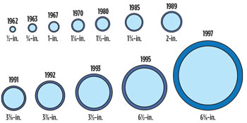 |
| Fig. 1. Coiled tubing pipe diameter evolution. |
|
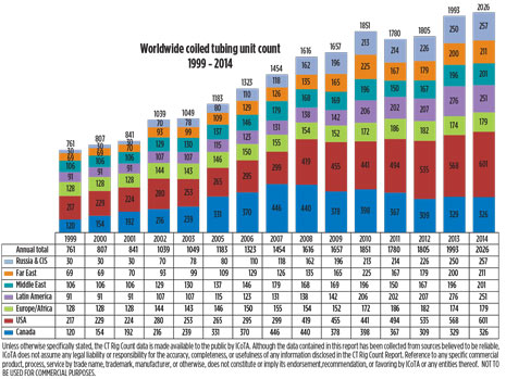 |
| Fig. 2. The growth of coiled tubing units worldwide. |
|
Offshore CTU equipment can be deployed in numerous methods and configurations:
- Platform crane lifts and places the CTU, and associated pumping and support equipment, on the platform;
- In cases where platform cranes are inadequate, temporary, or self-erecting, crane packages lift the CTU and associated equipment onboard;
- CTU equipment is placed on the platform, with pumping equipment staying onboard a support vessel, in cases of insufficient platform deck space;
- A lift boat, barge/tender, or rig supports CT operations, where deck and crane limitations may preclude other options;
- Catenary applications, where deck and crane limitations may be hindering other options, requiring additional equipment or modifications to a standard CT unit.
Many older, marginal or depleted fields have access, deck space and/or crane limitations that restrict the use of larger conventional CTUs. These challenges can make it more difficult to economically justify deploying more costly solutions. In some cases, wells have been abandoned before reaching their potential producing lives, even though smaller CTUs might have helped extend that production—if they had been more readily available.
It is often concluded that a limited-size platform could benefit from the using a small CTU package (Fig. 3), along with a small fluid pump, nitrogen pump and nitrogen tank, especially when the platform crane has limited lift capacity, such as below 5,000 kg.
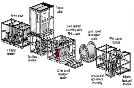 |
| Fig. 3. Small CT unit layout. |
|
The primary driver to perform CT work is typically the production gain potential versus associated operational cost, which is, in turn, influenced by the degree of difficulty to perform the work. Essentially, a matrix summary can be built, focusing on challenges of available deck space, deck loading and crane capacities, along with the nature of the work required. The well owner and engineers may analyze how to evaluate a particular job, based on some simple criteria, and then rank their options to determine which, if any, path to take.
COILED TUBING-RELATED TECHNOLOGY ADVANCEMENTS
The developments made in CT have not been limited to equipment and reliability alone. CT materials, initially manufactured by one company in 1969, exhibited yield strengths between 40 and 55 Ksi. Over time, other manufacturers evolved, and through the 1980s, the typical yield strength values increased to 70 to 80 Ksi,2 which increased further to today’s available grades exceeding 100 Ksi.
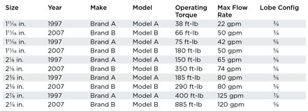
Along with improvements in strength and reliability in the manufacturing process, advancements in downhole tool technology came along. In addition, improvements in fluids—particularly friction and drag reducers—along with the mentioned CT pipe material developments, have now re-opened opportunities for using smaller-diameter CT in intervention applications that historically required larger pipe sizes. For example, fluid friction chemical improvements in recent years have enabled up to 80% friction reduction, thus increasing possible flow rates in small tubulars, such as 1-in. CT.3 In addition, Table 1 demonstrates the advancements CT-sized downhole motors, showing the significant performance improvements made over a relatively short time.
| Table 1. Downhole motor performance examples. |
|
|
Advancements in CT modeling software, to accurately simulate coiled tubing operations, have added advanced computational capabilities to pre-job planning and real time monitoring. Whether the job calls for large CT, small CT or capillary tubing, the modeling analysis is an important engineering and operational step to ensure the most accurate predictions of tubing forces, pressures, temperatures, fluid behaviors, wellbore solids removal and downhole tool operations.3-7
ADVANTAGES AND LIMITATIONS: SMALL CT PIPE
The case for using small CT pipe was studied previously in SPE papers 54456 and 89600.4,3 There are some applications where small CT sizes have a clear advantage over the larger sizes, such as gas lift, particularly in small-diameter completions. There are some key points to understanding gas lifting (Fig. 4), where:
Wellhead pressure = perforation pressure – annular and friction pressures – hydrostatic pressures.
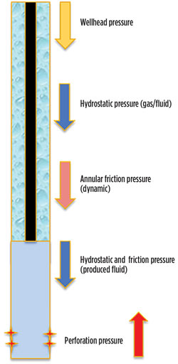 |
| Fig. 4. Fluid and nitrogen ratio affect the hydrostatic pressure, flowrate affects the annular friction pressure loss, and pipe size affects the annular friction pressure loss. |
|
Fluid and nitrogen ratio affect the hydrostatic pressure, flowrate affects the annular friction pressure loss, and CT pipe size affects the annular friction pressure loss. The wrong choice of CT pipe size can act like a significant choke. The nitrogen pumping equipment must also be considered; the minimum pump rate of a standard nitrogen pump may not be low enough to maximize efficiency.
To illustrate the case, a simulation for gas lifting was analyzed, and it is based on a 3½-in. completion with a reservoir pressure of 4,000 psi at 3,500 m (2,810 m, TVD). Two scenarios (Figs. 5 and 6) are shown to compare the effect of using 1¾-in. CT (available choice at location) versus 1-in. CT. This was the only variable changed within the model to illustrate the effect of annular friction.
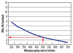 |
| Fig. 5. Gas lift with 1 ¾-in. CT. |
|
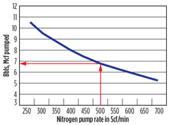 |
| Fig. 6. Gas lift with 1-in. CT. |
|
Comparing the two scenarios, if the job was performed at 500 scf/min, and the objective was to recover 200 bbl of fluid then:
- 1¾-in. CT would take 87 min and consume some 72,780 scf of nitrogen, including the reel displacement.
- 1-in. CT would take 59 min and consume some 39,800 scf of nitrogen, including the reel displacement.
There are considerable advantages to making use of the efficiency aspects of using small CT sizes, in particular, for offshore applications, where all products are most likely to be transported by sea. The additional cost to ship that “extra tank” of nitrogen is often overlooked.
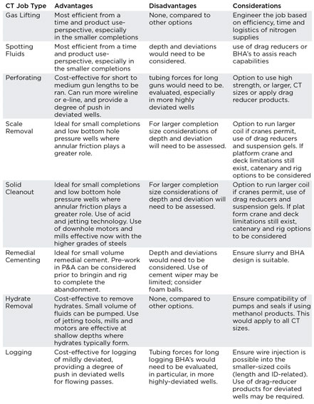
Small coiled-tubing is not always the ideal choice for all applications, and should be engineered properly on a case-by-case basis. Table 2 shows an overview of common CT uses and some example considerations that may be evaluated for the use of smaller coil.
| Table 2. Small CT applications and example considerations. |
|
|
Although not a major focus for this paper, it is important to note that small capillary units and pipe, covering smaller tubing sizes of 1/4, 3/8, 5/8 and 3/4-in. OD have demonstrated increased versatility and application in recent years (due to previously covered technical advancements mentioned already for CT). Capillary tubing has three primary applications and functions:
- Semi-permanent installations for the continuous injection of chemicals downhole for production enhancement;
- Reactivating wells that have been shut in due to the loss of subsurface safety valve control line integrity;
- Wide range of workstring activities similar to those performed by conventional big coil units.8,9
Fully understanding the capabilities of small CT and capillary has resulted in the development of a new and innovative, small CTU package, including associated small fluid and nitrogen pumping equipment further described below. The small CTU package breaks down into nine major components, all with less than 3,000-kg crane lifts. Additional components, such as the nitrogen tank and nitrogen pumping unit, along with a fluid pumping unit, are also less than 3,000-kg lifts. Options exist for the CT drum lifts to be less than 3,000 kg; however, ultimately the weights are subject to the depth of the planned work and CT string design (OD and wall thickness).
SUMMARY OF THE ADVANTAGES OF SMALL CT TECHNOLOGY
The major benefits and attributes of the small CTU package are:
- Compact and lightweight design;
- Modules designed to maintain efficiency in rig-up and rig-down;
- Capable of deploying a wide range of tubing sizes, including 5/8, 3/4 and 1-in. standard package. Larger CT reels and injectors (such as 1¼, 1½ and 1¾-in.) can be used at reduced speeds, due to power pack horsepower limitations;
- Meets Zone II and DNV requirements for offshore operations;
- Reduced logistical support (potential for smaller or fewer vessels);
- Less risk exposure (fewer or no heavy lifts);
- Potential for smaller crew requirements onboard vessels and platforms;
- An alternative, more economic solution to catenary or those operations involving rigs or barges;
- Uses standard pressure control equipment and safety systems, equivalent to a conventional CTU.
The technological advancements in CT metallurgy and fluid dynamics related to friction reduction allow this new “small” application to be considered as a cost-effective alternative to conventional and catenary CTUs. To date, this small CTU concept has been deployed successfully in Southeast Asia for the following applications, which previously would have required more expensive solutions: scale removal, solids clean-out, milling, perforating, and gas lift extension projects. All of these projects are reviewed in the following case histories.
Case History No. 1: Gas lift extension installation offshore Vietnam. A major operator in Vietnam lost all production from one of its highest-producing offshore wells, due to the inefficiency of the originally installed-conventional gas lift system. The matured reservoir could no longer maintain a fluid level high enough to reach the bottom gas lift mandrel. An innovative through-tubing solution was required. Although remaining estimated reserves were substantial, they did not justify the cost of an expensive workover program.
The operator had a window of opportunity to do the installation during monsoon season. Company policy prohibited lifting anything heavier than 5 t off the boat during this period. This restricted the use of a conventional CTU. The decision was made to air-freight the small CTU from the UK, to allow them to meet their time constraints, and stay below the 5-ton load limit restriction.
The service provider custom-designed a gas lift extension system that would straddle the bottom side-pocket mandrel, and direct the injection gas from the annulus down a 1,985-m, ¾-in OD capillary extension into the fluid level below the packer, Fig. 7.
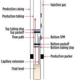 |
| Fig. 7. Customized gas lift extension. |
|
The installation was completed successfully within the given time constraints and under budget. After opening the well, it flowed at rates more than three times the operator’s expectations and original economic justification. The project was completed incident-free in two and a half days and had a four-day payback period.9
Case History No. 2: solids removal onshore Thailand. An onshore operator in Thailand had a new gas discovery, with solids and residue in the 4 ½-in. liner that was covering a substantial portion of the perforated interval. This resulted in the well producing far below the operator’s expectations. Drilling rig components and surface well test equipment leave inadequate rig-up space for a conventional CT system. The well was located in a remote area, with difficult and treacherous road access.
A decision was made to mobilize the small CTU with 1-in. OD tubing to clean out the solids in the liner. Due to the small footprint, the small CTU, high pressure fluid pump, and all other associated equipment to support the project were safely positioned on location. The logistical support required to transport the system to location was substantially less than would have been required for a conventional CT system. This minimized hazard and risk exposure.
The cleanout operation was completed successfully without incidents or accidents. After the cleanout, the well produced at rates higher than anticipated by the operator.
Case History No. 3: scale removal offshore Thailand. A major operator in Thailand had an offshore well with scale problems that could not be removed using slickline methods. The platform deck space was too small to fully accommodate a conventional CT system along with the required flowback equipment. A decision was made to mobilize the small CTU to clean out the scale and return the well to its full production capacity.
The small CTU and flowback equipment were positioned safely on the available deck space. The 1-in. CT, along with a high-pressure rotary jetting tool and 15% HCl, were deployed to clean out the scale obstruction that was inhibiting the production. As a back-up, 111/16-in. PDM (positive displacement) motors with milling tools were provided on location as a contingency. The well was cleaned out in a single trip, from to 10,037 ft to TD at 12,842 ft without having to deploy the milling tools. The actual operating time was four days. This was done at a significant cost savings to the operator as all equipment was positioned on the platform and no barge support was required: no support barge required, at $30,000/day, yielded 30% to 40% savings, compared to conventional
CT operation.
Case History 4: Milling and Perforating Offshore Malaysia. The lower zone of a single gas producer, offshore Malaysia, became inaccessible after the operator set a stacked tubing patch to abandon an upper zone. Several unsuccessful attempts were made with slickline to work through the restriction. Lead impression block runs indicated that the internal diameter of the tubing patch had been damaged, causing a restricted ID (internal diameter). The platform deck space and crane limitations precluded the use of a conventional CTU. A decision was made to mobilize the small CTU, which was small enough to safely position with tanks and pumps in the limited deck space.
The 1-in. tubing, 11 1/16-in. PDM motors and tapered milling tools were deployed to mill through the obstruction in the tubing patch. After milling out the obstruction, slickline runs were made to confirm that the lower zone access was achievable. However, due to the wellbore deviation, the risk associated with perforating with slickline was considered to be unacceptable. The decision was made to carry out the perforating program with the small CTU and 1-in. tubing. To assure depth control, correlation runs were made with a memory gamma ray/casing collar locater tool. Twenty-three successful perforating runs were completed with the small CTU. The well has now been put back on production. The production effect was instantaneous with a gas rate of 15 MMscfpd. The intervention has allowed the client to continue producing the well and access reserves while avoiding the expensive cost of an extensive workover operation.
CONCLUSIONS
Small CTUs and smaller pipe (such as 1-in.) have been used successfully on the following five applications—scale removal, solids clean-out, milling, perforating, and gas lift extension projects. Using CT modeling software, advancements in fluid technology, CT metallurgy and downhole tools, combined with suitable engineering designs now allows for many other applications—hydrate removal, gas lifting, memory production logging, fishing, remedial cementing, spotting chemicals, acid wash, subsurface injection valve replacement options, fiber optics conveyance (logging), and thru-tubing inflatable deployment. Due to the small footprint and light weight of a small CTU (with crane lifts under 3,000 kg each), well interventions that were previously considered uneconomical with larger CTUs or rigs can now be re-evaluated using a small CTU. Thinking small has the potential to increase recoverable reserves in wells that were previously considered for P&A. The small CTU is not meant to replace conventional or catenary CTUs in all situations; however, when crane, available platform space or weather are an issue, the small CTU may allow for adequate well intervention solutions or alternatives. 
ACKNOWLEDGEMENTS
The authors would like to thank Baker Hughes for allowing this article to be published. Special recognition needs to go to Baker Hughes Vietnam, Thailand and Malaysia country personnel who supported field operational efforts as well as the equipment manufacturer and personnel who supported this project from its infancy. This is derived from a paper prepared for presentation at the SPE Annual Technical Conference and Exhibition in New Orleans, La., on Sept. 30 to Oct. 2, 2013.
REFERENCES
- World Oil Coiled Tubing Handbook, 4th edition.
- Intervention & Coiled Tubing Association (ICoTA) website.
- Portman, Lance, “New technologies allow small coiled tubing to complete the work formerly reserved for large coiled tubing units,” SPE paper 89600, presented at SPE/ICoTA Coiled Tubing Conference and Exhibition, Houston, Texas, March 23-24, 2004.
- Portman, Lance, “The science and economics behind coiled tubing string design and optimization,” SPE paper 54456, presented at SPE/ICoTA Coiled Tubing Roundtable, Houston, Texas, May 25-26, 1999.
- Engel, Rae, “New methods for sand cleanout in deviated wellbores using small diameter coiled tubing,” IADC/SPE paper 77204, presented at IADC/SPE Asia Pacific Drilling Technology Conference, Jakarta, Indonesia, Sept 9-11, 2002.
- Terry, Mahajan, Portman, “Modeling coiled tubing drag forces – small factors have a big impact,” SPE paper 89598, presented at SPE/ICoTA Coiled Tubing Conference and Exhibition, Houston, Texas, March 23-24, 2004.
- Craig, S.H., “A multi-well review of coiled tubing force matching,” SPE paper 81715, presented at SPE/ICoTA Coiled Tubing Conference and Exhibition, Houston, Texas, April 8-9, 2003.
- Pate, Stanley, “Capillary tubing advancements for enhanced production and reduced environmental impact – a case history review,” IPTC paper 14595, presented at the International Petroleum Technology Conference, Bangkok, Thailand, 2012.
- Pate, Stanley, et al, “Extending gas lift systems deeper into the wellbore using capillary through tubing services,” IPTC paper 16912, presented at the 6th International Petroleum Technology Conference, Beijing, China, March 26-28, 2013.
|


