Definitive dynamic surveys: A long-awaited engineering innovation
Surveying is an essential part of any wellbore construction project. Wellbore surveying is needed to meet geological targets and avoid other wells, and it can delineate reserves and a reservoir’s geometric composition. The backbone of the wellbore surveying industry is a magnetic reference system commonly known as MWD, which can derive a magnetic north reference with generally three accelerometers and three magnetometers.
Inherent costs are associated with wellbore surveying, including the costs of the survey tools themselves and the rig time associated with acquiring these surveys. Considerable but incremental improvements in tool costs and efficiency have occurred over the last 40 years. Surveying times have dropped, telemetry speeds have increased, and reliability has improved. Fundamentally, however, MWD surveys are taken in the same way today as they were 40 years ago.
In order to take these traditional MWD surveys, the drillstring needs to be stationary without any pipe movement or rotation, trapped torque needs to be taken out by working the drillstring up and down and a survey needs to be pumped up to surface. Equally, the directional driller needs to plot these surveys at surface and decide on the best BHA setting to drill ahead to follow the planned wellbore trajectory. This repetitive task takes time, and even if survey is only taken at every connection, the surveying time can reach days on an extended-reach drilling (ERD) well. Equally, spending time stationary while taking surveys, for additional pump cycles mid-stand in tight anti-collision situations or for BHA response confirmation in a traditional MWD survey, adds the likelihood of drilling risks such as hole cleaning, stuck pipe, and borehole washout.
Additionally, continuous gyro and single-axis continuous MWD inclination surveys have revealed that surveying only once every stand can lead to errors in well placement from a true vertical depth (TVD) perspective. This often leads to a poorer understanding of a wellbore’s true architecture, which can increase the flat times during the well construction process to run casing, complete the well and place artificial lift equipment. Flat time represents a significant proportion of a well’s authorization for expenditure (AFE), especially with the improvements in recent years to on-bottom drilling efficiency.
DDS PLATFORM
With the industry’s focus shifting from on-bottom drilling performance to total well life cycle costs, flat times have become more highly scrutinized during the AFE process and reducing flat time has become increasingly important. In response to this challenge, Schlumberger introduced the TruLink* definitive dynamic survey-while-drilling service, which employs advanced MWD technology to provide an answer to flat-time improvement without compromising surveying accuracy and improves traditional MWD surveys. The technology does this by enabling continuous six-axis surveys while drilling to generate definitive dynamic surveys (DDS). DDSs use three accelerometers and three magnetometers while drilling to derive an accurate inclination and azimuth despite the shock and vibrations from the drilling process. The application of DDS has multiple benefits:
Reduced rig time. The most obvious benefit is reduced rig time. No longer do drillers need to work the pipe to release trapped torque, take the survey, wait for it to be pumped up and then decide on the next steering decision. This saves approximately seven minutes per connection or hours to days for a whole well depending on the wellbore length.
Trajectory control. By continuously being informed of BHA steering performance, the directional driller has improved trajectory control. Every change in steering commands or drilling parameters the resultant direction change can be seen immediately with DDS, with the same accuracy as a static MWD survey.
Stuck pipe risk reduction. The majority of stuck pipe situations are observed immediately after making connections. If the time stationary with the pumps off is cut down, reducing pump cycle times and time stationary with pumps off can reduce the risk of stuck pipe considerably.
Real-time surveys. Having an accurate but dense survey in real time enables an improved understanding of tortuosity and how to run casing and completions, anticipating potential well construction problems in real time, reducing surprises and flat times.
Improved TVD accuracy. Improved TVD accuracy comes with DDS; this assists in the interpretation of LWD images and improves reservoir understanding. Improved TVD accuracy can have a direct impact on production on the current well being drilled and future wells.
Improved hole conditions. Eliminating the need to be stationary to acquire the surveys reduces the hole washouts due to flowing without pipe movement or rotation, which improves borehole conditions. The net results of these DDS benefits are improved drilling efficiency, increased reservoir understanding and reduced drilling risks.
Making DDS possible. Taking a stationary MWD measurement and making it dynamic whilst at least maintaining the stationary survey accuracy is a challenge. These are three main problems to overcome.
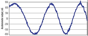
Shock and vibration. The drillstring rotates, vibrates and is subjected to shock while a survey is taken. This can be seen in Fig. 1 where one accelerometer is displaced while the shape of the response can be clearly seen in the individual measurements, which are affected by shock and vibrations. This needs to be compensated for or else the resultant inclination will be poor. Through filtering and algorithmic compensation, the response from the inclinometers was corrected to the point an accurate inclination could be derived.
Attenuations and phase shift. While the tool is in rotation, there are six different sensors measuring the wellbore inclination and azimuth. As an example, if the pipe is rotating at 130 rpm or 3 revs per second, the timing of the sensor measurements needs to be extremely accurate, and attenuation in the circuitry and the sensors themselves must be understood and compensated for in order to have the breadth of sensitivity and frequency response to deal with a very high sampling rate across a large range of rpm.
In order to achieve this, new sensors were designed, electronics were optimized, and a very comprehensive tool calibration was designed to overcome timing issues associated with the dynamic environment the tool is measuring.
EDDY CURRENTS
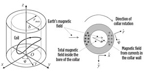
If any piece of metal in the earth’s magnetic field is rotated, it will generate eddy currents. As shown in Fig. 2, these will lead to offsets in the azimuth derived from the tool. The eddy currents are a function of the conductivity of the collar that is rotating, the mass of the collar, the rpm of the collar, and the offset from the collar. This error can be very large, and several degrees of offset can be seen in a 9-in. collar for instance, even at moderate rpm. Thus, it needs to be compensated for.
The most reliable way to do this is to measure the ID and OD and conductivity of the collar and apply these parameters to the firmware of the tool to make a compensation based on rpm downhole. However, this was theoretical, and while it worked well in the lab, a rigorous field test was needed to prove DDS could deliver the required reliability and accuracy.
ACCURACY PREDICTION
An error model with framework designed based upon the standard static error model has helped predict the accuracy of DDS, with one survey taken while drilling and the other taken while static. Three error categories include common error sources with the same magnitude, common error sources with a different magnitude or weighting function, and new error sources due to the dynamic environment while taking the DDS.
The common error sources including depth error, geomagnetic reference error, BHA-dependent error and sensor error were completely unchanged compared with the MWD. The BHA-dependent error showed the most significant amount of change. With the static survey, the effective gravity on the BHA can cause misalignment with reference to the borehole. With rotation, misalignment is likely to decrease, so magnitude was adjusted from 0.08 to 0.06 during testing.
The new error sources for shock and vibration are filtered out while drilling and residual errors affecting accelerometers are modeled as random noise. The ability to filter them enables reaching a more stable inclination value.
DDS is dynamic with time-varying signals read by each cross-axial sensor and is subject to low pass filtering, which must be compensated for because it induces time errors. Differences in the timing between the accelerometer and the magnetometers must also be compensated for and combined to give azimuth. Separate error terms include attenuation from the accelerometers and magnetometers and the phase shift difference between the accelerometers and magnetometers, which provide an accurate idea of inclination and azimuth. All errors are systematic.
Another error source includes eddy currents occurring from rotating metal, which impacts azimuth. The faster the rotation, the higher the eddy current becomes and the greater impact on MWD surveys. Measuring rpm, ID and OD and the conductivity of the metal can enable correction and reduction in eddy current impact.
Another error source is centripetal acceleration effect while rotating. Centripetal acceleration for a fixed but random offset of the accelerometer sensors from the axis of rotation has two primary effects. The first is the effect of the average angular rate over the measurement averaging internal, which will appear as a cross-axial acceleration bias. Since averaging occurs over 2 πm in full rotation, this effect will cancel out.
The second effect acts like random cross-axial acceleration noise even when the variations in angular rates are correlated in time. Due to the intractable nature of the closed-form math, which must account for rotation averaging and integration of a random variable, and the time-correlation of the random variable, the centripetal acceleration partial derivatives had to be derived through qualitative empirical analysis. The form matches that of the cross-axial shock and vibration noise. Depth shift compensation drilling at high rpm introduces a small delay in inclination and azimuth, which causes an error in inclination and azimuth. A magnitude of 0.08 at high rpms and tight doglegs has proven adequate for most drilling.
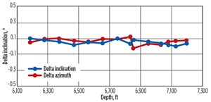
Field testing. An analysis of 20 runs compares the delta inclinations between the DDS nearest to the static survey and the delta azimuth, Fig. 3. They are 0.1 of a degree or below, which are small errors and well below expected errors in comparison of two MWD surveys. The standard static MWD model is fit for purpose and the DDS all falls within the EOU of the static MWD error models, validating the quality of the DDS error models.

System accuracy from a sensor perspective showed between 0.5 of a degree for azimuth. The DDS shows the standard deviation between azimuth is below 0.5 of a degree, proving the DDS and static surveys are of comparable quality and are even better when looking at inclination. A nominal inclination accuracy is 0.1 of a degree, proving effectiveness of inclination measurement compared to the static surveys.
CASE STUDIES
An operator in the Middle East wanted to minimize excessive wellbore tortuosity in a complex well profile and avoid excessive casing wear, stuck pipe, and premature downhole equipment failure, which would increase well costs and decrease productivity. The operator used the definitive dynamic survey-while-drilling service to take measurements from every point of the well, which enabled real-time steering adjustments and resulted in better wellbore positioning and placement of the well 10 ft below the reservoir top. This reduced dogleg severity and created smoother curves and laterals in the complex well profile. Comparison between stationary-survey data and definitive dynamic survey data revealed a 10-ft difference while landing the 8½-in. curve section.
In another well, the same operator in the Middle East wanted to reduce or eliminate surveying rig time to improve drilling efficiency, minimize drilling stuck pipe risks caused from stationary pipe, and improve well economics. The operator identified three wells as official qualification runs that included a vertical, curve, and lateral well profile. The qualification run objectives were to plot the definitive dynamic survey-while-drilling service and gyro-survey data and compare inclination and azimuth values and trends.
The first qualification run was in a vertical section using a rotary BHA, and the total footage drilled was 1,652 ft. Total pumping time on the tool was 28.65 h. Definitive dynamic surveys were acquired throughout the run. At section TD, a drop-down multishot-gyro survey was run, and 44 gyro surveys were acquired. The DDS data and gyro-survey data were plotted against each other. The second qualification run was in a curve section, building from zero to 90° inclination. The BHA included a PowerDrive Xceed* ruggedized RSS to drill 2,862 ft over 137 pumping hours. Surveys acquired with the definitive dynamic survey-while-drilling service totaled 805 compared with 24 drop-down multishot-gyro surveys. Comparison between the dataset inclination and azimuth trends indicated close matches.
The final qualification run was in a lateral section drilled with a motor BHA for 1,000 ft over 42 pumping hours. The definitive dynamic survey-while-drilling service acquired data from 110 surveys. Compared against 311 pump-down gyro continuous multishot-survey data, the result was a perfect match.
CONCLUSION
The ability to continuously survey at every point in the wellbore opens new opportunities for operators compared with traditional static MWD surveys. Improved survey accuracy enables better well placement. By eliminating survey-related rig time, the definitive dynamic survey-while-drilling service increases drilling efficiency and creates significant cost savings. Real-time insight of borehole conditions reduces drilling risks and helps operators reach TD more efficiently. The robustness of the DDS error model and the comparable quality to static surveys enables replacement of the static surveys with DDS going forward.
Ultimately, DDS reduces flat time for any operator. While there have been improvements in ROP, rig technology with soft torque and increased power, this has not really reduced flat time, only operational time. Casing and completions still need to be run and cementing still needs to be performed. This is done, though, in the absence of data at a high enough fidelity to enable problems to be seen with the wellbore architecture.
The use of DDS provides a level of fidelity that has not been possible previously while drilling, enabling informed decisions to be made about casing and cementing prior to running in hole and optimizing casing running procedures and casing volumes. This will positively impact flat time, reducing costs and maximizing accurate well placement in the reservoir.
*Mark of Schlumberger
- Digital transformation/Late-life optimization: Harnessing data-driven strategies for late-life optimization (March 2024)
- The reserves replacement dilemma: Can intelligent digital technologies fill the supply gap? (March 2024)
- Digital tool kit enhances real-time decision-making to improve drilling efficiency and performance (February 2024)
- Digital transformation: Digital twins help to make the invisible, visible in Indonesia’s energy industry (January 2024)
- Driving MPD adoption with performance-enhancing technologies (January 2024)
- Digital transformation: A breakthrough year for digitalization in the offshore sector (January 2024)


