Advances in powered rotary steerable systems result in record-breaking runs
Optimized drilling systems include not only matched drilling tools, but also the integration of technology, processes and people across all stages of the drilling process.1 This combination is important, as the industry looks to improvements to drilling programs to reduce nonproductive time (NPT); improve safety and efficiency; and optimize production.
Fit-for-purpose bottomhole assemblies (BHAs), together with a wide array of advanced downhole drilling tools, have greatly improved drilling efficiency and allowed much-higher ROPs. Choosing the proper drilling system is critical for boosting the well construction process and pushing the drilling limit. Proper BHA design and modeling is critical to the drilling of a well, and contributes to the optimization of drilling efficiency.
Delivering power downhole, without increasing the rotary speed of the drillstring, is a demand in some applications. Operators drilling extended-reach wells do not want to cause excessive wear on casing strings; they also want a solution to mitigate stick-slip. Through-motor telemetry (TMT)-powered RSS is bringing these—and other—benefits to the drilling process.
APPLICATIONS
TMT-powered RSS has a broad range of applications, focused mainly on performance and mitigating certain drilling phenomena, such as vibration. Because of the wired connection and the modular design, drilling optimization or formation evaluation sensors can be incorporated in front of the wired motor, providing great versatility to the BHA configuration.
From a performance point of view, TMT-powered RSS increases ROP, decreases vibration, and decreases casing wear by delivering the torque directly to the bit. The power section decouples the drillstring from the RSS, eliminating torsional vibration, which is common in RSS applications. This benefit increases reliability, not only for the RSS, but also for all of the electronic sensors in the string, including optimization and formation evaluation sensors. In addition, the bit lasts longer and can deliver better ROPs.
An important application for TMT-powered RSS is in instances where a rig experiences limited capacity, related to the top drive’s power to rotate the drillstring, or drill pipe torque limitations. The use of a TMT-powered RSS can, however, reduce stress on a rig and decrease wear on both the top drive and the drill pipe. Extended-reach drilling (ERD) and complex well profiles are classic applications for TMT-powered RSS, by reducing surface torque and increasing reach capabilities.
A TMT-powered RSS allows a variety of sensor combinations, for multiple applications, including geosteering, performance drilling, and reduced stick-out in casing-while-drilling (CWD) applications.
BENEFITS
A number of benefits are derived from TMT-powered RSS. These include:
- More energy is applied directly to the bit, improving cutting efficiency and ROP, while also overcoming stick-slip and torsional-related dysfunctions.
- Decoupling of the bit from the drillstring reduces the transmission of vibrations to the LWD system and other BHA components, thereby improving system life.
- Drillstring rotary speed can be reduced to minimize casing wear, while bit speed is optimized for the best drilling performance.
- When applied in the proper drilling environment, TMT-powered RSS improves ROP and reduces NPT, allowing crews to drill faster and with less risk, resulting in decreased costs.
- Improved ERD capabilities and exposure of the pay zone, which can greatly reduce capital expenditure.
- The TMT-powered RSS can increase ROP significantly in conditions where a rig top drive does not provide adequate torque and surface rev/min.
TMT MOTOR DESIGN
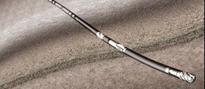
An RSS generally requires communication with the measurement-while-drilling (MWD) system to transmit directional control information to the surface, and to transmit directional commands from the surface to the RSS. Directional information from the RSS is critical for the directional driller, to help ensure that the well is drilled in accordance with the directional plan. Communication between the RSS and the MWD system is also required to send formation evaluation information from sensors in the RSS to the surface. An example is the azimuthal gamma ray sensor in the RSS. Wiring the RSS motor allows transmission of power and high-speed communications between the RSS and the MWD system. The power section is designed for high-torque, low-speed operation. Figure 1 shows a schematic of the main TMT components.
The main challenges in the wired motor design include compensating for the eccentric motion of the rotor in the power section; passing the transmission section and the bearing pack; and compensating for the different rotational speeds between the rotor and upper housing.
TMT MOTOR DESIGN FEATURES
The rotor in a power section has an eccentric, axial motion that is a function of the lobe configuration; the fewer the lobes, the higher degree of eccentric motion. When passing a conductor, from the top of the rotor to the top of the motor housing, this eccentric and axial motion must be compensated for. The method employed is to use a mechanical compensator that compensates for movement in the axial and radial directions, while providing a bi-directional, continuous conductor for power and communications transmission.
Rotation also must be compensated for, because the rotor is decoupled from the upper housing in the rotational sense. A slip ring is employed, to allow for the differential rotation while, at the same time, providing a conductor for stable power transmission and for high-frequency, high-speed communications.
The TMT motor design employs a titanium flex shaft to transmit rotation from the power section to the driveshaft. The flex-shaft design allows for the incorporation of a solid conductor through a bore in the center. In addition, the titanium flex shaft provides high torque capability to drive higher loading below the wired motor.
The TMT motor has the flexibility to use virtually any conventional power section, provided the torque and rev/min. specification is within the tool limits and application requirements. The preferred power section type is uniform wall thickness. The uniform wall thickness power section provides higher torque output and a higher temperature rating. Higher torque capability will allow for smoother rotation of the RSS, and enable drilling at a higher ROP. In addition, the uniform wall thickness expands with temperature at a constant rate. Thinner rubber thickness, which expands at a constant rate, means that the rotor and stator can be fit precisely for high-temperature application; this allows application of the TMT technology at temperatures up to 175°C.
WIRED MOTOR–RSS BHA DESIGN
The placement of a motor in an RSS assembly requires consideration of the impact on the MWD system, as well as RSS and BHA performance. The system described here is modular in design, which allows flexibility in the placement of the motor in the BHA. The motor can be placed between the RSS and MWD system, or within the modular MWD components.
The optimum placement of the power section is, normally, directly on top of the RSS and below the MWD system. This placement allows torque to be delivered directly to the RSS; facilitates higher bit speed without over-rotating the MWD; minimizes the amount of string below the power section; and decouples vibration to the MWD and upper string.
The BHA also can be designed with drilling optimization sensors or LWD sensors located below the motor. Placement of the drilling optimization sensors below the motor, and above the RSS, can be used to measure torque, weight-on-bit (WOB), and bending-on-bit, for example, directly above the RSS for drilling optimization. LWD sensors can be placed directly above the RSS, and below the motor, to obtain measurements closer to the bit.
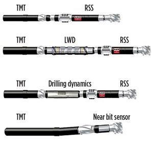
The wired motor also can be configured with a bent housing for conventional motor applications, allowing power and communication to the bottom of the motor and placement of sensors directly on top of the bit. Typical applications include ranging sensors for intersection wells and LWD sensors for near-bit formation evaluation. Figure 2 shows some BHA configurations, depending on the application.
CASE HISTORY 1
Offshore deepwater UK. TMT-powered RSS technology was used by an operator in a high-pressure, high-temperature (HPHT) development well in the UK central North Sea. The challenge included maximizing ROP through hard chalk/limestone formations in the 12 1/4-in. section, and then drilling the 8-in. hole section through an HPHT reservoir using LWD, eliminating the need for wireline.
In the 12¼-in. section, the TMT RSS assembly was used to drill from 5,276 ft to 13,938 ft measured depth (MD). The average penetration rate was 78.6 ft/hr, a 62% improvement over conventional RSS performance in an offset well. Total footage drilled was 8,662 ft, with zero NPT.
In the 8 1/2-in. section, the HPHT TMT RSS BHA, with HPHT LWD quad combo, delivered the entire 2,323-ft section in a single run, intersecting all geological targets with zero NPT. In what was the fourth-longest section in the UK, for drilling hours on bottom since records began, the LWD quad combo was downhole for 355 hr (14.8 days) with 296 circulating hr (12.3 days). Successful LWD performance eliminated the need for wireline logging, and the well reached TD at 16,232 ft, 25 days ahead of plan.
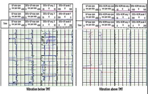
A major benefit of TMT technology, in this case, was decoupling the BHA to reduce vibration on the LWD and upper string. This reduces damage and potential NPT, while simultaneously improving ROP and drilling performance. Figure 3—a time-based log—shows that, while some torsional resonance vibration exists below the motor, it is not transmitted to the LWD tool and drillstring above.
In this particular case, two downhole vibration sensors were part of the drillstring—the first between the RSS and the TMT motor, with a second one behind the TMT motor within the LWD system. The left graph in Fig. 3 is the data from the sensor below the TMT. It shows, in track #4, high average values of vibrations on both the Y and X axes. On the other hand, the right graph, in the same track (sensor above the TMT), shows minimum—or null—average vibration values on both the X and Y axes. This is the decoupling effect from the TMT motor, which reduces the transmission of vibrations.
The vibration measured below the TMT motor was -5.0 g average, x-y delta torsional resonance. The vibration measured above the TMT motor was -0.5 g average x-y delta torsional resonance, indicating a reduction, due to the decoupling effect.
CASE HISTORY 2
Continental Europe exploratory campaign. In this vertical drilling application, the TMT-powered RSS delivered maximum performance, outperforming the benchmark well in the area with RSS or performance motors. During a four-well exploratory campaign, different drilling systems were used, with the aim of maximizing ROP. The structural setting in this project corresponds to ancient Paleozoic and Mesozoic depositions. Because of limited drilling, not much information was known at the beginning of the project.
A geological proposal, however, identified a hard/abrasive drilling environment, multilayered dipping, and folded formations with dips in the range of 40º to 70º. The stratigraphy of this area corresponds to the old Mesozoic and Paleozoic geological eras, starting with the Cretaceous period, subjacent by Jurassic, Devonian, Silurian and Cambric. On top of the hardness and abrasiveness, the geological cross-section shows important discontinuities with highly faulted events.
The first well was drilled with a rotary BHA, including a straight mud motor. Low ROP was experienced, and the hole inclination drifted until reaching an equilibrium angle of around 20º. The drilling continued, with the hole deviation moving in the 10º-to-20º range of inclination. The equilibrium angle depends on various factors, including formation dip angle, drillability anisotropy and drilling parameters in use. The well reached TD with 13º of inclination, and a vertical section of 270 m.
For the second well, a drilling motor was used with both sliding and rotating drilling modes in both intervals (121/4-in. and 81/2-in. hole sizes). ROP was lower, compared to the first well, because of the directional work to keep the well close to vertical. The abrasiveness of the formation necessitated several trips to drill each interval.
Another well used a push-the-bit vertical-seeking tool powered with a motor above it. This approach managed to drill the well vertically and improve ROP. Still, some drilling inefficiencies were experienced, including vibration, which reduces a bit’s life.
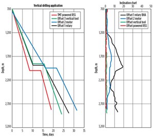
The last well incorporated a point-the-bit RSS, together with a wired power section to drill both the 12 1/4-in. and 8 1/2-in. intervals. The TMT-powered RSS system not only managed to keep the well close to 0º inclination but, because of the vertical cruise control mode in use, time was optimized by drilling the well in automatic vertical mode, maximizing ROP. Figure 4 (left) shows the drilling time curve for the four exploratory wells. The TMT-powered RSS also shows value to keep the well vertical. Figure 4 (right) shows the deviation survey for the four wells.
During the entire run, the TMT-powered RSS observed a strong build tendency, caused by the steeply dipping formation. The TMT-powered RSS was operated with bit deflection over 60%, and mainly at 80% to 90%, to keep the wellbore vertical.
Vibration mitigation measures were employed at the direction of real-time engineering monitoring. However, low-to-medium vibration severity was still present while drilling in the presence of interbedded formations; medium-to-high vibration also was present when picking up the bit off bottom.
CASE HISTORY 3
Middle East hard formation. A mature field application in Kuwait required TMT technology to improve ROP in a hard formation. The well consisted of build and land sections in an 8 1/2-in. hole, followed by a lateral section in a 6 1/8-in. hole. At the same time, a high degree of steerability was required because of geologic uncertainty. TMT technology, along with high-build-rate RSS, was chosen for this application.
In the 8 1/2-in. section, high build rate was required at landing because of formation tops coming in high. The required trajectory was achieved with record ROP in this field, a 60 ft/hr average, including connections and reaming times. A total of 2,500 ft was drilled, building the angle from 4° to 88° inclination in hours versus the 3.5 days planned for the section.
In the 6 1/8-in. lateral section, the assembly included a TMT-powered RSS and LWD tools, including a geosteering service to navigate through the reservoir. The assembly drilled the reservoir successfully for 1,500 ft, and then steered into the secondary reservoir by dropping the angle to 84° and steering inside that zone for approximately 900 ft. With an average ROP of 36.4 ft/hr in the 6 1/8-in. lateral section, this run also established a field record. Figure 5 shows the trajectory created.
In the build section, alone, a field-record average ROP of 59.60 ft/hr saved the operator two days, or approximately $100,000, while in the 6 1/8-in. section. The geosteering assembly achieved a field-record average ROP of 36.4 ft/hr to save the operator another 3.5 days, or about $175,000.
CASE HISTORY 4
Unconventional play. Drilling efficiency requires attention to a variety of key indicators. Modeling BHAs, together with advanced drilling technologies, contributes to the stability of the drilling system, optimum performance and, ultimately, improvement in efficiency. The fourth case history was in an unconventional play, in which a TMT-powered RSS was used to drill a long lateral section, performing better than the best well previously drilled using mud motors.
The lateral hole intervals traditionally had been drilled with motors, achieving an ROP of 50 ft/hr to 70 ft/hr. Lately, however, RSS’s were introduced to drill long, lateral, complex trajectories, which has resulted in increased ROP. The objective of this well was to use a TMT-powered RSS to navigate through the best-quality rock, while matching/exceeding the established benchmark ROP as a minimum.
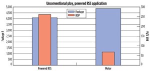
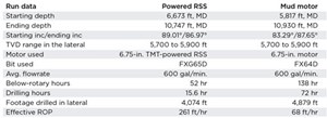
A TMT-powered RSS assembly was used to drill the 8 1/2-in. lateral section of the well. Total footage drilled was 4,074 ft, MD, in one run. Table 1 shows relevant data from the powered-RSS application and presents run data, comparing a TMT-powered RSS to a motor.
In total, the TMT-powered RSS drilled 4,074 ft along the shale formation while geosteering, and achieved good-quality rock, based on formation evaluation data in real time. The effective ROP was more than four-fold, as compared with the ROP experienced in offset wells. The improved ROP, achieved by using the TMT-powered RSS, saved 24 hr of rig time. Figure 6 shows the comparison of a TMT-powered RSS and the best offset mud motor run.
The matched, uniform, wall thickness power section powering a point-the-bit RSS improved steerability and reduced inefficiencies. Producing the power and speed, as well as torque, closer to the bit results in better steerability and better wellbore quality. This led to a record lateral in terms of ROP.
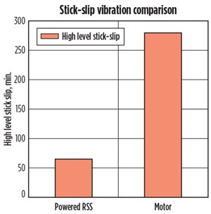
Drilling efficiency improved, as vibration-related damage was reduced by minimizing stick-slip and by decoupling the LWD tools from damaging shocks and torsional vibration. Some vibration was experienced with the TMT-powered RSS, mainly during circulation out of bottom. Figure 7 shows a comparison of vibration experienced with both systems.
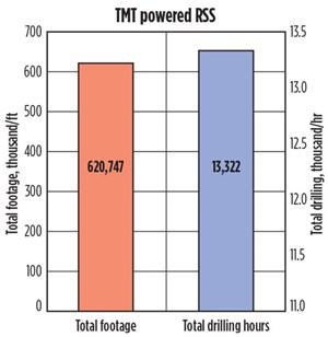
The TMT-powered RSS has been a drilling efficiency step-change.2 Proper planning—in the right application—can deliver great benefits for well construction. Figure 8 shows 2013 footage and drilling time using TMT technology.
CONCLUSIONS
The TMT-powered RSS showed improved performance, as a result of increased torque capacity and bit speed, and reduction of the stick-slip mechanism. It has delivered superior performance and improved ROP, in challenging medium and hard formations.
TMT wire technology is the most reliable way for a high speed and power communications between the RSS and the MWD, allowing for BHA design flexibility to accommodate placement of downhole sensors ahead of the power section.
In a vertical drilling application, the TMT-powered RSS has delivered maximum performance, outperforming the benchmark well in the area, in comparison to RSS alone or performance motors. The matched, uniform, wall thickness power section powering a point-the-bit RSS improves performance significantly in hard formations and HPHT applications. ![]()
ACKNOWLEDGEMENTS
The authors thank the management of Halliburton for their support of this project and encouragement to publish this work. This article is an adaptation of SPE paper 169348-MS.
REFERENCES
- Alvord, C., B. Noel, L. Galiunas, et al, “RSS application from onshore extended-reach development wells shows higher offshore potential,” OTC paper 18975-MS, presented at the Offshore Technology Conference, Houston, Texas, April 30–May 3, 2007.
- Zimmer, C., J. Pearson, D. Richter, et al, “Drilling a better pair: New technologies in SAGD directional drilling,” SPE/CSUG paper 137137, presented at the SPE/CSUG Canadian Unconventional Resources & International Petroleum Conference, Calgary, Alberta, Oct. 19–21, 2010.
- Coiled tubing drilling’s role in the energy transition (March 2024)
- Digital tool kit enhances real-time decision-making to improve drilling efficiency and performance (February 2024)
- E&P outside the U.S. maintains a disciplined pace (February 2024)
- U.S. operators reduce activity as crude prices plunge (February 2024)
- Drilling advances (January 2024)
- Driving MPD adoption with performance-enhancing technologies (January 2024)

