The only thing constant is change. Never has this been truer than with the centralization of casing strings for well construction.
Traditionally, wells were constructed by drilling wellbores and setting casing strings with each subsequent section of the well, telescoping smaller as the well went deeper. This meant that the centralizers, used to keep the casing off the wellbore during cementing operations, only had to enter a previous casing with a larger inner diameter, or ID, before squeezing into the smaller open hole of the newly drilled section. When drilling technology evolved to the point of achieving deeper, extended reach capabilities in deepwater, the need to under-ream and keep casing IDs as large as possible, for as long as possible, became common-place.
The technology for centralization fell behind the pace of drilling technology. The performance of traditional bow spring centralizers, when going from smaller IDs to larger IDs, was problematic under these new conditions. API Spec 10D (the standard for centralizer performance) was not designed, such that tool manufacturers would report centralizer data to help model real-world conditions under these circumstances.
A FRESH PERSPECTIVE NEEDED
It took someone with a fresh perspective and motivation to recognize this inadequacy and, therefore, enable its solution. The solution required developing a centralizer sub that not only solved performance issues of larger, under-reamed holes, but also allowed rotation, as needed, with the bow springs in any state of flex, Fig 1.
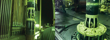 |
| Fig. 1. New rotating centralizer sub design in action. |
|
This rotating feature proved to be remarkably innovative, because in traditional centralizer designs, the bow springs could come in contact with the casing, making rotation treacherous for both the casing and the centralizer.
On many traditional centralizers, bow springs are joined to the end bands by welding them into a notch stamped out of the end band. This style assembly cantilevers the heel of the bow spring just above the surface of the casing in the un-compressed state. Once deflection of the bow begins, as it enters a restrictive ID, contact is made between the bow heel and OD of the casing.
The heel, acting like the fulcrum of a lever, digs into the surface of the casing, essentially applying a braking action to resist rotation. As more deflection occurs, in even smaller IDs, more braking action is generated by the contact point, increasing the potential for damage to the casing or sub body, as rotation is attempted.
The new design solves this situation by leaving the heel of the bow spring over the end band, therefore transferring the fulcrum force only to the end band and not the casing or rotating surface, Fig. 2. This leaves the casing string free to spin within the end bands that are absorbing all of the contact force from the bows.
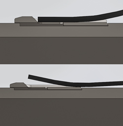 |
| Fig. 2. Fulcrum principle with heel contact remaining on end band vs. on the casing |
|
This innovation was evident on a deepwater Gulf of Mexico well in 4,500 ft of water. The well was originally drilled to TD in the 27,000-ft range, with a subsequent window cut in 97/8-in. casing around 25,800 ft.
A sidetrack hole was drilled to 27,300 ft, where approximately 1,800 ft of 75/8-in. liner was run using Blackhawk centralizer subs on every joint of the liner. During the trip-in, the top drive system developed issues, halting the liner running operation for several hours with the liner still inside the 97/8-in. string.
The 97/8-in. liner had an 8.531-in. ID with an 8.500-in. drift, resulting in a 0.453-in. annular clearance with the 75/8-in. liner and subs. Once the top drive was repaired, the liner with subs was rotated inside the 97/8-in. liner at 20 rpm under 10,000 ft/lb of torque on the way to bottom.
At the window exit point, no additional drag or torque was noted, as the liner exited the window. With just 100 ft to go, and the liner completely across a sand section, the top drive again went down and took an additional hour to repair. Upon completion of this second repair, the liner was able to be washed and then rotated the remaining 100 ft to bottom, giving testament to the performance of the centralizer subs for both stand-off (prevention of differential sticking) and true rotating capabilities at compatible torques.
The result: a liner that was run to TD and cemented successfully with rotation, as verified by a bond log across the liner section. Being able to rotate a casing string, or liner, often means the difference between getting the string into position or not. API 10D, to this point, has not addressed such issues. Now there is a need to re-evaluate centralizer testing standards, how centralizer data are published, and how they are used by operators.
ACCURATE MODELING REQUIRED
Cementing operations require accurate modeling for ideal results. Accurate modeling of a casing string in a certain wellbore scenario requires real performance data for the exact conditions. Gone are the days of a single data point at 67% standoff, as traditionally published per API 10D. What casing placement simulation and modeling require in today’s industry are accurate performance curves, so that varying conditions can be estimated properly, Fig. 3.
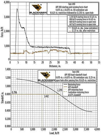 |
| Fig. 3. Varying conditions on casings can be estimated properly using placement simulation and modeling. |
|
The actual starting and running forces that will be encountered when running the casing string through the various IDs can be critical information for planning and executing a cost-effective well.
The industry has been looking for a reliable data solution to maintain adequate annular clearance for good mud removal and cement placement. This is another critical component in planning centralizer placement in the string. Until now, traditional data were often estimated, ignoring the transformation that can occur to the resorting forces after passage through tighter restrictions.
This undoubtedly has plagued the industry in the past with less than desirable results, without cause-and-effect explanation.
Bow spring centralizers utilize specialized leaf springs to generate restoring forces. It was recognized that an in-depth study of taking these springs completely flat would be required to improve performance. This type of study involved the use of modern stress analysis tools such as Finite Element Analysis (FEA) and empirical data obtained from actual stress strain testing of individual bows.
Armed with the results of such studies, engineers were able to model the springs in a virtual world, and put them through various iterations of optimized shapes and cross-sections while flexing them throughout their total range. The results minimized stresses that altered post-flex geometry of the springs and ultimately maximized the residual spring force, i.e. centralizer restoring force potential, Fig. 4.
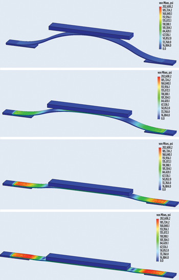 |
| Fig. 4. FEA modeling cycling from free height to fully flexed. |
|
Bow spring centralizer subs not only have to perform in the restoring force area, but also must meet the properties of the casing string. The body of a centralizer sub is essentially a pup joint of casing with a built-on centralizer. However, because of the required interaction of the centralizer and the sub’s geometry, the sub body cannot be made simply from match-grade casing.
ENGINEERED PRODUCTS EXCEED COMPLIANCE
This means that significant engineering must be employed to specify exacting dimensions and mechanical properties of the materials used in their production for each application. With this product being engineered to order, often the margins of standard practice would have to be explored to enable compliance to requirement.
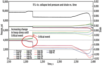
For example, cross-checking calculations to examine all potential modes (elastic, plastic or transitional) of collapse failure are often necessary to more accurately predict performance, rather than simply relying on the standard conservative industry formulas. Testing proved that this approach was valid for normal design cases with adequate safety margins, and also confirmed that non-linear FEA was able to accurately predict actual collapse for extreme design cases, when safety factor margins were too close to relying solely on calculations, Fig. 5.
 |
| Fig. 5. Pressure and strain graph, zoomed (critical event). |
|
The challenges of meeting today’s well construction requirements are often demanding. However application of new technologies to engineering practices is proving successful in modernizing some past stagnant designs, such as centralization.
Armed with a better understanding, proper engineering tools and updated standards, the oil and gas industry can now tackle even more cementing challenges. 
|


