Recent developments in wireline logging and formation evaluation
Part 2. Wellsite evaluation is experiencing a revolution with the development of ruggedized hand-held analyzers and automated mineralogical analysis in real time. New techniques are also available for core handling and laboratory analysis. In the new digital rock physics discipline, CT imaging systems are now available with nanometer resolution for exceptional insight into core microstructure.
STEPHEN PRENSKY, Consultant, Silver Springs, Maryland
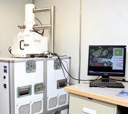
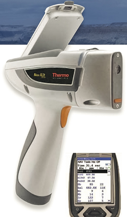
The purpose of this article, which is based on published technical papers and publicly available literature, is to inform readers of new and potential technologies in well logging and formation evaluation. This article does not endorse or promote any particular technologies or service providers. Some of the technologies described in this article may be currently available as commercial services, while others may still be in the development or test phases. WELLSITE EVALUATION Mud logging. Significant advancements in mud-gas extractors, in conjunction with the development of ruggedized, portable analytical devices, have resulted in a quantum improvement in 1) reliability and repeatability of mud-gas analyses, and 2) near-real-time, laboratory-quality, quantitative determination of rock properties at the wellsite. These developments allow rapid characterization of reservoir rocks and fluids that benefits decision-making regarding well placement and completion. Advanced gas extractors offer constant volume and temperature extraction of gas-in-mud. Combining these data with gas-analysis spectrometers enables reliable real-time determination of gas-in-mud, characterization of formation fluids, and improved managed-space needed between pressure and drilling.1-3 An important trend in formation evaluation has been the development of benchtop and handheld analyzers and their integration in wellsite evaluation. These analyzers offer nondestructive methods that enable multiple and diverse physical measurements to be made on the same sample. Combining the improved accuracy, precision, and reliability in traditional wellsite equipment with the recent availability of laboratory-quality analytical devices adapted for wellsite use, service companies can now provide detailed mineralogy and a full range of rock and fluid property analyses in real, or near-real time, while drilling. These include improved monitoring of drilling parameters, enhanced cuttings analysis through high-resolution image acquisition and processing, and physical and geochemical measurements on core samples and cuttings. Measurements include grain density, spectral gamma ray, magnetic resonance imaging (NMR), X-ray diffraction (XRD), X-ray fluorescence (XRF), and source-rock analysis.4-6 Automated quantitative mineralogical and rock properties analysis. Particularly in shales, reservoirs with complex mineralogy, or homogeneous formations that lack micropaleontologic markers, a determination of the mineral composition (through chemical composition or elemental analysis) is essential for achieving accurate stratigraphic correlation (chemostratigraphy) and reservoir modeling.7-9 Mineralogy is also related to porosity, permeability, TOC and brittleness, and therefore, an essential element in completion design. Several companies now offer wellsite versions of systems that provide automated, quantitative mineralogical, lithological and textural analysis of drill cuttings. Data are provided in near-real time, and are particularly valuable for real-time calibration of wireline and LWD logs and use in well placement/geosteering. These services include the Chemostrat/Halliburton LaserStrat system6 (see 2010 article), FEI’s QEMSCAN wellsite system, and Fugro Robertson’s RoqSCAN system. The QEMSCAN system10, initially developed by CSIRO for the mining industry and currently marketed by FEI, is now available in a portable wellsite configuration for analysis of drilling cuttings and core samples.11 This automated mineralogic analysis system is a combination of a scanning electron microscope (SEM) and electron dispersive spectroscopy (EDS), with automated analysis software that uses BSE (backscattered electron intensity) and EDX (energy dispersive X-ray) spectra for rapid image analysis and data acquisition for thousands of grains in a short time, enabling identification of the mineralogy, mineral variation and distribution (i.e., mapping), and grain shape. Prepared samples for analysis consist of polished sections from cuttings, polished thin sections from cuttings or core, and solid core. The system creates mineral compositional maps of the sample surface. The RoqSCAN system12 consists of a ruggedized base-scanning electron microscope equipped with energy-dispersive X-ray detectors, a microanalyzer, and an electronic processing unit that uses O&G-specific software interpretation tools. This system performs direct measurements on cuttings, sidewall cores, or hand specimens. Point-by-point analysis enables this system to distinguish more than 96 minerals and accurately differentiate clay minerals and clay-mineral phases. Cuttings samples can be analyzed within an hour of arrival of the cuttings, including 20 min. for sample preparation. The results consist of detailed petrographic-style analyses, providing matrix properties, such as bulk mineralogy, lithology, clay type, matrix density and grain size. In shale reservoirs, the software can identify brittle zones, i.e., potentially productive zones. X-ray fluorescence. Energy-dispersive X-ray fluorescence (ED-XRF) analysis is a nondestructive analytical technique that provides accurate and quantitative determination of major and trace element concentrations in a wide variety of materials. It is a fast and inexpensive technique that requires relatively little sample preparation, provides moderately rapid measurement times, and can measure a wide range of elements (Na to U) simultaneously and over a wide range of concentrations. A rock sample is excited using a primary X-ray source (e.g., rhodium, molybdenum), which results in the emission (fluorescence) of secondary X-rays with energies that are characteristic of the elements in the sample. Elemental concentrations can then be determined from the intensities (count rates) of the X-rays at each energy level and quantified using known standards. A typical 1D line scan measurement can require up to 60 s per location.12 XRF scanning is used to assist in core orientation—a normalized X-ray density log of an entire core can serve as a proxy for bulk density.14 XRF provides rapid and inexpensive elemental and mineralogic analysis of geological samples (core and cuttings).6 XRF mapping of sediment cores is used to achieve insight into the spatial and temporal variations in the geochemical makeup and origin of sedimentary structures.13,15 Portable benchtop and handheld rock analyzers. Rapid and inexpensive elemental and mineralogical analyses of rock samples (core and cuttings) and fluids can now be conducted in real time at the wellsite, using a variety of lightweight, portable, benchtop XRF, XRD and NMR analyzers available from a variety of manufacturers, such as Bruker, Rigaku, Spectro and ThermoFisher Scientific. Saudi Aramco has integrated a portable XRF analyzer with the mudlogging unit, in order to integrate direct measurements on drill cuttings with LWD measurements. The results from the portable XRF device are in good agreement with lab-based XRF instruments, and the modeled mineralogy from whole-rock geochemical data is in good agreement with mineralogy determined from X-ray diffraction analyses.6 Some of the providers of benchtop equipment also offer ruggedized handheld XRF16-18 and Raman spectroscopy19 analyzers for use in the field. These devices can provide rapid and accurate elemental analysis and bulk mineral composition of a rock sample, Fig. 1).20
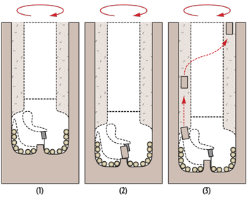
CORE ANALYSIS TECHNOLOGY Microcoring bit. Total holds the patent on a unique diamond-impregnated PDC coring bit that can provide microcores continuously while drilling. The system is undergoing field trials. The objective of this system, which has been specifically designed for deepwater research drilling, is to recover higher-quality drill cuttings at the shaker by improving drilling efficiency, particularly in hard-rock environments. Deep HP/HT wells and wells in hard-rock drilling environments typically experience low rates of penetration that can result in rock flour or drill cuttings that are too small to permit necessary wellsite geologic analysis. The microcore bit improves drilling performance by increasing bit cutting efficiency and, in comparison with conventional or sidewall coring, decreases the time needed for coring. The microcores, which are similar in size to conventional sidewall cores, are generated in the center of the bit, where the cutting structure is interrupted, Fig. 2. The microcore advances to its maximum length (50 mm), where a PDC stop applies a lateral force at the top of the core, causing the core to break off at its base; the mud flow conducts the core to the annulus, where it is brought to the surface with the circulating mud. The maximum diameter of the microcores, which is designed to allow sufficient clearance with the BHA in the annulus, varies with bit size: 20 mm for a 6-in. bit; 25 mm for an 8½-in. bit; 30 mm for a 12¼-in. bit; and 40 mm for a 17½- in. bit. These cores represent a small fraction of the cuttings circulated to the surface. A hydraulic program is used to modify mud density/viscosity and lag time to ensure sufficient carrying capacity for a given-size microcore.21,22
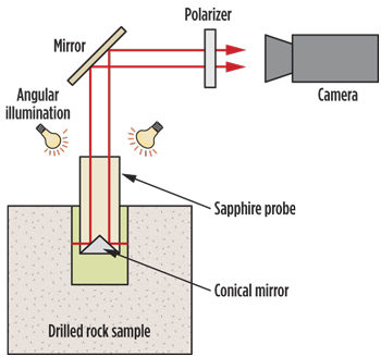
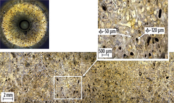
Rotary sidewall coring. Schlumberger has introduced a large-diameter rotary sidewall-coring service capable of obtaining up to 50 cores of 1.5 in. × 3 in. in a single tool run. The tool is rated to maximum temperature and pressure of 25,000 psi and 350°F, respectively.23 Baker Hughes introduced a large-diameter system in 2011,24 and Halliburton is also developing a large-diameter rotary coring tool.25 As discussed previously (see 2011 article), analyses of larger-diameter cores provide more representative reservoir data, which are essential in heterogeneous reservoirs, such as carbonates and shales. Freezing core. Freezing core at the surface is an established technique used to successfully retrieve and preserve core drilled in unconsolidated and fractured formations.26 Researchers at the Maharashtra Institute of Technology (India) are investigating the potential for in-situ freezing of sidewall cores. The results of laboratory and theoretical studies suggest that in-situ freezing will significantly improve core analysis and determination of petrophysical properties.27 SCAL core analysis. Some of the pitfalls that can occur in the laboratory during special core analysis (SCAL) were highlighted in a paper presented at the 2011 SCA conference to promote awareness in users of these data. The major points include 1) the need to understand the behavior of the laboratory equipment and fluids used in addition to the rock samples; 2) investigating the causes of unexpected results and making the necessary corrections; 3) documenting and communicating experimental failures; and 4) improving the chances for a successful experiment by estimating expected results prior to conducting the lab work.28 Low-permeability core analysis. Core analysis results for low-permeability rocks (tight sandstones and shales) between different laboratories are often inconsistent, due to variations in the standard measurement techniques and their implementation. Inconsistent determinations of permeability, in particular, can adversely impact play evaluation and development. ExxonMobil has spearheaded efforts to develop a workflow to “normalize” datasets from different vendors through corrections based on reported volumes of gas-filled porosity, water saturation and clay-bound water. It has also proposed a new steady-state technique for measuring permeability on intact rock samples under in-situ conditions. The objective of the new technique is to establish a more reliable standard for measuring permeability in tight sandstones and shales that can be used to calibrate permeability measurement apparatus, and enable delivery of consistent results across different laboratories conducting measurements on intact tight-rock samples.29,30 Rock elastic properties. Ultrasonic laboratory devices used for determining rock elastic properties, e.g., Young’s modulus, typically operate at frequencies that are much higher than those used in exploration seismology. Consequently, the results cannot be directly extrapolated for seismic-data interpretation. Curtin University has developed and is testing a new low-frequency apparatus that uses a stress-strain technique to measure Young’s modulus at confining pressures from 0 to 70 MPa.31 Dielectric rock properties. Schlumberger is currently developing a specialized apparatus to measure wideband dielectric permittivity on geological samples (see 2010 article). This equipment is designed to facilitate comparison with dielectric data obtained by other physical means, in this case the latest dielectric generation logging tool. The coaxial probe design also enables characterization of vertical porosity heterogeneity in carbonates and complex lithologies.32 Rock and core imaging techniques. A variety of SEM and X-ray imaging methods used in combination with digital analysis provide faster, less-expensive and more quantitative methods for obtaining lithology, mineralogy, grains size, and rock and fluid-flow properties on core and drilling cuttings, especially in low-permeability rocks, than conventional core analysis methods and traditional optical petrographic analysis, based on thin-sections. Digital core analysis. Petrographic image analysis (PIA) of digital core photos allows direct measurement of rock properties from these images (see 2006 article).32 Software tools available from several commercial sources allow a computer to function as a virtual microscope capable of high-resolution petrographic (thin-section) analysis and inspection, and analysis of core plugs and drill cuttings for determination of rock properties, including grain size, texture and composition.34,35 Schlumberger has developed a laboratory prototype microscopic imaging device that provides simple and reliable high-resolution core imaging in the visible light range.36 Application of conventional PIA techniques to the images obtained with the Micro Grain Imager allows estimation of porosity and characterization of rock composition and texture (pore size and distribution); use of video mode allows study of fluid mobility on the pore scale. The instrument is capable of determining localized permeability values within reasonable accuracy. Precision milling is used to drill a hole in conventional core (similar to a core plug), and a sapphire optical probe with an integrated conical mirror is inserted into the hole. The optical probe has a diameter very close to that of drill bit, enabling the optical surface of the probe to be held close enough to the formation in the drilled hole to allow effective optical images. The probe illuminates the freshly exposed surface and records a digital image with about a 10-µm resolution, Fig. 3a. The conical mirror provides a 360° view of several centimeters of the sidewall of the cored hole and the probe obtains images at several depth levels within the cored hole, Fig. 3b. In a post-processing step, the image is unwrapped, distortion induced by the mirror is removed, and the individual raw images taken at different depth levels are combined to create a single image, Fig. 3b. Combining the pore size information derived from the images with an effective-medium approximation allows rapid estimation of absolute permeability in carbonate rocks.37
SEM/EDX (scanning electron microscope energy-dispersive X-ray) identifies minerals at the micrometer scale-based on chemical composition. The instrument provides a colored mineral map that reveals the modal mineralogy and the rock texture, and can also be used to identify the grey levels in micro-CT datasets.38 FIB/SEM (focused ion beam scanning electron microscope) combines the precise cutting capability of a focused ion beam with SEM high resolution to enable highly detailed 3D reconstructions of core and rock samples with nanometer resolution.38 The focused ion beam can remove a controlled amount of material to create multiple parallel (10-nm spacing) and aligned 2D sections with 1-nm resolution. These 2D images are combined to produce a high-resolution tomographic image.38 X-ray CT. Initially developed for medical applications, X-ray CT has been used in core characterization and analysis for over 25 years.40-42 This imaging technique offers a nondestructive method for evaluating core and rock samples (for pore-space characterization) under both surface and in-situ reservoir temperature and pressure conditions. It is also used for fluid-flow visualization and quantification. In core characterization, it provides qualitative information on heterogeneity, lithologic changes, fractures, vugs, and mud invasion damage. Image resolution is a function of the frequency of the focused X-rays, from nanometer scale, to microns, and centimeters. Table 1 summarizes the measurement-scale X-ray CT systems and lists some applications.
Micro X-ray CT is an integral part of the new discipline of digital rock physics (see 2006 article), which combines the imaging data with sophisticated and computationally intensive filtering and segmentation processing methods to produce 3D representations of pore space and fluid distribution in porous media. Measurements of rock and fluid transport properties, derived from X-ray CT-generated 3D digital porous rock samples, provide good approximations to similar measurements obtained by conventional methods when modeling rock properties controlled by large pores.43,44 However, discrepancies and inconsistencies between digital- and laboratory-derived measurements may occur in rocks dominated by very small pores due, in part, to insufficient resolution of the CT images.44 Recent developments include the introduction of ultrahigh-resolution nano-CT imaging systems with resolutions of tens of nanometers that can provide insight into the microstructure, i.e., pore-scale characterization, of very fine-grained rocks, including quantification of shale porosity. Micro- and nano-CT and digital rock physics are particularly valuable in low-permeability rocks, such as shale,45 tight sandstones46,47 and carbonates,48,49 because they provide a relatively rapid method for estimating rock and fluid-flow properties compared to conventional physical measurements, which are slow and very expensive. Dual-energy CT, widely used in the medical industry, e.g., DEXA systems for measuring bone mineral density, can be used to provide radiographs and tomographic images of geologic materials and offers a quick, easy way to calibrate density and photoelectric logs. In dual-energy CT-scanning, the object is scanned twice at the same location, using a high- and a low-energy setting, which takes advantage of both the benefits of photoelectric absorption (<100 kV) and Compton scattering (bulk density)(> 100 kV).50,51 LITERATURE CITED
|
||||||||||||||||||||||||||||||
- Coiled tubing drilling’s role in the energy transition (March 2024)
- Using data to create new completion efficiencies (February 2024)
- Digital tool kit enhances real-time decision-making to improve drilling efficiency and performance (February 2024)
- E&P outside the U.S. maintains a disciplined pace (February 2024)
- Prices and governmental policies combine to stymie Canadian upstream growth (February 2024)
- U.S. operators reduce activity as crude prices plunge (February 2024)

