Electromagnetic MWD improves drilling performance in the Fayetteville
The use of real-time MWD data and reliable directional control resulted in increased average ROP and reduced drilling time.
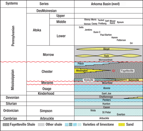
The use of real-time MWD data and reliable directional control resulted in increased average ROP and reduced drilling time.Sandeep Janwadkar and Christian Klotz, Baker Hughes; Bart Welch and Shane Finegan, XTO Energy The Fayetteville Shale, located in the Arkoma Basin of Arkansas, is one of the fastest-growing shale gas plays in North America. Horizontal drilling coupled with hydraulic fracturing makes this reservoir highly prolific, with production rates comparable to those of the Barnett Shale. However, the area presents numerous challenges including loss of circulation, wellbore instability and significant connection times, which reduce efficiency while drilling the curve and lateral sections. To address these challenges, a detailed engineering analysis was performed using a proven drilling optimization procedure. As a result of the study, engineers determined that surface pressure limitations with high rates of penetration (ROP), together with pumping of lost-circulation material (LCM) to control fluid losses, negatively affected the performance of downhole measurement-while-drilling (MWD) equipment. Standard mud-pulse MWD technology could not operate efficiently while drilling with lost circulation, no fluid returns or high LCM concentrations, and wired-pipe technology is typically cost-prohibitive in this type of application. An electromagnetic (EM) MWD system was used to transmit real-time data via EM signals through the formation instead of fluid pressure pulses through the inner bore of the drill pipe. The system provided accurate real-time MWD data and reliable directional control and was not hindered by the presence of multiphase fluids, high-density solids or LCM in the wellbore. GEOLOGICAL CHALLENGES The Fayetteville Shale gas play in the Arkoma Basin is present over much of the subsurface in north-central Arkansas. The shale’s production has been established in 10 counties, covering an area of about 2,400 sq mi. Cumulative gas production in the play has reached 640 Bcf, and average daily gas production is in excess of 1,390 MMcfd as of July 2009. About 1,700 wells are currently producing from the Fayetteville Shale, the vast majority of which are horizontal wells.1 Production depths in the Fayetteville range from 1,200 ft TVD in the northern part of the play to about 8,000 ft TVD in the south, and thicknesses range from about 600 ft in the north to 50 ft in the south. The late Mississippian-aged Fayetteville Shale is approximately age equivalent to the Barnett Shale in the Fort Worth Basin of north-central Texas. Both the Arkoma and Fort Worth Basins are foreland basins that formed in response to continental collision along the Ouachita fold belt during the Paleozoic era. A typical stratigraphic column of the eastern Arkoma Basin is depicted in Fig. 1.
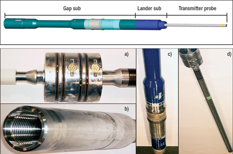
The Fayetteville Shale is black marine shale with interbedded limestone that was deposited on a southward-deepening muddy shelf. To the west, the Fayetteville is conformably overlain by the Pitkin limestone. Eastward, the Pitkin limestone grades into shale and is known as the upper Fayetteville Shale. The productive zone throughout the play, the lower Fayetteville Shale, is characterized as an organic-rich facies with interbedded black shale, pyritic shale and minor siltstone. The zone rests conformably on the Hindsville limestone, which grades into the Batesville sandstone toward the east. Where the Hindsville and Batesville are absent, the Fayetteville rests unconformably on the Moorefield Shale.2,3 In the past, drilling optimization has resulted in significant improvements in drilling performance in several other fields.4-6 Based on this experience, a team consisting of personnel from the operator and the service company outlined concerns that the operator faced drilling wells in a Fayetteville Shale field. These discussions paved the way for field visits, and an intensive effort captured the current best practices for drilling by analyzing drilling data, visiting rigs to interview personnel, and observing drilling operations. This allowed engineers to understand the problems and highlight the major issues and ultimately to establish objectives of the drilling optimization project. WELL PLAN A typical well plan starts with a 16-in. conductor pipe that is usually set at a depth of 50 to 100 ft. The 12¼-in. surface hole is drilled with mist or air to 500–600 ft, and subsequently the 9⅝-in. casing is run and cemented. The 8¾-in. vertical interval is drilled until the Morrowan Shale, at which point the hole is then displaced to oil-based mud (OBM). The 8¾-in. curve interval is usually drilled with a 10°/100-ft buildup rate. The 8¾-in. lateral interval is drilled through the lower Fayetteville Shale and usually extends the borehole 2,500–4,500 ft. A few wells with lateral interval lengths of 5,500–6,100 ft. have also been drilled. The kickoff point and TVD of the lateral intervals depend on the TVD and thickness of the Fayetteville Shale, which range from 1,200 ft TVD and 600 ft thick, respectively, in the north, to 8,000 ft and 50 ft thick, respectively, in the south. Pilot holes are drilled on some of the wells through the lower Fayetteville Shale, Moorfield and Boone Formations. After logging the pilot hole, a whipstock and cement plug are set before kicking off the curve interval. DRILLING OPTIMIZATION Discussions held at the operator’s office and rigsite along with observations during field visits were essential in establishing the objectives of the drilling optimization project. High ROP in the curve and lateral required optimum flowrates to ensure good hole cleaning. Due to surface pressure limitations on some rigs, it was necessary to minimize pressure drop across downhole BHA components. Higher ROP significantly increased the rate of cuttings generation. To minimize the setting of cuttings (cutting slippage), it was critical that survey time and connection time be reduced. Drilling with roller cone bits resulted in low ROP in the curve and lateral. Controlling the tool face while drilling with PDC bits was a challenge. Efficient hole cleaning and lost circulation control necessitated pumping sweeps with high concentrations of LCM. Sweeps loaded with LCM affected the performance of the downhole MWD equipment. Existing standard mud-pulse technology could not operate efficiently while drilling with lost circulation, no fluid returns or high LCM concentrations. Wired-pipe technology was considered cost-prohibitive in this application. Thus, the ability to pump LCM without affecting the performance of downhole MWD tools was another challenge. In the past, the operational procedure to control losses called for the directional drilling assembly to be pulled out of hole and an open-ended drill pipe run to pump LCM. After lost circulation was controlled, the open-ended drill pipe was tripped out of hole and the directional drilling assembly was run back in hole to resume drilling operations as per the well plan. This procedure resulted in nonproductive time and reduced drilling efficiency. Minimizing survey time was another challenge. With pulsed MWD systems, acquisition and transmission of surveys would be conducted before or immediately after making connections. This process added to nonproductive time, as personnel had to wait for confirmation and evaluation of MWD data before resuming drilling. Thus, reducing this time would significantly improve overall drilling performance. ELECTROMAGNETIC MWD To overcome the drilling challenges in this case, the operator and the service company decided to deploy a new EM MWD system. Compared to MWD platforms based on mud-pulse telemetry that contain moving parts in the wellbore and usually require fluid circulation to power the BHA, the EM MWD system has virtually no LCM limitation and continuous surveying capability, if using battery power. The system selected for these wells is a recent technology extension that incorporates lessons learned from previous decades of field experience of downhole-to-surface signal transmission systems. Based on proven and reliable MWD components (directional sensor sub, vibration stick-slip and gamma-ray module), the developed EM telemetry module acts as a drop-in telemetry replacement for the mud-pulse telemetry unit. As with any MWD system, the telemetry package comprises downhole and surface components. Downhole, the EM technology that was used contains three major assemblies, Fig. 2. First, the gap sub electrically isolates two poles required for generating a dipole antenna that emits the EM waves into the formation. Second, the lander sub consists of a housing sub and a pressure centralizer. The pressure centralizer contains the bore and annulus pressure sensors. The lower end of the pressure centralizer connects to the probe string. The pressure centralizer is seated in the lander sub housing, and the entire probe is hung from this point.
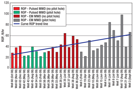
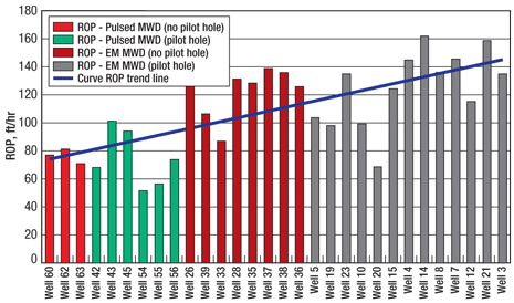
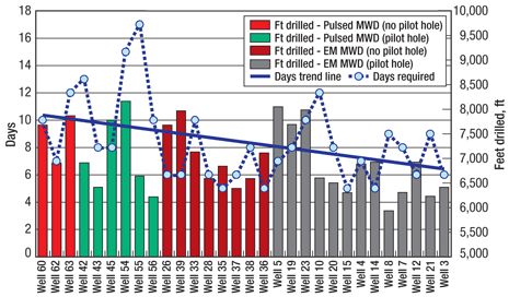
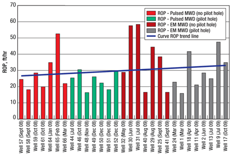
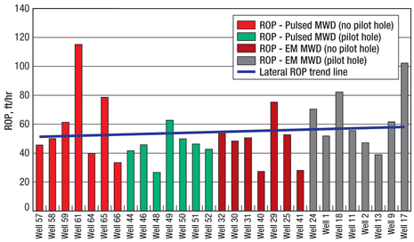
Lastly, the transmitter probe unit contains the electrical subsystems of transmitter electronics for the actual data transmission to surface, pressure electronics for bore and annular pressure measurements (for early detection of downhole drilling problems), and a memory module for high-resolution data recording. Lithium battery packs are used to power this downhole system. Additional MWD tools can be connected to the probe in order to perform detailed formation evaluation operations. The surface receiver unit of the EM MWD system is certified according to the stringent ATEX Zone 1 (EuroNorm) directive, making the system very safe. In the absence of this safety standard, it is possible that, in the event of internal damage of the surface receiver unit, electrical input ports could become electrical output ports. If this happens, electrical energy from the non-hazard area can reach the hazard area and potentially create a spark in an explosive atmosphere. By adhering to the ATEX directive, the EM MWD system described here significantly improves the safety of all people involved in the operations and eliminates the risk of a potential hazard. A critical feature of every sophisticated MWD telemetry technology is the ability to adapt to changes in the telemetry transmission channel. In the case of EM MWD, this channel is the stacked layers of formations from downhole to surface, the mud, casing and drill pipe. With the EM MWD system discussed here, it is possible to adjust downhole transmission settings while drilling the well. Numerous transmission frequencies and modulation schemes are selectable for optimal signal transmission. Because EM signal strength at surface depends on various well and formation parameters, it is important to run simulations for selection of downhole signal frequencies and output power. This process is of particular importance when planning to drill in formations, or combinations thereof, that have not been drilled with EM MWD technology before.8 In this case, the simulation results indicate whether the EM energy from the downhole tool is sufficient to overcome attenuations caused by formations known to cause a significant drop in signal strength. Depending on signal attenuation, the EM MWD system can transmit downhole measurements at data rates up to 12 bits per second, matching or exceeding telemetry speeds of existing mud-pulse system to provide high-quality measurements even under high ROPs. Since its testing phase in 2003, the EM MWD system has operated in more than 700 runs, accumulated more than 30,000 operating hours (time platform was powered up and transmitting downhole information), and drilled more than 1 million ft. During this period, the technology was successfully deployed in a large variety of applications and formations, including a deep well of more than 14,000-ft MD and environments with high gas-to-liquid ratios. The EM MWD platform has performed well in all these cases. CASE STUDIES To quantify the improvements in drilling performance, several wells drilled with EM MWD and pulsed MWD were analyzed. In this study, 66 wells drilled in a Fayetteville Shale field from May 2008 to October 2009 were analyzed. Pulsed MWD tools were used for drilling 25 wells, and EM MWD systems were used for drilling 41 wells. A further classification of these wells is as follows: Pulsed MWD: EM MWD: The entire field can be grouped into two major areas: northeast (NE) and southwest (SW). The NE area is less complicated to drill than the SW area. Wellbore instability and sloughing formation is a major concern in the SW area. Case Study 1: Northeast area. A group of 30 wells located in the NE area were considered for analysis in Case Study 1. The 30 wells are classified as follows: Pulsed MWD: EM MWD: The average ROP in the curve and lateral sections of these 30 wells is depicted in Figs. 3 and 4, respectively. The wells drilled with EM MWD show a significant increase in the average ROP for the curve as well as the lateral intervals when compared to the wells drilled with pulsed MWD. Figure 5 shows the footage and drilling time on each of these 30 wells. The footage includes the feet drilled with directional drilling tools. The number of days required (shown in blue dashed line in Fig. 5) is the time that the directional drilling tools were in hole for this group of 30 wells. The number of days required with EM MWD were significantly less than the number of days required with pulsed MWD as seen from the trend line (blue solid line) in Fig. 5. The wells drilled with EM MWD had higher average feet drilled per day than those drilled with pulsed MWD, as follows: Pulsed MWD: EM MWD:
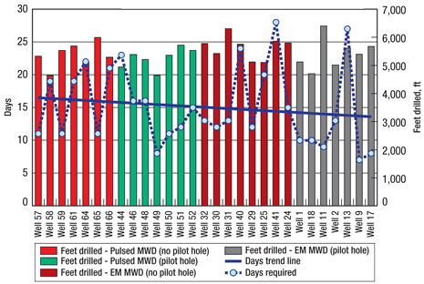
Case Study 2: Southwest area. A group of 29 wells located in the SW area were considered for analysis in Case Study 2. The 29 wells are classified as follows: Pulsed MWD: EM MWD: The average ROP in the curve and lateral sections of these 29 wells is depicted in Figs. 6 and 7, respectively. The wells drilled with EM MWD show a significant increase in the average ROP for both the curve and the lateral intervals when compared to the wells drilled with pulsed MWD. Figure 8 shows the footage and days on each of these 29 wells. The footage includes the feet drilled with directional drilling tools. The number of days required (shown in blue dashed line in Fig. 8) is the time that the directional drilling tools were in hole for this group of 29 wells. The time required with EM MWD was significantly less than required with pulsed MWD, as seen from the trend line (blue solid line) in Fig. 8. The wells drilled with EM MWD had higher average feet drilled per day than the pulsed MWD, as follows: Pulsed MWD: EM MWD:
RESULTS Deploying the described EM MWD system successfully addressed the project challenges and thus significantly improved overall drilling performance. Significant reduction in standpipe pressure was observed when using EM MWD as compared to pulsed MWD. This enabled operations under higher flowrates for better hole cleaning, improved drilling efficiency and minimized chances of stuck pipe. Survey information was available throughout connection time, resulting in overall faster connections for improved drilling efficiency. Quicker connections resulted in minimizing the time that pumps were off, thereby keeping the cuttings in suspension and avoiding hole packoff. LCM could be pumped with the EM MWD tool in hole. This eliminated a trip and improved drilling efficiency. Previously, with pulsed MWD, one additional trip was required to run in hole with open-ended drill pipe to enable pumping of LCM. Usually, controlling the toolface with PDC bits is more difficult than doing so with roller-cone bits. The EM MWD system used in these applications is capable of transmitting downhole information at higher rates than is possible with standard mud-pulse MWD technology. This feature, and the fact that the tool is powered by batteries, provide faster toolface readings even during times of flow-off. This reduces nonproductive time during connections and corrections. Additionally, PDC bits have resulted in significantly higher ROPs than were achieved using roller-cone bits. CONCLUSIONS The objectives set forth for drilling optimization were successfully achieved. Using EM MWD resulted in a 33–36% increase in the average ROP and a 13% reduction in drilling time to reach target depths. The geological complexities in this area had posed drilling challenges in the past. Due to significant improvements achieved from drilling optimization, the operator has been able to substantially increase the number of wells drilled per year.
ACKNOWLEDGMENTS This article was prepared in part from IADC/SPE 128905 presented at IADC/SPE Drilling Conference and Exhibition held in New Orleans, Feb. 2–4, 2010. The authors would like to thank the management of XTO Energy Corp. and Baker Hughes Inc. for permission to publish the data. Special thanks go to Michael Howell and Pepe Nelson for their valuable contribution in operations and in making this project successful, Sean Ragan for drafting the geological maps, Stacy Goodenough for helping to compile production data, and Jennifer Weathers and Juanita Pollock for their valuable help in gathering and compiling the drilling data. Finally, the authors would like to thank Jochen Schnitger, Todd Gooding and Oliver Backhaus, all with Baker Hughes, for providing critical feedback. LITERATURE CITED 1 Arkansas Oil and Gas Commission website; http://www.aogc.state.ar.us/Fayprodinfo.htm.
|
|||||||||||||||||||||||||||||||||||||||||||
- Coiled tubing drilling’s role in the energy transition (March 2024)
- Shale technology: Bayesian variable pressure decline-curve analysis for shale gas wells (March 2024)
- Using data to create new completion efficiencies (February 2024)
- Digital tool kit enhances real-time decision-making to improve drilling efficiency and performance (February 2024)
- E&P outside the U.S. maintains a disciplined pace (February 2024)
- Prices and governmental policies combine to stymie Canadian upstream growth (February 2024)

