ARTIFICIAL LIFT
What’s new in artificial lift
Part 1— Here are the newest developments in five artificial lift categories: sucker rod pumping; progressing-cavity pumping; gas lift; gas-well deliquefying; and jet pumping.
James F. Lea, Mewbourne School of Petroleum and Geological Engineering, Oklahoma University; Herald W. Winkler, Texas Tech University; and Robert E. Snyder, Consultant
Described here are 13 downhole and surface equipment developments from 11 companies. Part 2, coming in May, will present electrical submersible pumping (ESP) and other artificial lift innovations.
Sucker rod pumping, in many cases, evolved from classic beam pumps to include tower type units. It is the most widely used artificial lift, usually using vertical rod motions, but now also with cable, to operate a downhole reciprocating pump. PCP systems are based on a surface drive rotating a rod string, which drives a downhole pump rotor operating within an elastomeric stator. Gas well deliquefying removes liquid covering the producing formation to increase gas production. Jet pumping uses the velocity of injected power fluid to reduce pressure in a downhole jet, causing inflow of produced fluid, and lift to surface. Gas lift uses downhole valves to inject annulus gas into the tubing under liquid columns, or under optional plungers, to reduce column density and drive liquids to surface.
SUCKER ROD PUMPING
Seven new systems applied in producing wells, or in field testing, are described.
Linear-motor surface unit. International distributor and US patent licensee LIMA USA, is offering broader application of the LIMA linear motor to increase oil pumping efficiency with a tower-mounted, long-stroke system. Based in Springfield, Illinois, the supplier has been successful in applying the method and has seen increasing demand in China. Increased efficiency in artificial lift technology has long been a major goal of the oil-pumping industry. As a result, several structural evolutions have emerged, with the most efficient types incorporating a tower structure instead of a conventional beam. One thing that has not changed, however, is the power source. The rotary motor continues to be the workhorse providing the power for virtually all artificial lift technology. Described here is a new concept.
LIMA incorporates linear motor technology inside the tower structure of a long-stroke beam pumping surface unit, Fig. 1. The linear concept enables the tower to provide two functions: a longer, more even stroke, and housing the linear power source.
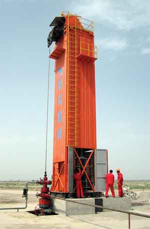 |
Fig. 1. Linear motor operates inside the tower structure to offer long, positive-controlled pump strokes for the deepest wells. Photo from Donghe, China, installation.
|
|
Although linear technology has been available for almost a century, prior application attempts were unsuccessful due to poor efficiency. The linear motor is simply a rotary motor cut open and laid out flat. Government R&D has probably done the most to modernize the concept. In its current, most common use, it has the ability to provide controlled acceleration. This has been very successful in carrier aircraft launching; and battleships are now using this type of propulsion for their long-range guns.
The new use developed for oil pumping takes this concept further by refining it with double-sided magnetic fields and a long track. The magnetic fields are electronically controlled.
The linear motor used in the oilfield pump has been designed to provide several needed functions. It offers controlled, uniform acceleration at the stroke beginning and end, and a longer period of constant speed for a longer, smoother stroke. Further, individual components of a stroke, i.e., length, up-speed and down-speed, are easily adjusted/maintained with a Siemens electronic controller. And, the unit can be monitored remotely over a cellular network.
Benefits of LIMA include: low energy use per barrel lifted; significantly improved oil output with longer strokes; good performance in deep wells—even operating below 12,000 ft; and the improved stroke characteristics means significant stress reduction on down-pipe components, resulting in far less wear and, thus, less-frequent maintenance.
The LIMA pump was created in China more than five years ago and has been tested, operated and approved by SINOPEC. Some 50 units are now operating in China, and a new factory is under construction in Wu Han, to meet anticipated demand.
Continuous Pump to Surface. Some six years ago, SOS Oiltools (now Weatherford-BMW), Lloydminster, Alberta, Canada, announced an innovative breakthrough in an alternative pumping method. The Continuous Pump to Surface System (CPTS)* is a rodless production system that performs well in diverse applications. It is designed as an alternative when conventional production systems fail under adverse conditions. The oversized and modified pump-to-surface pump is anchored downhole (Fig. 2), and production is achieved by reciprocating the entire tubing string via a hydraulic stroking unit (VSH Hydraulic Unit). This approach is specifically designed to maximize production and minimize downtime.
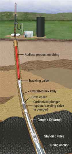 |
Fig. 2. Downhole features of the continuous pump system, without sucker rods, anchored downhole and reciprocating the entire tubing string..
|
|
|
The design has recently been modified, evolving into patented flushable technologies, called The Total Flush System, which is available only within the CPTS production system. As the only flushable pump-to-surface pump in the industry, it has the ability to flush the entire work string with the turn of a surface lever, then resume production.
In March 2006, Weatherford acquired SOS Oiltools and added the CPTS technology to its product line. The acquisition has facilitated CPTS system utilization in numerous applications in several countries.
CPTS applications include: heavy oil (thick or sand slugging); high sand cuts or slugs; dewatering gas wells; high volumes at low stroke rates; thermal applications; coalbed methane; initial sand cleanouts; and heavy oil (poor rod fall).
Sucker rod pump for heavy sand conditions. Harbison-Fischer, Fort Worth, Texas, has developed and field-tested its new, patent-pending Sand-Pro* sucker rod pump. It has been successfully tested in some of California’s toughest sand production conditions and has out-lasted previous pumps.
The new pump uses a unique method of separating produced sand from the pressure-sealing, leading edge of the sprayed-metal plunger. By keeping these hard sand particles separated from the plunger/barrel interface, the surface of the plunger and barrel can maintain the seal pressure longer, thus improving downhole run times.
The pump uses two plungers connected in tandem to separate the upper-stage, sand-handling plunger from the lower-stage, pressure-sealing plunger. The upper, soft-packed plunger has no pressure across it to force sand into it, thus reducing wear on the soft packing. And the lower, metal-sprayed plunger has no sand at its leading edge to wear it out. This gives the new design the best of both worlds for each plunger’s function.
The new pump is available in all standard configurations of sucker rod pumps that are compatible with soft-packed plungers, and can be equipped with corrosion-resistant components.
Natural energy power source system. Deluge, Inc., Phoenix, Arizona, has patented and field tested its Deluge Artificial Lift system (DAL), a low-cost, low-maintenance, highly effective method of extracting crude oil and gas from both horizontal and vertical wells. Based on the company’s hydraulic motive force Natural Energy Engine* technology, DAL is a variable-speed, reciprocating rod string system that exploits a temperature difference via a CO2 working fluid to create and deliver mechanical energy in linear or rotating motion (see World Oil, Nov. 2004 and 2005). The working temperature range of the device is 80–180°F. This allows readily available waste heat at 185°F to provide the hot input, and shallower well water at 68°F to source the cold side of the system. One-half gallon of liquid CO2 is held at 1,500 psi, as a working-fluid reservoir. Already patented in 40 countries, this unique technology requires little or no external power, and can be configured to emit zero pollution.
Deluge has successfully completed beta testing on nine shallow formation wells in the Midwest—reliably running nine DAL Model 1224 engines 24/7 for over one year, Fig. 3. The system is now available for customer placement. BP and Weatherford have shown interest in the novel engine as a solution for low-cost deliquefying of deep gas wells. The developer is designing a product line for the oil/gas industry that includes water injection pumps for flood pressurization, and products for stripper well production, gas well deliquefying and gas compression.
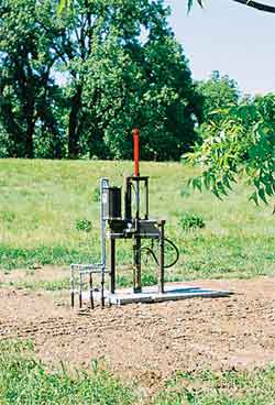 |
Fig. 3. Natural Energy Engine* rod string lift system pumping oil in Kansas.
|
|
Low volume pumping system. CDI Energy Services of Tyler, Texas, has a new artificial lift system, which operates on solar power, Fig. 4. The Low Volume Pumping System (LVPS) helps deal with fluid that impedes gas production in situations where pumping is measured in gallons per day, rather than barrels per day. A bank of batteries and a charging system are incorporated to power the system on severely overcast days and at night. A controller allows for multiple run cycles throughout a 24-hr day, to match system design with well production. The continuous fiberglass rod string is spooled into the well from a trailer instead of running rods from a conventional workover rig.
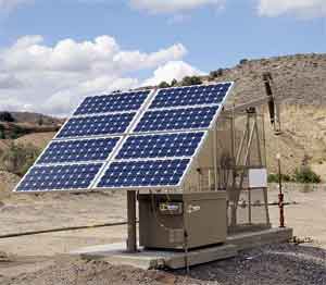 |
Fig. 4. Low-volume sucker rod pumping system can operate on solar power, with intermittent battery support, or hybrid systems using low-hp motors where electricity is available.
|
|
While most installations to date have been solar powered, the most recent applications have been hybrid systems, which include 230V grid-based electricity. Using a 1/3-hp motor with the hybrid units allows for a significant reduction in energy consumption. Whether purely solar powered or hybrid, these low-volume systems are capable of producing up to 10 bpd, using a conventional sucker rod pump.
Pump-off control with telemetry/dynamometer card capability. The Penny Pincher pump-off control has been manufactured since 1995 by the D-Jax Corporation, Midland Texas. Several improvements, such as fiber optic technology, have been applied to the system during that time. While the control has built a reputation for being low cost, simple and reliable, its application has been limited due to the lack of a load-cell option.
By the time of this publication, the developer will have available a load-cell-based, telemetry-ready Penny Pincher pump off control. The D-Jax Penny Pincher 2 retains its patented time-differential-based, pump-off-control algorithm, while offering pumping system loads through a portable computer interface.
As shown in Fig. 5, field personnel are able to change operating parameters and options, view run-time data, check current status, and retrieve surface and downhole dynamometer cards through the portable computer interface. And, for producers/operators that require remote monitoring and operating, the telemetry ready option is applicable to commercial radio, telemetry, hard-wire and satellite applications. In addition, the new system is Theta Enterprises, X-diag compatible.
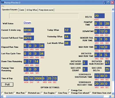 |
Fig. 5. Portable computer interface for updated pump-off control.
|
|
Improved low-cost pumping system. DynaPump, Inc., Northridge, California, has improved its DynaSave rod pumping system with an upgraded gas power unit. The pump is a self-contained pumping system designed as a low-cost option for rod pumping low-flow or low-load applications. DynaSave has a maximum, 72-in. adjustable stroke, hydraulically actuated cylinder that connects to the polish rod by means of a carrier bar and a cable system. It has a peak polish rod load of 7,000 lb; adjustable speed up to: 2, 3 and 4 spm at 5, 7.5 and 10 hp, respectively; weight slightly over 1,000 lb; and it is powered by 480V or 220V (single or triphase) electricity or the new gas motor Power Unit. Maximum flow capacity is up to 640 bpd, at depths of 500 to 700 ft, Fig. 6.
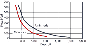 |
Fig. 6. Maximum flow capacity of low-cost rod pumping system.
|
|
The DynaSave power unit is the control center that provides ability to convert electrical energy to hydraulic power and controls pump stroke. The pumping system allows for independent speed control in both up and down direction, and allows for independent adjustment of top and bottom of the stroke. And it can adjust speed automatically to provide pump-off control.
The improvement, the Natural Gas DynaPump Power Unit, upgrades the previously applied gas engine/electric generator combination for isolated areas. The company now offers a natural gas engine power unit for directly powering the hydraulic-cylinder rod pump operation. To drive a rod pumping system with a natural gas engine has long been a staple industry operation. However, the virtual impossibility of full automation, the noise and emissions, as well as high first cost, have directed the market to convert to electricity when possible.
DynaPump has developed a power unit with full automation and communications (better than the electrical DynaPump), low noise and very low emissions (gas consumption tested at a minimum of 25% of the classic natural gas engine with a beam pump). And it eliminates 75% of the emissions due to the energy savings—for engines that run 24/7, lower emissions are extremely important. All of these benefits are available at a price slightly above the DynaPump standard electrical unit.
PROGRESSING CAVITY PUMPING
Three PCP advances from two companies include: a new control technology for progressing cavity pumps; a through-tubing conveyed PCP; and a variable speed drive for electrical submersible PCPs.
PCP control technology. Lufkin Automation, Houston, has introduced a new control technology for progressing cavity pumps using the SAM Well Manager, Fig. 7. The Lufkin SAM Progressive Cavity Pump Controller works in conjunction with a variable speed drive (VSD) to optimize fluid production, while protecting the pump. The patented control algorithm varies pump speed in steps, while measuring fluid. As long as sufficient fluid is available at the pump intake to fill the pump cavities, there is a linear relationship between fluid production and pump speed.
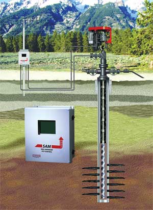 |
Fig. 7. PCP well production is controlled at an optimum rate, while protecting the pump, as the well control varies pump speed while monitoring fluid rate, and fluid over the pump.
|
|
The controller begins an operating cycle at a user-defined sampling period. It then increases pump speed by a step, and measures production rate at this new speed. It continues to ramp up pump speed in user-defined steps, measuring production at each step and establishing a speed/rate relationship. At the point that a step increase in speed does not produce the proportional increase in fluid production, the controller starts to slow the speed by steps until a production-rate reduction is measured. The algorithm continues to test the optimum production rate by repeating the speed increase/decrease sequence.
Secondary control algorithms monitor: 1) a torque signal from the variable speed drive; 2) pump shaft RPM as indicated by a Hall Effect transducer sensing a magnet mounted on the drive shaft; and 3) low/high fluid rate limits. All of these secondary control features slow the pump in the event of a violation of set limit points. If the monitored variable continues to be in an alarm condition when a programmed minimum speed is reached, the controller will stop the well to prevent pumping equipment damage.
Production measurement options supported by the controller include an accumulator for dry contact input pulses, an analog input, or the differential pressure signal from a wedge meter. Historical records of 1,500 one-min. samples are maintained for process variables including: production rate, speed output; measured pump-shaft speed; torque/power signals from the VSD; and 60-day records of daily production totals.
The controller uses Modbus-based communication protocol, and also offers the advantages of the Extended Lufkin Automation Modbus (ELAM) protocol to those SCADA software packages that go beyond conventional Modbus limitations. All configuration, status and historical data available at the local keypad are available via data telemetry link to SCADA software. The controller operates on the SAM Well Manager hardware platform, reducing spare parts and giving a single source for rod pump, injection well and PCP automation.
Through tubing conveyed ESPCP. In regions where high intervention costs are a major concern, innovative intervention methods that lower costs are increasingly important. Baker Hughes Centrilift, Claremore, Oklahoma, has developed a field-proven and cost-effective intervention method for Electrical Submersible Progressing Cavity Pumping (ESPCP) systems. The Through Tubing Conveyed ESPCP design deploys the downhole drive assembly in a production tubing string, while the pumps are accessible and retrievable through the tubing bore using wireline or coiled tubing, Fig. 8. The pump is typically the first system component to wear out in an ESPCP system. This deployment method allows the pump to be retrieved without removing the production tubing, motor, gear reducer, seal and cable, which saves on intervention costs and reduces wear on other components.
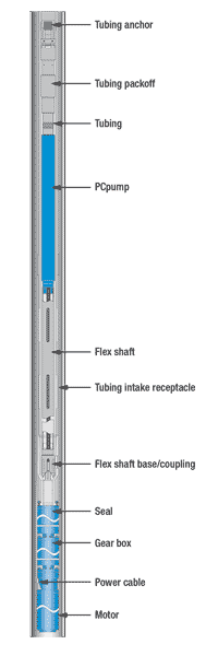 |
Fig. 8. Through tubing wireline PCP installation and removal system.
|
|
|
Centrilift installed the first through tubing conveyed (TTC) deployed ESPCP systems in Alaska, and today there are 18 systems on both 31⁄2 and 41⁄2-in. tubing in North and South America. The longest running bottomhole assembly was recently pulled after seven years, and in that time there were a total of nine pump change outs, which would have required an entire system pull using normal methods. The second longest running system is at nearly five years, with three pump changes to date. Cost savings of using a wireline rig vs. a standard rig to change out the PC pump can mean as much as $500,000 per pump pull.
The company has developed a new software incorporated into its Electrospeed 3* variable speed drives (VSDs) that minimizes: wear on the downhole system, down time and operators’ overall costs, Fig. 9. The MaxStart* software allows the Electrospeed 3* VSD to be set to normal or maximum torque start and applies an algorithm for starting a stuck, or hard-starting motor by applying forward and reverse rotation at start-up. The power conversion module of the VSD will automatically detect when the motor begins to turn, and terminate the forward/reverse direction switching to prevent motor damage.
The new software is highly effective with ESPCP systems, which typically require far more force to start than to operate. Also, internal pump friction causes PCP systems to stop back spinning, with discharge pressure remaining higher than intake pressure. Because a differential pressure will cause PCPs to rotate, the higher discharge pressure acts as a force to make starts difficult. Conversely, differential pressure acts as an aid to starting in reverse.
An ESPCP system installed in a heavy-oil field in Venezuela was consistently difficult to start, requiring attempts with very aggressive settings and reversing rotation to achieve start-up. A field service technician was required to re-start the unit after shut down from a power system. The technician would have to make set-up changes on the VSD to get the unit running and then return it to operating set points after the well stabilized. With installation of the MaxStart software, the operator could start the system remotely via a SCADA system without changing any set point; thus eliminating service calls after shut downs, for significant savings.
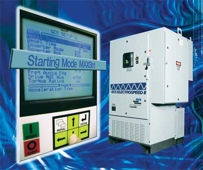 |
Fig. 9. Variable speed drive software for electrical submersible PCPs allows remote start-up.
|
|
GAS LIFT, DELIQUEFYING, JET PUMPING
Three artificial lift systems introduced by two companies include: an improved continuous gas lift chamber pump; a downhole system to reduce lower annulus flow area to increase liquid flow through the tubing; and a first-installed subsea jet pump for long offshore run time.
Continuous gas lift chamber pump. BST Lift Systems of Ventura, California, continues to improve its recently introduced Gas Chamber Pump system, which combines intermittent and continuous gas lift for high-volume production from “depleted” reservoirs normally relegated to low-production, intermittent lift. With continuous gas lift above the chamber, the intermittent cycle utilizes very low gas-lift volume to clear the chamber, Fig. 10. Results are rapid cycling, since the entire tubing to surface is not required to fill with gas to clear the slug. Compressor and production facility upsets are eliminated, making the system suitable for offshore environments with multiple completions per platform.
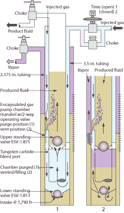 |
Fig. 10. Continuous gas pump illustrating vertical lift with the chamber purged (left), and the chamber venting to surface and filling (right).
|
|
Flowing bottom-hole pressure is minimized to surface separator pressure, plus “fluid above the pump”, plus gas gradient to surface, as the patented two-way pilot operating valve vents the chamber between injection cycles. If the fluid level is pulled down to the chamber (or chamber pump) intake, no detriment occurs as in a downhole mechanical pump. Sand and heavy oil can be lifted.
Slickline is used to change the minimal downhole components, negating costly rig time. Several tubular options exist such as side string instead of the concentric tubulars as shown. Vent and injection gas routing can be changed as per wellhead configuration. Deep wells may need upper mandrels to assist in unloading.
Rates of 1,000–1,500 bpd from a depleted reservoir with high productivity index can be expected, where a 100–300 bpd rate was a historical target with traditional intermittent lift.
Reducing critical velocity in gas well deliquefying. In gas wells with extended perforation intervals, liquid loading is a problem. The long perforation intervals and the large ID of the production casing often result in the well being incapable of producing gas rates high enough to effectively lift fluids through the tubing. Once the problem is identified, two questions arise: where to place the end of the tubing, and what type of lift is most effective.
The most common methods of artificially lifting these wells are usually one of these systems: plunger lift, soap injection, or flow-area reduction. Each of these systems has proven successful, but each has limitations. To provide a means of combining these approaches and reducing limitations, a new bottomhole assembly designed by Weatherford International, Inc., the Critical Velocity Reduction System (CVR), provides for each method to be used either independently or in combination.
The complete CVR assembly for a well within 2 3/8-in. OD tubing and 4½-in. OD casing is shown in Fig. 11. As shown, the heavy-duty flow sub has an OD of 3.063 in. and 34, ¾-in. flow ports. If needed, the upper X-Loc assembly and lower polish bore are designed to allow use of an optional isolation sleeve to shut off the flow ports. The X-Loc assembly accommodates the future installation of a plunger lift bumper spring. This heavy-duty flow sub is typically located at the top or top third of the perforated interval. The length of the 2 7/8-in. ultra-flush-joint “dead string” is directly proportionate to the well’s perforation interval.
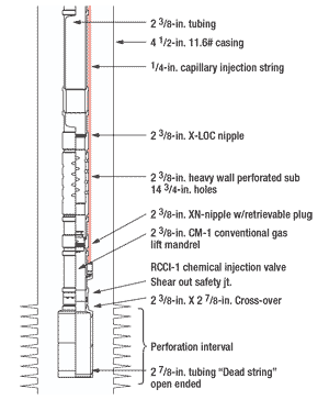 |
Fig. 11. Complete installation of enlarged lower tubing section to reduce critical velocity for gas-well deliquefication.
|
|
This completion assembly allows for the subsequent use of several liquid unloading techniques, as follows:
- Dead String (DS): With the equalizing plug landed below the heavy-duty flow sub and above the DS, flow will occur in the area between DS and casing. Flow eventually passes into the tubing through the flow sub. The DS reduces flow area in the perforation interval.
- Soap injection: With the equalizing plug above the chemical injection mandrel, soap injection into the tubing begins on a continuous basis through the external 1⁄4-in. capillary tubing, shown in Fig. 11., then exits the bottom of the DS where it is most effective.
- Plunger lift: A bumper spring can be landed in the top of the heavy-duty flow sub, and plunger lift can be established from the top or top third of the perforation interval.
For a well with 23/8-in., 4.7-ppf tubing inside 4½-in., 11.6-ppf casing and a producing wellhead pressure of 200 psi, critical velocity (from the Coleman equation), Fig. 12., to unload the tubing is 15.7 ft/sec, a flowrate of 406 Mcfd. Extending this to the 4½-in. casing with the same critical velocity applies, but the flowrate required is 1.63 MMcfd. The 2 7/8-in. DS reduces flow area inside the casing to 6.078 in.2 from 12.5683 in.2, also reducing the critical rate to 790 Mcfd.
Introducing a chemical foamer will create a further reduction in critical velocity. In keeping with the liquid unloading techniques, introduction of the foamer at the bottom of the dead string can reduce required flow up the new annulus to an estimated 327 Mcfd, from 790 Mcfd. And a reduction in required flow in the 2 3/8-in. tubing is lowered to 168 Mcfd from 406 Mcfd, Fig. 12.
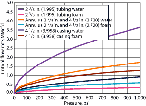 |
Fig. 12. Critical flowrates for water vs. foam.
|
|
It is recommended that the flow sub be located at the top third of the perforations, while location of the dead-string end is dictated by considerations such as: sand production, rat-hole, gas contribution to production of lower perforations, and wellbore geometry. Installation of more than 35 CVRs indicates a positive effect on production, as increases of 50 to 400 Mcfd have been realized. The same concept with a CVR assembly has also been successfully used in gas lift below a by-pass packer.
Subsea jet pump. In another artificial lift development, Weatherford has installed the first ever Subsea Jet Pump, which is operating successfully. A high-volume jet pump was selected by the operator for this application after considering other forms of artificial lift such as ESPs, gas lift and seabed booster pumps. The type of pump chosen was a reverse circulation jet pump capable of producing at rates of up to 20,000 bpd, Fig. 13.
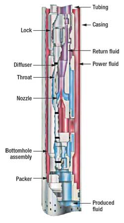 |
Fig. 13. Reverse circulation high volume jet pump.
|
|
Successful application and optimization of an artificial lift system for this field required a considerable amount of evaluation, prior to implementation, to take into consideration three prospect features, including:
- High intervention cost with the well on production
- Need for water injection for pressure maintenance
- Very limited space available on an FPSO.
The primary reason for selecting a jet pump is its proven ability to operate for extended periods of time without need for intervention. Jet pumps have a long track record for being simple and trouble free, since they have no moving parts. Reliability is excellent, and a working life of two or more years is reasonable, provided sand erosion is not a major problem.
Extended operation time was considered important due to the high cost of subea intervention. Another reason for selection was the ability to produce at rates comparable to ESPs. Its ability to use a common system for both power fluid and field water injection fluid, thus minimizing platform space requirements and surface facility complexity, was also considered a plus. WO
*Trademark property of the respective company with which it appears.
|
THE AUTHORS
|
|
James F. Lea is the Kerr McGee professor, Mewbourne School of Petroleum and Geological Engineering at Oklahoma University. He holds BS/MS degrees in ME from the University of Arkansas, and a PhD in ME from Southern Methodist University. Lea worked for Sun Oil Co. as a research engineer from 1970–1975, taught at the University of Arkansas from 1975–1978, was team leader of production optimization and artificial lift at Amoco EPTG from 1979–1999; was chairman of the PE Department of Texas Tech from 1999–2006, and recently assumed his present position at the University of Oklahoma. Lea is a registered professional engineer, and has authored several patents and many publications related to production and artificial lift. He received the SPE Production Award, has been SPE Distinguished Lecturer twice and received the Slonneger Award from the SWPSC.
|
|
|
Herald W. Winkler is former chairman, now professor emeritus and research associate, in the Department of Petroleum Engineering at Texas Tech University in Lubbock, Texas. He is presently working as a consultant in artificial lift, specializing in gas lift.
|
|
|
Robert E. Snyder, consultant, recently retired from Gulf Publishing Co. (GPC). He earned a BS degree in mechanical engineering from the University of Wyoming in 1957. Snyder served two years in the U.S. Air Force, worked 10 years for Marathon Oil Co., GPC for 29 years, and Completion Technology Co. for seven years. Within GPC, he served as engineering editor, editor of Ocean Industry and World Oil. He has co-authored several patents, authored many technical articles and made numerous technical presentations.
|
|
| |
|


