Artificial Lift
What’s new in artificial lift
Part 1 – Fifteen new systems for beam, progressing-cavity pumping and plunger lift.
James F. Lea and Herald W. Winkler, Texas Tech University, Lubbock, Texas; and Robert E. Snyder, Executive Engineering Editor
Described here are 15 recent developments in three categories of artificial lift technology, including: beam pumping (seven items); progressing-cavity pumping (PCP) (four); and plunger lift (four). Part 2, coming in the May issue, will present electrical submersible pumping (ESP) and other, miscellaneous, artificial lift-related innovations.
Beam pumping – by far the most widely used type of artificial lift – comprises a motor-driven surface system lifting sucker rods within the tubing string to operate a downhole reciprocating pump. PCP systems are based on a surface drive rotating a rod string which, in turn, drives a downhole pump rotor operating within an elastomeric stator. In plunger lift, a freely moving plunger falls through fluids in the tubing and is lifted back to surface with its slug of mostly liquids by use of formation, or injected, gas admitted from the tubing-casing annulus.
BEAM PUMPING
The seven recently applied products for improving beam/ sucker-rod pumping feature: a pump-off controller providing for custody transfer; a tubing rotator to reduce tubing wear; an improved chemical injector; an adjustable downhole valve rod/ pull-tube guide; an integrated system combining rod-pump controllers and variable speed driver; a free, updated program for designing/ predicting beam pumping performance; and a new 92+ Rc hardness coating for critical downhole equipment components.
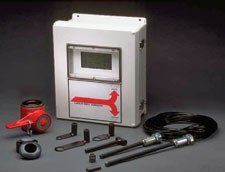 |
Fig. 1. Pump-off controller with custody transfer capability.
|
|
Pump-off control/ custody transfer. Lufkin automation will introduce custody transfer of gas in the SAM Well Manager rod pump controller in the 2nd quarter of 2005, Fig. 1. SAM has proven itself as the technology leader in beam-pump automation with its downhole pump card control and the additional I/O functions, making it a powerful remote terminal unit (RTU). This state-of-the-art system has allowed Lufkin to add American Gas Association AGA 3 and AGA 8 gas calculations from API, and meet requirements for custody transfer.
A local liquid crystal display (LCD), as well as a laptop program allows viewing and calibration of the system; plus, the unit is SCADA ready. Traditional transmitters can be used for pressure and temperature inputs, or a “smart transmitter” can be connected to the RS485 port via the Modbus Master option.
Beam pump systems have proven to be an effective and low-maintenance method to produce fluids, and have been used on CBM (coalbed methane), as well as traditional, gas wells for dewatering. POCs (pump-off controllers) have been used for years with beam pump systems to control pump fillage, but there was not a way to measure gas rates. This new system will control the well for pump off, and monitor the gas.
A POC will cycle a well on and off to match the reservoir’s fluid production rate. During the downtime, the well will build up fluid and then the well is turned back on to pump the fluid down. On a gas well, during this downtime, the buildup can cause the gas rate to fall off due to the fluid-head back pressure. SAM monitors this gas flow and will turn the beam pump back on to pump the fluid down and allow the gas to continue to flow.
The CBM or gas well, with a beam pump system, typically will have a POC and an EFM (electronic flow measurement) device at the well. This duplicates hardware and communication systems. Lufkin has incorporated both devices into the new system to: lower cost, train the operator, and lower long-term maintenance. SAM, with custody transfer, will help operators produce their wells with the standard benefits of reduced POC lifting costs, while maximizing gas rates. The continued challenge to reduce costs while maintaining production has been met with this combined new technology.
Tubing rotator. Omega Technologies Inc. in Seabrook, Texas, has introduced a couple of new innovations to reduce: 1) tubing wear; and 2) the amount of side-stream flush used in a continuous chemical injection system on choke control.
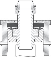 |
Fig. 2. Manually turned tubing rotator spreads tubing wear around entire pipe circumference.
|
|
The first innovation significantly reduces rod pumping repair expenses due to corrosion and wear. This patent-pending, low-cost, manual Tubing Saver Rotator (TSR) was installed in 25 wells and resulted in a 76% reduction in failure rates, yielding over 100% investment rate of returns. TSR should economically benefit wells with failures occurring more than once every 2-1/2 years.
The system replaces the conventional bowl and slips in a wrap-around wellhead with a tubing mandrel turning on thrust bearings sitting inside a bowl that is sealed with O-rings, to provide a sealed greased bearing housing, Fig. 2. The system is manually rotated about once per month with a 24- or 36-in. pipe wrench. This technique takes the wear – around 20% of the circumference – and spreads it around the entire circumference to yield five times the area to wear down before failure.
The wearing of the tubing causes tubing splits, due to metal loss, and corrosion holes, due to wear wiping off the corrosion inhibitors every pump stroke. Manual rotation allows the chemicals to protect the tubing on 80% of the circumference between rotation periods, while more expensive automatic rotation wipes off the inhibitors in about one day. Thus, the new rotator reduces “tubing splits” and “corrosion acceleration due to wear” with a simple design that fits inside most wrap-around wellheads.
 |
Fig. 3. Self-cleaning system reduces side-stream volumes for continuous chemical injection.
|
|
Improved chemical injection. Another innovation from Omega Technologies Inc. is the patent-pending Side-stream Flush Restrictor (SFR), Fig. 3, that reduces the electricity per barrel of fluid lifted and allows an increase in production, or slow-down of the pumping equipment, to reduce lifting costs. The system is self-cleaning, reducing side-stream, or slip-stream, volumes used in continuous chemical injection at the wellhead for rod-pumped, electric submersible, or progressing-cavity pumped wells, with investment rate of returns exceeding 100%. The new system should be used on all wells with continuous chemical injection, to replace conventional choke designs.
The SFR was implemented on about 800 rod-pumped wells, utilizing continuous chemical injection, and helped reduce electricity demand by 0.6 MW, and significantly reduced pumping failures. The conventional side-stream, or slip-stream, lines used for continuous chemical injection utilize a choke (1/4-in. needle valve or ball valve) that sometimes flow circulation volumes of 40 bpd to 100 bpd per well. This common design was replaced with the new design, resulting in reduced side-stream flush rates of 7 bpd to 75 bpd per well – a 750 field-wide horsepower savings – and allowed pumped-off wells to be slowed down, reducing well failures.
In wells having fluid above the pump, the system increases production by reducing side-stream rates, thus allowing the pump to produce more reservoir fluid. The system has a self-cleaning filter that sticks into the flowline to prevent the SFR line from plugging; and the filter backflows on the downstroke of the pumping unit to self-clean, or it can be back-flowed manually in other pumping arrangements. The new system uses a high-friction line, without a choke, in lieu of the conventional choke arrangement, which: 1) allows larger particles to flow through the line without plugging off the flush lines; and 2) helps prevent freezing in the line. Improving the operation of the side-stream flush line either saves electricity or results in pumping more fluids. Pumping repair frequency is reduced with a better continuous chemical injection system.
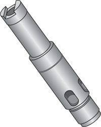 |
Fig. 4. Adjustable valve rod and pull tube guide.
|
|
Adjustable valve rod guide. The new Adjusta-Guide adjustable valve rod guide, Fig. 4, from Harbison-Fischer, is designed to simplify the adjustment to achieve the highest possible compression ratio in sucker-rod pumps.
The new adjustable valve rod and pull tube guides are designed to allow precise, controlled spacing in a rod-drawn downhole pump. In a typical pump, the spacing is based on the valve-rod or pull-tube length. This length is usually in 1-in. increments – or the rod or tube is special cut to be close to the required length needed – to allow the traveling valve on the bottom of the plunger to be spaced as close as possible to the standing valve at the bottom of the barrel. This close spacing allows for a better compression ratio that, in turn, improves the pump’s ability to work with gas present in the fluid.
The adjustable valve rod and pull tube guide allows the spacing to be adjusted up or down with greater precision, and make up for gains or losses in the pump due to manufacturing tolerances, and to keep from custom cutting and threading valve rods and pull tubes.
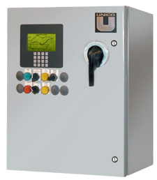 |
Fig. 5. Improved controller combining rod-pump controllers (RPCs) and variable-speed drive (VSD).
|
|
Combined rod-pump/ variable-speed-drive controller. Sucker-rod pumping systems have used various control methods to optimize production, improve energy efficiency and reduce maintenance. These systems typically use rod-pump controllers (RPCs) to cycle the pumping unit. Occasionally, variable-speed drives (VSDs) are used with RPCs to improve operation by modulating pump speed. An improved control has been developed by UNICO Inc. that combines RPC and VSD functions in an integrated system, Fig. 5.
Combining these functions enhances both system measurement and control capability. The improved control uses the VSD to exercise the pump through a complex sequence that automatically identifies motor electrical parameters, overall gear ratio, gearbox efficiency, counterbalance, rod friction, traveling/ standing valve problems and pump leakage. These parameters, combined with pumping-unit geometry, rod-string design, and pump selection, allow real-time measurement of gearbox torque, rod-load velocity/ position, pump load/ velocity/ fill, and fluid production/ level.
These measurements can be displayed as time-based or dynamometer-type plots of surface and downhole conditions on the system graphic operator interface, or remotely accessed using the controller wireless radio link or cell-phone connection. The control also offers up to one gigabyte of mass storage of measured parameters using a data sampler. The sampler can also be user programed to capture high-resolution, multi-channel information. Measured pump intake pressure and fluid flow can be compared against an internal reservoir model.
The system also protects against gearbox stress, bridle separation and rod partings by using the measured values to limit gearbox torque and minimum/ maximum rod load. Several unique pump-speed modulation techniques are incorporated for: optimization of production, control of pump fill and casing fluid level, elimination of gas interference and fluid pound, and power consumption reduction. The control can be configured to operate all pumping unit geometries, including conventional, phased crank (Mark II and Reverse Mark), air and beam balanced, linear (Rotaflex) and bent beam (HG) units.
Beam pump design program update. Newly printed in Spanish for 2005, QRod is the most widely used, free program for design and prediction of the performance of sucker-rod beam pumping installations (total downloads to date are 3,440). Echometer has released an updated version 2.1 of the program that allows displays of both input and output in either English or Spanish. The version for the PC can be used free of charge. The software can be downloaded for installation and use on any number of PCs from http://www.echometer.com/software/index.html.
The objective is to help the beam pumping system designer implement state-of-the-art design technology without getting buried with details. The program uses a wave equation solution to accurately predict surface dynamometer loads, gearbox torque and pump capacity, with a minimum amount of input. The effect of changing a parameter such as tubing anchor, stroke length, stroke rate and pump diameter can be immediately seen in the dynamically updated plots.
Available as a software option for the PC, the user can select the output and display language. Fig. 6 shows the input and output in Spanish. The output program includes pump displacement, rod-string loading, surface unit and motor size requirements for any input depth and design production rate. The QRod-Web calculator can be used free of charge via the Echometer Web page, http://www.echometer.net/QRod/.
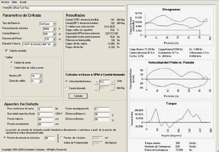 |
Fig. 6. Spanish-language program for design and prediction of sucker-rod beam pumping installations.
|
|
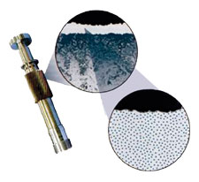 |
Fig. 7. Representation of new metallic coating shows dispersion of E-Carbon particles measuring less than 5 angstroms (0.005 microns).
|
|
Metal surface coating. As a solution to wear and corrosion, technological advancements from Eagle Innovations Inc., St. George, Utah, have now made possible the next generation of downhole pumps. Applications of the new “E”-CARBON coating, a thin, dense composite of proprietary materials, Fig. 7, onto standard pump components, have resulted in unprecedented increases in operational life.
The new surface coating, with a hardness of 92+ Rc, offers today’s oil tooling design engineers/ manufacturers the opportunity to achieve maximum performance levels with downhole pump equipment. The coating does not fracture or separate from base metals now being used. Bending impact and normal operational flexing will not cause the coating to chip or peel. It operates successfully at temperatures up to 1,400°F (775°C) with no adverse effects on either coating or base metal integrity.
Unlike with other metals, opposing or mating surfaces coated by the new process have a greatly reduced coefficient of friction. Pump components, i.e., barrels, plungers, balls and seats, which are subject to sliding and moving contact, can be coated with the new material and are much easier to assemble and disassemble – galling and fretting corrosion are essentially eliminated.
The coating is uniformly distributed over all surface areas. Deposit thickness tolerances are closely maintained and range between 0.001 in. and 0.002 in. Other benefits include:
- All standard base metal alloys can be coated
- Excellent corrosion resistance
- Becomes integral with base metal, no chipping or peeling.
Applications include: 1) ball/ seats, barrels and plungers – all base alloys; 2) valve rods and bushings; 3) threads – ID/OD; 4) gears and bearings; 5) PC pump-rotor; and 6) chokes. The developer says the system can essentially be applied to all pump components used in the oil patch.
PROGRESSING CAVITY PUMPING
Four PCP advances from three companies include: a low-horsepower drivehead; a new PCP for heavy oil; an insertable high-volume PCP; and a new variable speed drive.
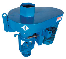 |
Fig. 8. New drivehead for progressing- cavity pump expands the LIFTEQ series, for lower horsepower requirements, and features a positive brake system without ball bearings.
|
|
Low horsepower drivehead. Baker Hughes Centrilift has expanded its drivehead series to include the LIFTEQ LT30E model for lower horsepower requirements, Fig. 8. The system is designed to effectively meet the needs of coalbed methane dewatering operations, as well as low-volume conventional oil well production.
The compact design has no externally mounted hoses, pumps, belts or other fragile components that can be damaged during installation or operation. An internalized braking system is protected from effects of outdoor exposure, enhancing durability and trouble-free/ maintenance-free backspin control. The braking system is self-regulating, with no manual adjustments required to regulate recoil speed.
The effectiveness of many traditional braking systems that include a set of ball bearings for brake engagement, are subject to varying oil viscosity, which can negatively affect brake operation. The new model uses a positive brake system that eliminates need for ball bearings and, as a result, minimizes the influence of changing oil viscosity within the drivehead. A stand-pipe design replaces bottom seal requirements, eliminating the possibility of lubricating oil leakage. A stuffing box and a rotating mechanical seal are both available to provide a seal around the polished rod.
PCP for heavy oil production. Heavy oil has been produced using progressing-cavity pumps since the late 1980s. The accumulation of field experience and incremental product developments over time have enabled engineers to continually upgrade the technology to better produce this sometimes difficult application. Contributing to this trend, Baker Hughes Centrilift has added the newly developed 110-D-2600 PCP (1.1 bbl/rpm @ 2,600 psi @ 100% efficiency) to the LIFTEQ PCP product line specifically for heavy oil production applications.
The various combinations of conditions such as high viscosity, sand production, high flow losses and low BHPs commonly associated with heavy oil production require a design that balances the impact of all these conditions. The large 3.75-in. OD tube of the 110-D-2600 provides a greater cavity cross-sectional area, which enhances viscous inflow. The internal geometry decreases fluid velocity in the stator to reduce erosive effects of sand and abrasives.
The pump geometry also provides for a larger rotor diameter, which is capable of sustaining torque-induced stresses common to this application. The shorter rotor pitch length enables both a greater pump differential pressure over a comparably short pump and more effective movement of solids through the pump.
The new pump is manufactured with Centrilift’s field-proven LT2000 elastomer. In heavy oil applications, this has operated with minimal swell, and has proven resistant to abrasives. In addition, the mechanical strength of the elastomer can provide sustained operation at high pressure.
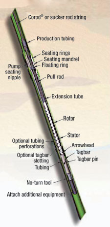 |
Fig. 9. Insertable high-volume PCP cuts running/ pulling time and reduces pump assembly length by up to two-thirds.
|
|
Insertable high-volume PCP. Weatherford took a good idea and made it even better with the Arrowhead insertable progressing-cavity pump, Fig. 9. Insertable PCPs reduce downtime during running and pulling phases by requiring removal of only the rods, rather than the tubing string also. This new patented design reduces pump assembly length by as much as one-half to two-thirds.
As a result, this PCP is capable of high lift and large volumes. Pumps with volumes of up to 5,000 bpd are available, depending on tubing size and operating conditions. Pump lifts as high as 5,250 ft have been achieved. In addition, the shorter pump configuration also simplifies shipping and handling.
The new PCP is positioned with a single-pump seating nipple and a no-turn tool that does not require a tubing interface device. This simplified arrangement eliminates need to space out tubing to accommodate specific pump lengths. As a result, different sizes of insertable pumps can be run into the same tubing string over well life without having to pull the tubing. The simplified assembly is easier to run and is more reliable than dual-attach-point systems. It is also less likely to get stuck by sand/ debris.
The enhanced tool can essentially be used in applications where a conventional PCP is used, as long as the tubing housing the insertable PCP fits inside the casing. Significant savings can be realized in reduced servicing costs by using the pump in wells where change-outs are frequent. In remote locations where a complete service rig comes at a premium cost, the new pump allows servicing by less expensive means with a flush-by or other rod-pulling device.
Weatherford recently used the new system in an application in Canada. The original pump in the horizontal oil well was pulled after nearly 17 months in use. A flush-by unit performed the workover to replace the insert pump, using the new PCP, which took about 3 hr. An operation of this type with a standard PCP takes about 8 hr. A flush-by unit usually bills at US$141/hr, compared to $266/hr for a conventional service rig, as required for change-out of a standard PCP. After the change-out, the new pump operated at 91% efficiency.
The new tool effectively enhances a pump-system workover operation with a simple, yet innovative approach. Insertable PCPs are currently applicable inside 3-1/2-, 4-1/2- and 5-1/2-in. tubing and larger, if requested. Additional installations are in place and operating in Canada, Venezuela and offshore West Africa.
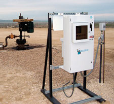 |
Fig. 10. Variable-speed drive features cost-saving benefits through digital solution combining precise torque/ speed control.
|
|
Variable speed drive. R&M Energy Systems has launched a new software product, the Guardian variable speed drive (VSD), an innovative technology advancement that offers substantial production/ cost-reduction benefits to end users, Fig. 10. The new VSD is an effective digital solution that provides versatile production control and informative monitoring of downhole PCP systems. A combination of precise torque and speed control in a single durable package is the key to maximizing production and increasing energy efficiency, while providing total protection of PCP systems to ensure equipment longevity.
The proprietary software incorporates a complete model of the total PCP system. This program provides continuous feedback of torque, speed, pump efficiency, fluid rate and estimated downhole pressure. This feedback, measured against operator set points, allows the system to provide a highly effective control method for protecting downhole equipment and maximizing production.
The Guardian VSD:
- Monitors the PCP, motor, rod speed and torque
- Offers a pump flow monitor and production accumulator
- Provides embedded data in the software for rod string, tubing, reservoir and PCP model
- Monitors and controls fluid level, and
- Provides remote monitoring by network servers.
Fluid level over the pump intake is controlled with manual speed adjustments or automatically by the system software. The new pump-off control capability maximizes well production for any given inflow characteristic, and a power optimizer reduces electric utility cost for any inflow rate.
PLUNGER LIFT
Four recently introduced advances in plunger-lift (PL) technology include: a PL controller with added capabilities; a PL analysis system that locates the plunger at all times; an enhanced plunger chamber lift; and an improved casing plunger.
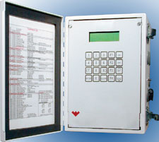 |
Fig. 11. New plunger-lift controller model extends capability of previous systems to collect additional well and production facility data.
|
|
Plunger lift controller. The latest in a line of production optimization solutions is the CEO FOUR controller from Weatherford and eProduction Solutions, Fig. 11. This new controller extends the control methods of the CEO THREE+ controller. Optimization functionality has been added that allows operators to more accurately detect well conditions to produce wells at maximum efficiency levels.
As with the earlier system, the new controller provides time, pressure, rate and differential-based control modes. The new system adds: gas-flow calculations through AGA standards, a smart interface to industry standard tank level gauges, a generic Modbus scanner to poll local EFM RTU equipment and enhanced data-logging capabilities. These new features allow the operator to monitor/ collect additional data from the well site and adjacent production facilities.
The addition of flowrate and tank-level gauge support allows the operator to optimize well production through tuning of the system for maximum efficiency. For example, the controller can poll a flow computer and store gas flow volume and rate information using the multi-channel data logger. Centralizing the information from all smart devices significantly reduces complexity and cost of well-site configurations and enables use of a single radio to retrieve all necessary well-site information.
The CEO FOUR rounds out Weatherford’s plunger lift offering in conjunction with eProduction’s production enhancement solution, to offer a range of options – from a very simplistic controller, all the way through advanced control options.
Plunger lift analysis. Echometer has developed a new, innovative Plunger Lift Analysis System that takes the guesswork out of PL analysis, troubleshooting and optimization. One of the primary requirements for the operator, to efficiently and economically operate PL installations is: “Know at all times where the plunger is!”
Otherwise, the operator, even when using electronic controllers, has to guess at the proper shut-in / afterflow time and plunger velocities. The major problem of not knowing plunger location during the operation cycle has been overcome with this new technology. The system increases efficient PL operation by allowing the operator to see the plunger throughout its cycle and maximize oil/ gas production from PL-lifted wells.
The portable system is a very sensitive acoustic/ pressure monitoring system operated through a user-friendly graphical Total Well Management software application. The portable system, comprising a laptop computer and analog/ digital converter, is programed to monitor the well during the plunger cycles, recording data at high speed from the microphone of a conventional acoustic fluid level gas gun and two pressure sensors installed on the tubing and casing head.
Shown in Fig. 12 is the acoustic signal, plus tubing/ casing pressures acquired during the shut-in time period, [B] to [C], of a cycle. With this system, the tubing collar reflections are used to determine plunger velocities; it is now possible for the operator to virtually “see” the plunger at all times during its cycle and determine precise plunger fall velocity – 200 ft/min. in gas and 39 ft/min. in liquid. Marker [3] identifies where the plunger hit liquid in tubing and how much liquid volume accumulated at the bottom of the tubing. Marker [4] identifies when the plunger reaches the bumper spring and what minimum shut-in time is required to maximize well production.
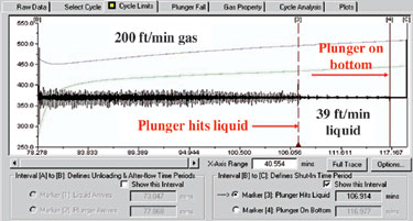 |
Fig. 12. Acquired data from pad type plunger during cycle shut-in period.
|
|
Having a detailed analysis of the well operation is a tremendous advantage that makes PL production optimization achievable, with a minimum of effort and time devoted to trial and error procedures. This advantage is equally important for timer-based as well as intelligent controllers; since, in both cases, it is necessary to make initial estimates of appropriate shut-in, plunger arrival and plunger fall times. In addition, the system’s capability of calculating volumes of liquid and gas produced during the cycle and determining the well’s potential gives invaluable information regarding operation economics and the potential for improvement.
Plunger-enhanced chamber lift. Wells with long perforated intervals and low-pressure reservoirs can often benefit from some form of chamber lift to improve production. By creating a chamber, the fluids that accumulate during the production cycle are dispersed over a larger cross-sectional area, creating less backpressure on the formation. Gas is injected into the annulus, displacing fluid into the production string; and intermittent cycles to deliver gas to the surface are repeated. Operation inefficiency over time creates excess fluid fallback, and well performance declines.
With Plunger Enhanced Chamber Lift (PECL), from Ferguson Beauregard, Tyler, Texas, a plunger is added to the chamber lift to improve efficiency and reduce liquid fallback, Fig. 13. Surface and sub-surface mechanical designs vary, and one form uses coiled tubing and standard tubing to create a concentric tubing design. By sealing off the two strings at the bottom of the well, a secondary annulus or chamber is formed, and this conduit allows for the transfer of injection gas to efficiently remove liquids from the wellbore.
 |
Fig. 13. Plunger-enhanced chamber lift, Step 4.
|
|
A typical operating process using this design would include the following steps:
- Precharge cycle
- Purge on cycle
- Purge off cycle
- On cycle, shown in Fig. 13
- Afterflow cycle, and
- Closed cycle.
Key benefits of this type of operation allows the producing system to: 1) achieve continuous flow; 2) produce long perforated intervals with low BHP; 3) reduce friction through annular flow; 4) reduce formation and compression surge; and 5) allow total gas system management.
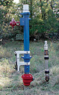 |
Fig. 14. Improved casing plunger with cup design that falls freely, then seals pneumatically during ascent and fluid lifting.
|
|
Improved casing plunger. Every producer needs a “PAL.” Innovations, recently patented, in casing plungers for 4-1/2-in. and 5-1/2-in. casing have been developed and introduced by P.A.A.L., LLC., Oklahoma City, Oklahoma, Fig. 14. These radical departures from old technology offer production increases and reduced operating expenses for lower-pressure oil and gas wells requiring artificial lift. “PAL” cups utilize an entirely new concept of shape and function. Previous available models relied on cup diameters in excess of casing ID to secure the sealing contact with the casing wall.
The innovative new cup design is smaller than the casing ID and eliminates unnecessary wear of the cups on descent. The cups are first mechanically actuated to seal against the casing wall at the well bottom. Then, through the simple, but clever, design of the system, the cups are sealed pneumatically for ascent and the unloading of accumulated wellbore fluids that inhibit, or prevent, production. A surface lubricator designed to provide simple and convenient retrieval of the system’s plunger can be configured for free fall, to catch and hold, for time release, or for release on monitored and pre-set wellhead pressures.
After five years of development, testing and actual production results, conclusive evidence verifies significant success in many areas. Production increases of five fold have occurred. Better utilization of surface equipment – through replacement of tubing plungers, rod pumps and pump jacks – has been achieved. Often, salvage value of the existing equipment exceeds the cost of installation.
In some cases, replacement of pumping equipment maintained the same production, but with substantial reductions in lease operating expenses. In other cases, wellhead operating pressures have been lowered, extending productive well life. Well depths have varied from 2,000 ft to over 8,200 ft. Multiple-weight casing strings and old squeeze cemented casing leak repair sections are easily accommodated. In addition, the presence of paraffin seems to be an advantage. Installations in all combinations of wellbore fluids, and BHPs from 60 psi to over 350 psi have been successful. 
THE AUTHORS
|
 |
James F. Lea, professor and Roy Butler Chair Holder, Texas Tech University, Lubbock, holds BS/MS degrees in ME from the University of Arkansas, and a PhD in ME from Southern Methodist University. He worked for Sun Oil Co. as a research engineer from 1970 to 1975; from 1975 to 1978, he taught engineering at the University of Arkansas; and from 1979 to 1999, he was leader of optimization and artificial lift at Amoco EPTG. He served as Chairman of Petroleum Engineering at Texas Tech from 1999 to 2004. Mr. Lea is a registered professional engineer in Texas; he has authored/ co-authored several patents, as well as publications on artificial lift.
|
 |
Herald W. Winkler is former chairman, now professor emeritus and research associate, in the Department of Petroleum Engineering at Texas Tech University in Lubbock, Texas. He is presently working as a consultant in artificial lift, specializing in gas lift.
|
| |
|
|
 Part 2 Part 2 |
|

