 |
United Kingdom |
|
Maximizing separator performance through sand removal
S. Fish and G. Brookshaw, Merpro Limited
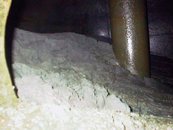 |
Fig. 1. Accumulation of sand within a production vessel.
|
|
As existing fields age and previously economically marginal fields are developed, sand production and sand management become increasingly important. Sand accumulation within process trains is one of the major factors that disrupts and limits production. Produced sand can accumulate within production vessels (Fig. 1), reducing separation volume and residence times and, therefore, separation effectiveness. To maintain separation efficiency, the flowrate through the separator must be reduced, which causes a loss or deferment of revenue. Even a modest 5% reduction in flowrate on a 20,000 bpd installation will equate to $40,000 per day lost gross revenue at $40 per barrel.
Merpro is a Montrose, Scotland-based company that specializes in the design and manufacture of sand handling equipment. The company’s proprietary TORE hydro-transportation unit is proving successful in removing solids from separators without causing production interference, and in enabling separators to operate continuously at maximum efficiency. The unit is compact with no moving parts, which, given a small fluid supply, can fluidize and transport solids over large distances and elevations.
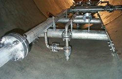 |
Fig. 2. The new manifolds within a separator vessel.
|
|
Multiple units are manifolded together within a vessel, with each manifold usually consisting of four or eight units with common shared inlet and outlet pipework, Fig. 2. Installations range from one manifold of four units, for small vessels, to multiple manifolds for larger vessels, designed to provide optimum coverage of the vessel base to maximize sand removal.
For newbuild vessels in projects where solids are expected, the new manifolds are designed as part of the initial vessel and package design, and are installed within the vessel at the outset. They are also installed as a retrofit solution in existing vessels where solids accumulation has become a problem, with existing nozzles or manways being used to accommodate the motive fluid inlet and slurry outlet pipework. Retrofit installation typically takes two days, which can be undertaken during a planned maintenance shutdown.
One case study of the new manifolds in operation is from Asia Pacific, where separator vessels on a platform were experiencing serious solids deposition. The previous practice was to shut down production for a total of four full days, every three months, to drain the vessels and dig out produced sand. This incurred significant shutdown costs, and even greater loss of production revenue.
The new manifolds were installed within the separator vessels in 2002 and, since that time, the operator has not had to shut down production for sand removal. The manifolds are operated every 12 hours removing about half a tonne of sand each time. This has saved 16 days of production per year that would otherwise have been lost, eliminating associated shutdown costs, and increasing annual revenue.
A second example of using the new manifold is in the North Sea, on a platform where the existing sparging system had been causing excessive sand in the produced water outlet, and where production had been restricted by the additional jetting water introduced into the separator. The new manifolds were installed within the production and produced water separators in March 2003. They are now removing in excess of 80 kg (175 lb) of sand every two days from each production separator, with much improved operational stability.
Since the fluidizing action of the manifolds is a localized effect, the problems with solids in the produced water outlet have been removed. In addition, because there is minimal turbulence to the liquid interface within the vessels, and the feed water and slurry discharge rates are balanced, the separator interface level remains unaltered, allowing separation of liquids to continue unaffected while solids are removed.
The greater efficiency of the operation compared with the operator’s original sparging system, means that less water is required for sand removal. A four-manifold setup requires a maximum of 16 m3/h (4,227 gal/hr) of water to operate, compared with over 100 m3/h (26,417 gal/hr) for a conventional jetting system. The lower water requirements mean that both upstream water and downstream slurry handling systems can be of smaller capacity, further reducing costs.
By using these manifolds, oil throughput has been increased and the field life, which was in the tail phase, has been extended. This is allowing wells to continue in operation that would otherwise have become unprofitable. 
|

