Successfully drilling ERD development wells by slot recovery in a depleted field utilizing MPD, offshore Malaysia
Block PM, on the east side of Peninsular Malaysia, has four fields that produce oil and gas. These fields cumulatively produce an average 10,500 bopd and flare close to 12 MMcfd of gas. The drilling and workover campaign planned for 2021/2022 involved both the WD and I fields in this block. The objective of the campaign was to perform slot recovery of two wells and sidetrack to new objectives.
One well (Well 9) is an oil producer; the other (Well 13) is a water injector. In total, 18 wells were drilled and completed during 2013 to 2015, using three different rigs from the wellhead support structure. Most of these wells have a build-and-hold profile, with TD depths between 1,100 m to 4,465 m and inclination between 30° to 80° in a water depth of 64.8 m. Drilling challenges include well collision risk (resulting from crowded wells underneath the platform), extended reach drilling hazards, wellbore instability driven by coal, and narrow drilling margin, due to reservoir depletion.
The WD and I fields were known to be severely depleted, due to ongoing production. The known drilling challenges that were seen from the 2017-2018 drilling campaign were narrow mud weight margin, wellbore stability, kick and loss circulation cycles, drilling performance issues and pressure ramps. These challenges contributed to NPT on the previous campaign.
INNOVATIVE SOLUTION
The wells drilled were extended-reach to access the reservoir objectives upon recovering the existing slots. Together with the complexity of long open-hole intervals near horizontal, the wells were engineered to mitigate issues seen in the previous campaign. As with the deployment of any technology, the application of MPD and wellbore strengthening in an ERD well architecture needed to be fully understood, together with its benefits, challenges and limitations. MPD in an ERD well architecture was meant to reduce wellbore instability related to the pressure cycling effects during drilling and making connections and narrow pressure margin management within a severely depleted formation section.
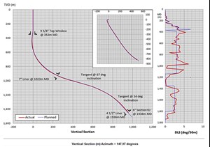
Well 9 was designed to have two new hole sections, Fig. 1. The well was sidetracked from a shallow depth of 353 m, utilizing a mechanical-set, single-trip 9⅝-in. whipstock. Upon running in and orienting the whipstock, the system was set in place by means of a set-down weight on top of a 9⅝-in. bridge plug that was set during the wellbore clean-out operations, post-plug-and-abandon operations of the mainbore. The successful whipstock anchor was set, and the lead mill, together with the middle and upper watermelon mill assembly, was released from the whipstock ramp.
Milling operations then began, and a successful 6-m window was created, together with a 10-m rathole drilled with the same assembly. Mill gauge and wear evaluation on surface showed good window creation, together with the corresponding metal swarf collection. A BOP cleaning tool, by means of vortex creation, was used to avoid the cycling of BOP rams while cleaning. The 8½-in. and 6-in. hole sections were then drilled, and the 7-in. and 4½-in. hydraulic set liners were set and cemented in place, together with pressure point evaluations being performed in open hole. Completions with retrievable tubing-conveyed perforation (RTCP) were run, and the well was completed successfully.
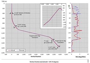
Well 13 was designed to have three new hole sections, Fig. 2. As with well 9, the initial drilling start-up operations were almost the same, with some changes. A 13⅜-in. whipstock was set on a shallow cement plug at 421 m, which was dressed and tagged during the P&A operations of the mainbore. The successful whipstock anchor was set, and the lead mill, together with the middle and upper watermelon mill assembly, was released from the whipstock ramp. Milling operations then began, and a successful 6-m window was created, together with a 10-m rathole drilled with the same assembly.
Mill gauge and wear evaluation on surface showed good window creation, together with the corresponding metal swarf collection. A BOP cleaning tool, by means of vortex creation, was used to avoid the cycling of BOP rams while cleaning. The 12¼-in., 8½-in. and 6-in. hole sections were drilled, and the 9⅝-in. casing, 7-in. and 4½-in. hydraulically set liner were cemented in place. Pressure point evaluations were performed in open hole. Completions with integrated tubing-conveyed perforation (ITCP) were run, and the well was completed successfully.
All through the operations, ERD techniques and MPD methods were implemented and executed to ensure the drilling objectives were met. Overall, the use of MPD successfully delivered two wells that would otherwise be much more challenging to deliver:
- Successfully delivered the severely depleted wells, which would not have been possible without MPD, as there was only a 0.5-ppg margin between pore and fracture pressure in the reservoir section.
- Successfully captured the formation pressures, using a formation tester in the drilling BHA for both wells, allowing sufficient circulating rates to downlink to the tools, clean the well and obtain data in real time.
- Allowed higher flowrates for effective hole cleaning while drilling in an ERD environment.
- Use of MPD allowed for a reduction in mud density to accommodate the lower-than-expected, depleted formation pore pressures.
- Successfully cemented the 7-in. and 4½-in. liner with managed pressure cementing (MPC), in three of five hole sections.
DRILLING HAZARDS
The following drilling hazards were identified on the basis of design stage, and mitigation plans were carried out during planning and operations.
Wellbore instability. A wellbore stability study was performed for the WD field, and empirical evidence from the previous wells suggests a higher mud weight is required to drill the well and is determined by the wellbore stability, especially in high- and long-angle wells. In a certain identified weak group sand, the shear failure of this formation is evaluated as being sensitive to the inclination of the well.
While drilling through this sand, the recommendation was to have a minimum ECD and equivalent static density (ESD) of 10.5 ppg, to keep the wellbore stable at minimum shear failure and to keep the wellbore cyclic pressure effect at a minimum during drilling and connections. The recommended MW and ECD is meant to be above 12.0 ppg for drilling the production hole section. This is mainly to reduce the risk of drilling through unstable formations. Therefore, the mud weight strategy was to start with a low static MW that covers the pressure ramp high pressure formation and apply MPD to keep the bottomhole pressure constant, to stay within the pressure window.
Losses while drilling. As risk mitigation action for drilling past the weak sand, the ECD management is now crucial and, therefore, the best practices for ECD management were adhered to. The synthetic-based mud (SBM) density for drilling this section was at 9.0 ppg, with lower high-end rheology being maintained for optimized ECD control to avoid losses. With the MPD system in place, losses are detected early and adjustments in terms of surface backpressure or mud pump flowrates are made. With the low static mud weights, the stress on the wellbore was also reduced, together with maintaining a constant bottomhole pressure (CBHP) environment.
Losses while cementing. Given the potential losses while cementing, due to ECD during displacement, especially for the surface hole section, a low-weight cement slurry was used to mitigate this risk. Losses during cementing would affect the cement quality behind casing and might jeopardize the well’s integrity. Therefore, the cementing for the well was designed and executed with two slurries for both surface and the production hole section to give an assurance of having a good cementing job for the wells. The usage of managed pressure cementing in these wells was planned and executed as per plan. High ECDs were seen when displacing the well from kill weight mud back to drilling mud.
To avoid the possibility of fracturing the depleted zone gradient and keep the wellbore pressure constantly overbalanced, the MPD system was used to compensate for ECD while:
- Pumping the pre-flush, spacer with LCM technology and cement slurry
- During the pumps-off events on the cement pump
- While switching between pumps.
The MPD system also allowed higher flowrates while pumping the spacer for mud removal purposes.
Pressure ramp. Leveraging the MPD system to be used for drilling the pressure ramp section, MPD surface back pressure was applied to keep the bottomhole pressure constant and overbalanced to the pore pressure, thus reducing the possibilities of taking in an influx. Even in sections where the static MW was underbalanced to the pore pressure and minimum stability requirement, MPD applied sufficient pressure to maintain constant bottomhole pressure, overbalanced to the pore pressure and achieving wellbore stability requirements.
EXECUTING ERD/MPD
Well 9 had a 957-m horizontal departure (ERD depth ratio 1.33:1), and well 13 had a 3,922-m horizontal departure (ERD depth ratio 2.77:1) from vertical depth. Well 9 was drilled first, followed by well 13. All ERD and MPD practices and design were implemented in well 9 as a learning curve before drilling the more crucial well 13. From the identified drilling hazards, both the wells were equally challenging in their own ways.
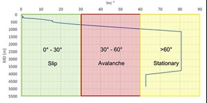
Well 13 was predominantly in the stationary zone, Fig. 3. Therefore, in terms of engineering and operations, it was assumed that no effective hole cleaning will take place, unless both flowrate and drill-string rotation are greater than hole cleaning thresholds. This was the basis for the conveyor method.
The 12¼-in. section drills through the avalanche zone, landing out within the stationary flow regime. The section was drilled with a bent motor housing (1.5° bend) and as such, hole cleaning could become challenging, due to limited surface rotation. To compensate for the reduced rotations, flowrates and fluid rheology was maximized within system limits. Tripping practices also were adjusted to ensure good hole condition for installation of the 9⅝-in. casing string.
The 8½-in. section held tangent at 81° inclination before dropping inclination to 62° at 2°/30 m to land within the reservoir. Given this trajectory, cuttings accumulation would appear at the top of the drop section and was considered a higher risk during tripping operations. The section largely remains within the stationary regime, only dropping back to the avalanche regime towards well TD.
Given this, good hole cleaning parameters and fluid rheology were required to effectively clean the hole and reach section TD. A rotary steerable system was utilized to greatly help with hole cleaning efficiency, lifting cuttings off the low side of the wellbore and into the high-velocity flow stream. With the use of managed pressure drilling techniques, flowrates were maintained above the ERD minimum recommended annular velocity (45 m/min.) throughout the section. This aided in hole cleaning efficiency and improved drilling performance.
The 6-in. section was drilled with a rotary steerable assembly, and it provided sufficient parameters for effective hole cleaning across the open hole and 7-in. liner section. However, lower annular velocities were observed within the 9⅝-in. casing (above 7-in. TOL) and would have resulted in cuttings accumulation at the base of the avalanche zone. With the high flow rate, pipe rotation and controlled ROP, this issue was mitigated. An intelligent circulation sub (telemetry based) included within the BHA facilitated higher flow rates for wellbore clean-up and remedial hole cleaning at the top of the 7-in. liner which alleviated any cuttings loading within this area.
The use of MPD mitigated the risk of losses to the major fault zone, as observed in offset well 18. MPD was identified as a technology to mitigate the past campaign issues. The objectives of utilizing MPD were to:
- Improve safety and efficiency to drill the well to planned TD without incidents or equipment failures.
- Improve early kick detection to cater for the reduced kick tolerance in the well design and early loss detection for managing the ECD/ESD.
- Reduce wellbore fatigue and stressing the wellbore while drilling and making connection by applying the constant bottomhole pressure technique with a deviation of less than 0.5 ppg equivalent mud weight (EMW).
- Manage the overbalance in the wellbore to always be above 150 psi to the pore pressure and eliminate hole instability issues.
- Provide early response to an influx event and minimize kick volume within the limitation of the shoe strength and the surface equipment.
- Provide early response to a loss scenario by varying the EMW downhole.
- Elimination of any contingency casing strings.
- Manage the expected pressure ramps before and after the reservoir sections.
- Perform dynamic formation tests without changing the MW’s.
Both wells were designated as sidetrack ERD development wells. The approach for the application of MPD is to have maximum flexibility to control and manage the wellbore pressures during the drilling of the 12¼-in., 8½-in. and 6-in. hole sections. With the expected narrow margin available between pore and fracture pressure upon the introduction of the ECDs, all the drilling sections were drilled with a low mud weight, either at/near balance to the pore pressure or even underbalanced. This means that when circulation is stopped, the hydrostatic pressure (ESD) of the mud will either be at balance or underbalanced to the pore pressure.
Therefore, MPD was utilized to keep the well overbalanced to pore pressure by utilizing the surface back pressure (SBP). As a minimum, 150-psi overbalance was required to be maintained above the pore pressure. This maintained well integrity and kept well control in check.
Real-time pressure while drilling (PWD) in the drilling BHA was used to correlate to the MPD well model for automated choke control. Gas readings also were used as an indication that sufficient overbalance was being maintained. Site-specific communication procedures were developed to ascertain the limits and alarm at the wellsite, together with MPD wellsite training within the rig crew.
At section TD for the wells, the kill mud weight chosen was based on the density required to maintain the wellbore stability, due to the ERD nature of the well and the coal stringers present in the lithology. The concept of maintaining a constant bottomhole pressure between drilling, making connections, tripping in, tripping out and killing the well was maintained all through the operations, to avoid cycling the wellbore pressure and imposing fatigue on the wellbore.
For the ease of operations, the elected method used for MPD influx circulation was that any measurable influx detected by the MPD system will be controlled by the automated MPD system, by increase of the SBP and within the limits of the SBP in relation to the equipment and well. By doing so, the influx is kept small, avoiding its further expansion. Once the influx has been controlled, the well control operations of circulating the influx out safely will be performed by the rig.
Entrained gas in the system, by identification of connection gas, background gas and trip gas, will be considered as a non-measurable influx. These events can be safely circulated out through the MPD system, if identified properly and the appropriate limits on surface backpressure are adhered to following the MPD operations matrix.
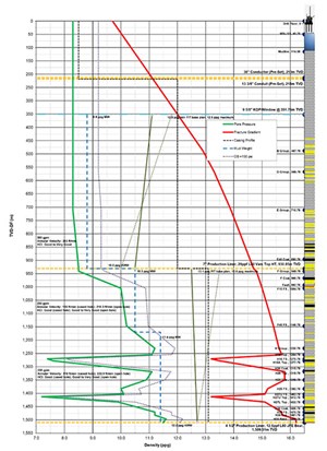
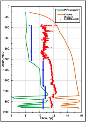
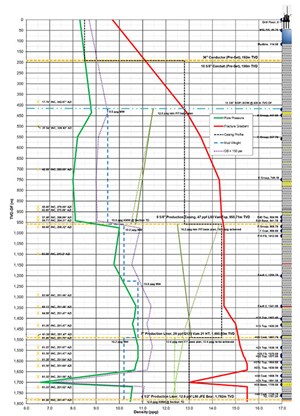
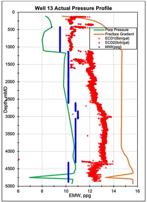
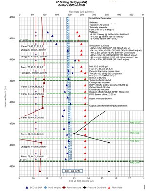
As part of the design and well control strategy, the mud gas separator on the rig was evaluated to ascertain the operating envelope, based on the highest drilling MW. These results tied into the creation of the MPD well control operations matrix. Both wells were designed, as per the well delivery process. Being a development well, the known pressure was taken as a basis for design, and the issues encountered in the offset wells were taken into consideration for the well design. The planned and actual pressure profiles are shown in Figs. 4, 5, 6 and 7.
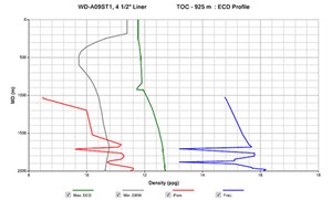
The 8½-in. hole section for well 9 was drilled with a 500-gpm flowrate on a motor assembly, with low MW’s of 8.8 ppg, and MPD SBP was maintained constant above the minimum stability requirement of 10 ppg. The 6-in. hole section was drilled with a 250-gpm flowrate, utilizing an RSS assembly. The section was split into two parts, where the first half of the section before the depleted reservoir was drilled with 10.5ppg MW (in anticipation for losses), and the second half was drilled with 10.8 ppg MW. Initially, 11.4 ppg was planned, however, anticipating the reservoir was depleted even more, the MW was reduced to 10.8 ppg and then 10.5 ppg in the reservoir section. All through the section, constant bottomhole pressure was maintained to be equal to drilling ECD. On both sections, a deviation of 0.5 ppg between drilling ECD and static EMW (ESD) was seen, as shown in the ECD plot.
At section TD, without killing the well and maintaining stability with constant bottomhole pressure, formation pressure tests were performed with the required flowrates for the tool to operate. This proved to be very beneficial in terms of operational timing and wellbore condition.
The 12¼-in hole section for well 13 was drilled with a 1,200-gpm flowrate, utilizing a motor assembly with a low MW of 9.5 ppg, and MPD SBP was maintained constant above the minimum stability requirement of 10.5 ppg. The 8½-in. hole section was drilled with a 700-gpm flowrate on an RSS assembly, with low MW’s of 10.2 ppg for the first half of the section before the Fault I (Major Fault) and then increased to 10.8 ppg for the second half after penetrating the fault.
MPD surface backpressure was maintained constant above the minimum stability requirement of 12.0 ppg throughout. The 6-in. hole section was drilled with a 250-gpm flowrate, utilizing an RSS assembly and with a low MW of 10.2 ppg that was underbalanced to the pore pressure, Fig. 6. Prior to drilling out this section, a dynamic formation integrity test (FIT) was performed to ascertain the formation strength. With MPD in place, 490 psi of SBP was applied to achieve the 13.5 ppg EMW, using an underbalanced MW.
At section TD, formation pressure tests were performed with the required flowrates for the tool to operate without killing the well and maintaining stability with constant bottomhole pressure. This again proved to be beneficial in terms of operational timing and wellbore condition. All through the section, CBHP was maintained to be equal to drilling ECD, overbalanced to the pore pressure. On all three sections, a deviation of 0.5 ppg between drilling ECD and static EMW was observed, Fig. 7.
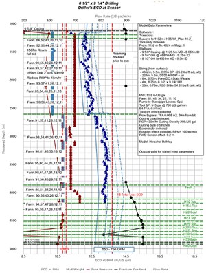
A proven point that was seen during operations, the ECD’s in the 8½-in. hole section for well 13 were maintained constant and trending below the well 18 total loss ECD of 13.5 ppg, maintaining the required stability requirement of 12.0 ppg, Fig. 8. Flowrates required for good hole cleaning practices also avoided the annulus from loading up and creating ECD-induced losses. ECD’s in the 6-in. hole section were maintained constant and trended, maintaining the required stability requirement of 12.0 ppg.
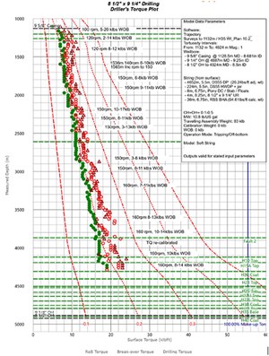
Flowrates required for good hole cleaning practices also avoided the annulus from loading up and creating ECD induced losses, Fig. 9. For an ERD well, good drilling practices, high flowrates, rotation and optimum low-end rheology of the mud maintain the conveyor belt method while drilling these wells. This proved to be beneficial, as the friction factors while drilling the wells were low and trending within expected simulated factors, Fig. 10. This was attributed to good hole cleaning practices, good hole conditions and stability.
MPC also proved to be a great success for both well 9 and well 13. Out of the five hole sections between the two wells, three were cemented in place, using the MPC method. The risk of fracturing the depleted sands and the fault sections was a motivation to engineer the MPC method to fit within the well limits. The objective of maintaining the EMW in the well, to be within the wellbore stability limits and the ECD that the well has been exposed to, was also the prime objective. Displacing the well from kill MW to drilling MW and introducing the cement slurry conventionally would fluctuate the wellbore pressures a great deal and risk inducing losses.
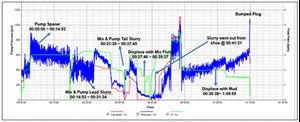
During the cement job, six pump-off events were identified, which would put the well in an underbalanced condition without some SBP. Thus, a SBP schedule for each pump off event was prepared and followed through. MPD successfully applied the required SBP to maintain CBHP, which maintained wellbore stability. Even with a low FG at the depleted sands, there were no measurable losses during displacement of the cement. An LCM spacer was also used in the cement slurry recipe to aid the MPC method. The cement pump job playback showed a gradual pressure increase, as cement was displaced up-hole, Fig. 11. A good volume of cement spacer was circulated back to surface after setting the liner top packer. All indications support a successful casing and liner cement job with cement at, or very near to, the top of liner and planned top of cement.
Mud rollovers between drilling mud and kill mud, and back to drilling mud, proved to be advantageous with the MPD system. Constant bottomhole pressure was maintained, and wellbore fatigue was eliminated. The anchor points for MPD control were set at the depleted sand zones. This method was applied whenever the MPD system was online.
DRILLING FLUIDS
The MWs chosen to drill the hole sections were finalized, based on limitations in terms of the wellbore pressures and required overbalance to be maintained. Note that with MPD in place, the circulation system becomes a closed loop system, and the addition of SBP becomes apparent in the hydraulics.
The drilling sections were engineered with a low MW to be used to keep minimum static overbalance against the pore pressure and be within the limitations of the FIT value with ECD in considerations. The kill MW was designed to support minimum wellbore stability values and induced drilling ECDs to keep pressure fluctuation in the wellbore as minimal as possible. With MPD in place, the downhole pressure was maintained at a constant pressure throughout the drilling sections, Fig. 12. The drilling fluid selections were based on the well requirements, formation pore pressures and wellbore stability. The mud system utilized was based on the obtained offset wells data, BOP in place and MPD mode while drilling.
Strategies were also in place to drill the depleted sections with an engineered wellbore strengthening solution, using agents whereby suggested formulation was mixed into the SBM system and tested across a 508-um slotted disc to simulate the fracture width, Table 1. The wellbore stability issues while drilling through coals and fault zones were also addressed by addition of bridging materials into the mud system as a preventive measure prior to penetrating these zones, Table 2.
Zero fluids and cementing-related NPT throughout the drilling phase of the campaign were encountered. Effective fluids planning and execution, as mentioned above for lost circulation prevention and wellbore strengthening methods during drilling of depleted zones, were applied to the mud system, as the coal and fault zones were being approached. The stable SBM fluids system properties (Table 3), maintaining low shear rate viscosity at optimum levels for good hole cleaning while keeping the LGS content below the 7% level, provided good cuttings carrying capacity for hole cleaning. They also provided excellent hole stability, as well as achieving desired friction factor levels. An LCM decision tree (particle type) was in place to combat potential losses while drilling.
CEMENTING
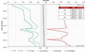
The ECD profile while cementing the 4½-in. liner in well 9 is shown in Fig. 13. By using the MPD system, the ECD profile of the well will be maintained overbalanced by compensating for a pump-off scenario between operations, thus maintaining integrity and the 150-psi overbalance. The ECD is also below the limits of the fracture.
Pre-flushes and spacers played fundamental roles to achieving zonal isolation in the wellbore. For a cement slurry to create a proper and effective bond, the surface of the casing and formation must be clean of drilling fluids. A spacer is used to displace fluid from the annulus, while a pre-flush is used to thin and diffuse any leftover drilling fluid particles. With a 4-bpm pre-flush and spacer displacement rate, the mud removal was effective. The rotation of the liner also helped with effective mud removal. In conclusion, the MPC method, together with an LCM spacer technology-achieved successful cementing for the well sections.
VALUE DELIVERED
Applying a combination of extended-reach drilling techniques with managed pressure drilling achieved the following:
- Successfully drilled both wells with constant bottom pressure to minimize BHP fluctuations during the drilling and connection process.
- Always maintained desired ECD at bottom and overbalanced formation pressure while drilling and cementing, and during mud rollovers between phases.
- Drilled with no well control issues.
- MPD system was used to compensate swab pressure by applying surface back pressure during strip out of hole in 8½-in. and 6-in. hole sections.
- Successfully maintained borehole conditions, avoiding kicks, hole stability issues and mud losses.
- Able to drill hole with an optimized flowrate for hole cleaning with an ERD architecture.
- Able to manage the ECD and ESD within the upper and lower pressure limits of the well.
- Successfully drilled and performed open-hole formation evaluations and cementing with a statically underbalanced mud weight.
CONCLUSION
The objectives of well 9 and well 13 were successfully achieved. The utilization of MPD, together with ERD engineering and operational practices, mitigated all the issues seen with the previous campaign wells, namely well 18 where narrow mud weight margin, wellbore stability, kick and loss circulation cycles, drilling performance issues and pressure ramps were seen. The improved drilling performance and operational efficiency proved that MPD, utilized in a complex ERD well, enabled the operator to mitigate drilling challenges and reach previously unproduced reservoirs.
- Advancing offshore decarbonization through electrification of FPSOs (March 2024)
- Subsea technology- Corrosion monitoring: From failure to success (February 2024)
- Driving MPD adoption with performance-enhancing technologies (January 2024)
- Digital transformation: A breakthrough year for digitalization in the offshore sector (January 2024)
- Offshore technology: Platform design: Is the next generation of offshore platforms changing offshore energy? (December 2023)
- 2024: A policy crossroads for American offshore energy (December 2023)

