Integrated approach drills unstable carbonates with superior borehole quality for multi-stage completions
Hydrocarbon bearing reservoirs in the field are located in excess of 12,000 ft TVD, in carbonate and sandstone formations, with high pore pressure and blowhole temperature exceeding drilling bottom hole assembly (BHA) limitations (above 300°F). The wells are drilled in six to seven sections, with 5 7/8-in. size across the reservoir. Two main completion types are used; the selection on those is based on the reservoir characteristics obtained by the open-hole logging and expected production rates. Both options available are the multi-stage fracing (MSF) with several fracing stages of open-hole packers, and fracing sleeves and cemented liner, which will be perforated in the future at pre-selected intervals.
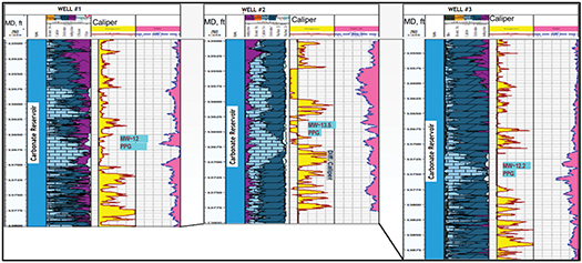
The deploying of MSF strings might be compromised by not reaching the bottom, due to several reasons. Tight spots, large washout areas and enlargement zones, due to wellbore instability, are the most common ones and not properly isolating the required reservoir layers is risky. When an MSF is too risky to run and successfully reach the bottom, the contingency is to run and cement a production liner. In terms of production, the MSF is preferred over the cemented liner; that is why proper planning and mud weight selection are the key to guaranteeing the quality of the borehole. The MSF will require a gauge hole, so the isolation packers of the MSF completion string can be set for effective stages of isolation from each other. Strangely in vertical holes, regardless of the mud weight used in offset wells, the hole quality and level of enlargement were found with significant differences between the wells, Fig. 1.
In some cases, two PPG differences in drilling fluid weight did not improve the wellbore quality and keep the hole stable. Offset wells located within only 3 km from each other got equally poor wellbore conditions, regardless of utilized mud weight.
Well design description. Basis of design considers two main well designs—the heavy well design and the light well design. The heavy well design consists of seven casing strings to reach the reservoir, and the slim hole design is only one casing less. The selection of the well design resides on the risk identified during the offset well analysis. Several wells in a radius of 2 km, 5 km, and sometimes 10 km, are analyzed to assess the different risks from differing formations. Based on the probability and severity of the risk, the well design is selected and, from there, the trajectory is adjusted to achieve the target reservoirs trouble-free.
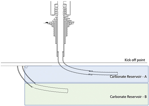
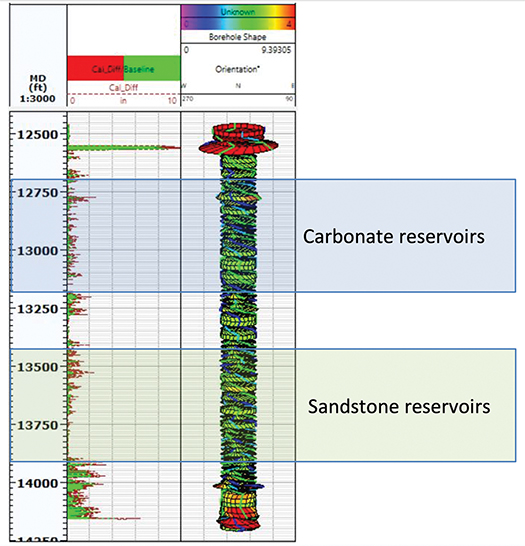
There are two main carbonate reservoirs where the horizontal wells are drilled in this block, Fig. 2. Both reservoirs’ combined thickness does not exceed 600 ft. However, that additional footage makes a major difference when a build/landing section is initiated in one section. The landing point needs to be reached in the shallower reservoir layer of carbonate reservoir B.
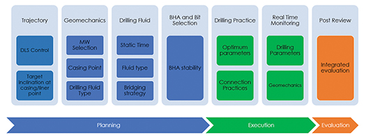
In vertical wells, up to four reservoirs can be combined in the same section. The wellbore quality needs to be such that data acquisition is not compromised, including pressure points and samples extraction. If the wellbore condition deteriorates, the data acquisition will not be possible, and reservoir data are missed to better assess rock properties and production estimations. Many factors affecting wellbore stability were studied. An integrated approach was finally established to minimize the negative impact on the hole while drilling. The methodology goes through the entire process, including planning, execution and evaluation phases. The factors affecting wellbore quality are summarized in Fig. 3.
INTEGRATED APPROACH (BUILD-UP/LANDING SECTIONS)
The proper planning and flawless execution of the build-up/landing section in horizontal wells are the keys to delivering reservoir sections with suitable wellbore quality to run a lower completion. Whether it will be MSF or cemented liner, one should minimize operational exposure while drilling a 5-7/8-in. reservoir hole.
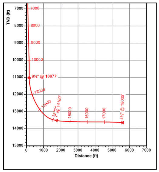
Trajectory planning. The build-up/landing section (Fig. 4) is drilled across interbedded formations. The two most critical objectives of the section are: 1) to case fully or most of the caprock; and 2) land the well at the planned inclination. Directional work is built in accordance with the responses from different formations. In the build-up/landing section, the trajectory is built from 0° almost to horizontal, leaving only several degrees of inclination to complete in reservoir section and, normally, all trajectories have a 2D profile. Based on the formation, the DLS can be planned up to 4.5°/100 ft. It is important to stay above the planned trajectory during the execution, especially when actual formations are met shallower, normally between 30-50 ft, TVD. Several BHA configurations have been applied to optimize the directional work and maximize ROP. The curve sections have been drilled with RSS BHAs, in their two modalities: point the bit and push the bit looking for shock reduction and performance improvement. The motorized RSS BHA has been tried, and due to unavailability of tools, even PDM with a bent housing of 1.15° was tried.
BHA design. Since the section is deep already, and the typical mud weight of drilling fluid used ranges between 14 and 19 ppg, high pump/standpipe pressure is expected on the surface. Therefore, minimizing pressure losses along the drillstring is required to avoid frequent rig pump failures. Drilling with this high mud weight and the limitation of the mud pumps can compromise the hydraulic power supplied to the directional tools required to steer. In some cases, it was necessary to sacrifice the flowrate to manage the high pump pressure. This reduction affected the surveying tool operation and HSI at the bit. Field experience showed that the best application in the curve section is a point-the-bit RSS. It requires less pressure drop for the power supply, reducing the total standpipe pressure and the chance of potential formation washout. Internal tool modifications, such as the right size of pressure restrictor installation, must be planned in advance to avoid unnecessary trips during drilling.
When landing, the well is planned to be on the caprock of carbonate reservoir A. A push-the-bit RSS is preferable, as higher DLS can be achieved when mud weight permits. In one extreme case, the curve section had to be drilled with a PDM BHA. Increasing the actual time to reach the section’s total depth resulted in twice-longer than the average time with an RSS BHA. Additionally, several extra precautions, to avoid stuck pipes while sliding, had to be in place.

Drilling fluid treatment. With the high mud weight, usually used in the build-up/landing section, the risk of stuck pipe increases, due to high overbalance (2,000-3,000 psi). Hence, slim BHA, specific connection practices customized for different ranges of overbalance, and a bridging strategy for the drilling mud treatment are applied. Mud is treated regularly with bridging material of different sizes and concentrations; it helps to support unstable zones of the wellbore and plugs’ porous intervals (if present) across the wellbore.
Jar placement. When drilling across carbonate reservoir A in the build-up/landing section, the chances of getting stuck differentially are higher. Under this scenario, the placement of the jar plays a vital role in making the jar work effectively. After several analyses conducted in various horizontal wells and multiple simulations, the recommendation is to keep the jar away from the porous formation. This will ensure that jar will be activated in case of differential stuck pipe with the BHA. During the execution, the proper limits on WOB are communicated to the driller, as the jar in this section will be run in both tension and compression along the section.
Geomechanics and structural analysis. The geomechanical and structural study is conducted for build-up/landing sections to analyze the best liner point depth to isolate the unstable cap rock and minimize or fully eliminate the footage of caprock to be drilled in the reservoir section. There are two reasons to reduce the cap rock exposure; one is related to the instability observed in some wells just below the shoe, Fig. 5. This instability was created, due to the difference between the required mud weights to keep the high pressurized caprock undisturbed and the mud weight required to drill the horizontal section across the layer of interest, which often is depleted.
The larger the length of the caprock in the lateral section, the higher the probability of leading to instability issues just below the previous shoe and, in the worst-case, completed wellbore collapses, and there is a stuck pipe situation. Due to instability below the shoe, hole enlargement can result in difficulty passing through with a lower completion assembly. The second reason for reducing the caprock exposure is oriented to the drilling performance. The longer the cap rock exposure to be drilled in the slim 5 7/8-in. hole, the higher the probability of BHA resulting in a premature bit and downhole tool failures, due to the excessive shocks and vibrations.
Geomechanical and structural models are created, based on logging data from the offset wells. They help identify potentially unstable intervals and suggest the most accurate mud weight to keep the wellbore stable. Normally, caprock will require higher mud weights than the other reservoirs underneath. Based on caprock thickness and the targeted reservoir layer in the next horizontal section, the previous liner point is successfully deepening to fully cover the most unstable caprock. The full covering of the caprock allows one to safely drill the lateral section with a reduced mud weight that will prevent the sticking tendency in the horizontal section.
INTEGRATED APPROACH (VERTICAL SECTIONS)
Superior wellbore quality is targeted when drilling vertically across the hydrocarbon reservoir to ensure planned MSF or cemented liner completion will be run. It was observed that multiple factors are affecting the hole quality delivered after the drilling phase is finished. In the challenging environment, an integrated approach has been applied to understand the factors, improve their impact on the wellbore quality, and minimize risk in the field operations.
Vertical wells have a different target reservoir to be reached; it targets the deeper formations that consist of sandstones. Secondary targets will remain in the A and B carbonate reservoirs for future sidetracks and production. When vertical wells are drilled, the landing of the previous section is not a challenge anymore. It was observed that good hole quality could not be achieved by maintaining minimum required overbalance, as per industry standard, on the formation while drilling.
Challenges. The challenges in vertical wells are high downhole vibrations, poor ROP, and the natural building tendency of the formation. In attempts to improve the performance, the natural reaction from the driller was to perform a drill-off test looking for the optimum parameters to increase the ROP. What was noticed is that some excessive parameters were not increasing the ROP but simply spending more energy to drill a rock that doesn’t need that energy to be drilled. The excessive energy was dissipated through the drillstring against the formation, and eventually, an over-gauged hole was recorded by caliper.
Geomechanics and structural analysis. Firstly, the offset well analysis is performed, and a geomechanical study is done to suggest the minimum mud weight. Geomechanics recommend mud weight from the lithology perspective; it has been observed that a higher amount of dolomite in the composition causes unstable hole intervals. At the same time, mud weight is not being raised too high to avoid inducing losses, as the formations drilled through are known to be fractured. The main inputs to the geomechanical and structural models come from the pressure points, the samples taken from the reservoir, open-hole logging, such as porosity, resistivity and mud logging to identify the lithology.
Another important factor contributing to the poor wellbore quality that surfaced after this study was the type of carbonate lithology drilled through. A certain pattern of hole enlargement was observed in several wells, which prompted the petrophysical lithology analysis on those wells. The lithology analysis revealed that most of the enlarged intervals in these wells were associated with dolomite lithology. Further analysis suggested that dolomitic intervals are relatively stiffer (higher young’s modulus) than other lithologies, which means these intervals experience more differential stresses due to higher stiffness. Hence, breakouts can easily cause hole enlargement.
Real-time monitoring. When drilling horizontal wells, LWD is implemented where caliper and porosity are measured, and geomechanics engineers review it in real-time to suggest changes of the mud weight if needed. It showed great value, especially considering challenging strike-slip stress regime environment because breakouts are formed on top and bottom of the hole, making it hard to trip or reciprocate the string, which creates a substantial risk of a stuck pipe situation. Unlike in horizontal wells, in vertical wells, LWD does not run. Therefore, only surface parameters, such as torque, ROP, and weight on bit, are monitored to assess the drilling environment.
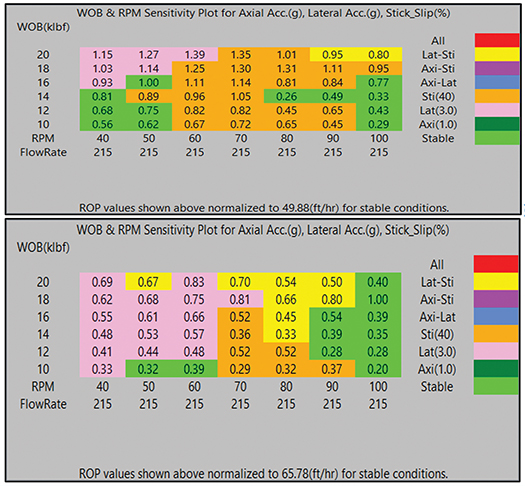
BHA design. Additional wellbore disturbances are coming from the BHA, itself. The main criterion for selecting BHA is to provide stability of the drilling string and efficient drilling, preferably in a single run. Downhole vibrations cause premature failure of the downhole tools and lead to breakouts that negatively affect hole conditions. Therefore, the placement of the packers in an MSF lower completion assembly has to be changed, compromising gas production. Engineering analysis is done, using integrated dynamic system software where actual drilling can be simulated and different BHAs can be compared in the planning phase. The main outputs are the best drilling parameters to be used while drilling to ensure stable BHA behavior and the best possible ROP. Fig. 6.
In Fig. 7, the simulation output presents where the range of WOB is placed on the Y-axis, and RPM and flowrates are on the X-axes. The interception of the combination of the mentioned drilling parameters gives the coefficient to be multiplied by the normalized ROP chosen for the particular interval. The color scale on the right represents the level of the downhole shocks and vibrations. Based on the analysis and field trials, motorized BHA showed the best performance and provided better wellbore quality, based on better drilling dynamics. As well, PDM, itself, is capable of absorbing certain levels of downhole shocks and vibrations.

Drilling fluid selection. In the majority of the cases, water-based mud is fit for drilling purposes. However, whenever an extensive logging program is planned, including pressure point measurement and fluid samples extraction, oil-based mud is chosen to minimize the risk of being stuck with logging tools. This also avoids mud degradation, due to long-time open-hole exposure under high-temperature environment. Database with more than 50 wells has been collected to identify the time limit of open-hole static exposure after what lower completion can be run successfully without additional conditioning trip.
RESULTS
The curve section in multiple wells with a wide range of overbalance has been drilled. Also, DLS has been varying between 1-6°/100 ft. Different directional drilling systems were utilized, and even drilling liner points were deepened inside the reservoir to various depths, and the enlarged areas below the liner shoe were eliminated. Carbonate and sandstone reservoirs have been drilled vertically with different mud systems, BHAs and bits allowing the running of MSF completion systems successfully in multiple wells. Exceptional wellbore quality has been achieved (Fig. 8) below, where all four production zones were combined in one section together, the overbalance on each of them varying between 700 and 2,500 psi. Other results are listed below:
- The rate of the shoe to hoe runs across the reservoir section increased 30%.
- In seven horizontal wells, liner point of build-up/landing section was deepened, and caprock was covered fully or up to 80% to 90% of TVD.
- In 2020, no stuck pipes events with 5 7/8-in. BHA while POOH across the enlarged area below the previous liner shoe.
- 100% of the vertical wells were completed with MSF systems, as per plan.
- Standard practices and approaches to planning the build-up/landing sections and vertical sections across the reservoirs were developed and spread across the entire project.
- Carbonate and sandstone reservoirs were combined in the same section, with superior borehole quality.
CONCLUSION
The multidisciplinary approach integrates different domains to innovate and significantly drill challenging reservoir sections. It also demonstrates the pertinence of the strategy to improve drilling efficiency, increased rate of lower completion deployed to the bottom.
The lessons learned and the best practices captured for the entire field dramatically changed the drilling strategy regarding time, cost and reservoir quality. One looks for the same delivery improvement from BHA, mud type and weight, casing point selections, and trajectory optimization to improve the quality, to reduce the drilling risks for better well delivery. This integration was achieved, using innovative technologies from Schlumberger to add value.
ACKNOWLEDGMENT
The authors would like to thank Schlumberger for the support provided during this project. We are also grateful to other company individuals, who contributed to the planning and successful execution of this project. This article contains excerpts from IPTC paper 22053, presented at the International Petroleum Technology Conference, held in Riyadh, Saudi Arabia, February 2022.


- From post-mortem to real-time: A scalable approach to fracture diagnostics (May)
- The benefits of Simulfracs (January)
- Molecular fracing: A rock-focused, field-ready stimulation chemistry (January)
- Halliburton’s ZEUS IQ™ powers the first fully autonomous fracturing platform with closed-loop automation (January)
- The power of less: Surface pressure containment ecosystem autonomously delivers continuous sanding with fewer pump swaps (October 2025)
- Smarter well interventions accelerate productivity (July 2025)
- Subsea technology- Corrosion monitoring: From failure to success (February 2024)
- Applying ultra-deep LWD resistivity technology successfully in a SAGD operation (May 2019)
- Adoption of wireless intelligent completions advances (May 2019)
- Majors double down as takeaway crunch eases (April 2019)
- What’s new in well logging and formation evaluation (April 2019)
- Qualification of a 20,000-psi subsea BOP: A collaborative approach (February 2019)

