Pump sand protection technology extends ESP run life in unconventional wells
Extending the life of electric submersible pump (ESP) systems has gained significance, as more wells rely on ESPs. The run life and performance of artificial lift pumps are sensitive to solids particles in the produced fluid. ESP run life and performance drop significantly, as solid particles increase. Additionally, solids increase well downtime and workover frequency required to replace the ESP.
Solids particles that frequently flow through artificial lift pumps include formation sands, hydraulic fracturing proppants, cements and eroded or corroded metal particles. Downhole technologies, designed to separate the solids, range from low-efficiency cyclonic separation to highly efficient, 3D, stainless-steel wool screens. Downhole vortex-induced desanders have been in use for decades in conventional wells, where they principally protect pumps from large particles during production. However, unconventional wells suffer from intermittent slug flow, which causes the existing downhole vortex-induced separator technology to work only intermittently.
APPLICATION CHALLENGE
Several different variants of combination sand control screen and downhole-vortex-induced desanders have been proposed to protect ESPs. However, all left gaps in pump protection and production performance, due to uncertainty in produced solids size distribution and volume from each well. The uncertainty increased sand control assembly lengths, which reduced ESP setting depths, limiting reservoir drawdown potential of the ESP and negatively impacting well economics. Deeper setting depths in unconventional wells is preferred. However, suspending long, rigid sand control assemblies, using desanders and bull-plugged mud anchors inside casing sections with high dogleg severity, was limiting improvement of the mean time between failure for the ESPs. Erosion of the inner tube was another aspect not fully evaluated with this design.
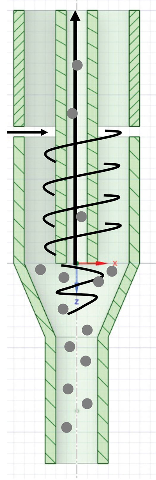
The authors of a 2005 paper presented the experimental results from a downhole sand separator based on swirl tubes (Fig. 1), which depend on cyclonic action and gravity, to show the separation efficiency dependence on the oil viscosity, flowrate and particle size. They showed that efficiency of the separator is largely dependent on the terminal velocity of the particle. Separation efficiency deteriorates with a drop in flowrate, decrease in solid particle size and increase in oil viscosity, Fig. 2. For a typical swirling tube downhole separator, as the particle diameter falls to ~100 µm, the separation efficiency decreases to ~10%. Additionally, with the higher flowrates, vortex-induced separators are subject to erosive wear, which affects the operational life of the structural components.

The next logical alternative would be to use 2D sand control screens with a defined slot width. When selecting a screen to filter solids in production from a conventional or unconventional well, grain size and distribution are important considerations, but they may be unknown. The solids may originate from the reservoir, but they can vary from heel to toe; alternatively, the screens may need to filter sand from hydraulic fracturing. In either case, the cost of solids collection, analysis, and testing may be prohibitive.
If 2D tubing screens are not configured appropriately, the results can be detrimental to the economics of the well. Sand screen pores that are too small may result in premature plugging, halting production and requiring a remedial workover. If they are too big, they allow solids to freely enter the production flow, which can erode tubing, destroy artificial lift pumps, wash out surface chokes, and fill up surface separators, requiring sand jetting and disposal. This situation leaves a need for a simple, cost-effective solution that can increase pump life and encompass a wide distribution of sand sizes.
To address this need, a study was done on the use of a valve assembly in conjunction with a stainless-steel wool screen, insensitive to the produced solids distribution. The study revealed that with variable pore sizes and 3D structure, stainless steel wool screens effectively control solids of all sizes without the knowledge of produced solids particle size distribution. With effective sand control of small and large sand sizes, the 3D stainless steel wool screen does not require redundant secondary filtration.
The valve assembly installed at the bottom of the screens allows production to continue until the ESP is pulled. It prevents an immediate retrieval of the ESP after screens are bridged. The resulting intake sand control screen and valve assembly protects ESPs, rod lift pumps, and gas-lift completions from solids during production by cleaning fluid flow and provides a cost-effective solution to extend the life of the pump without the need for customization for different reservoir characteristics.
First-generation pump protection design. A pump protection assembly using a stainless-steel wool screen was deployed in Western Canada’s steam-assisted gravity drainage wells to protect ESPs from solids during production. The screen filters harmful produced solids from the production fluid as it enters the production string. Inside the production string, the fluids flow toward the ESP intake, where they are pumped to surface. A packer may be run between the screen and ESP to provide zonal isolation between the production zone and the upper wellbore.
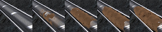
As production continues over time, the annulus between screen and casing tends to bridge with sand, which increases flow resistance. Eventually, the annular space can become completely bridged, halting flow, and a differential pressure forms between the wellbore and the production string, Fig. 3. At this point, fluids can no longer flow to the ESP, and the completion string must be pulled. Depending on multiple variables related to solids production, the duration of time it takes to halt flow via a solids bridge over the screens may be less than the mean time between failure of allowing the ESP to pump the solids-laden fluid to surface, and so a second-generation assembly was developed.
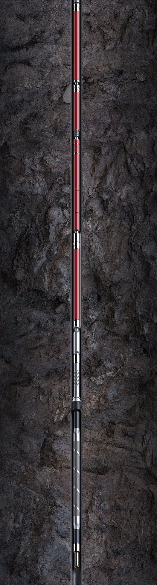
Second-generation pump protection assembly. The PumpGuard* intake sand control screen and valve assembly system is suspended beneath a REDA* pump in Fig. 4, in an example of an unconventional ESP well completion. Once the well produces, the screen filters the solids from production but will begin to slowly bridge with sand, and a differential pressure forms. When this differential pressure reaches the set cracking pressure of the valve, the valve opens, which allows fluid to flow directly into the string toward the ESP. This flow causes the differential pressure across the screen to equalize, thereby loosening the grip of the sand pack on the outside of the screen. Sand becomes free to slough out of the annular space, which reduces the flow resistance through the screen and allows flow to resume. As the differential pressure drops, the valve returns to its closed position, and the normal flow scenario is resumed. This cycle repeats until it becomes necessary to pull the ESP out of hole for servicing. The case studies highlighted in this article have proven this system capable of significantly increasing pump life, compared to running the screen completion alone.
For recent installations, a cost-driven solution for zonal isolation between the stainless-steel wool screen and ESP was introduced. A downward-facing cup-style packer was installed above the screen section. Above the cup packer, additional basepipe perforations provide a flow path for produced fluid to migrate from inside the screen to the annular space above the packer, where the fluid can enter the ESP intake.
The stainless-steel wool screen filters selected for this solution provide several benefits over a gap-based, 2D screen type. The 2D filters rely mainly on particles bridging across the gaps, or slots, in the filter to build a sand pack and enable sand control. However, as only a single value for the gap can be chosen for a screen, the screens become highly sensitive to the particle size distribution of the produced fluids.
Conversely, the thick mesh bed of the stainless-steel wool screen filter provides a high porosity (92%) and large open flow area (40%) for produced wellbore fluids. The filter is constructed by compressing and directly wrapping a stainless-steel wool mesh around a perforated basepipe and then encapsulating it within a protective perforated shroud that is welded to the basepipe at each end. Distributed, nonuniform angular orientation of the pores within the mesh bed (which vary from 15 µm to 600 µm) allow harmless fines to flow along 3D flow paths toward the basepipe after the larger and harmful particles have been trapped within the mesh. Sand retention testing on this screen’s coupons has proven the filter maintains a high permeability, as fluids are produced through the mesh. Effectively, this single “gauge” of filter can handle all particle size distribution of produced fluids encountered. This stainless-steel wool screen was developed in the 1980s by a supermajor operator specifically for standalone screen completions in steam-stimulated reservoirs and has an extensive track record of successful installations.
The valve assembly is composed of a spring-loaded valve that permits one-way flow from the production zone into the tubing string. By adjusting the coil spring preload force prior to installation, the valve can be tailored to achieve the desired cracking pressure for the application. Typically, a single valve is run below the stainless-steel wool screen to provide the secondary flow path between reservoir and ESP. In some cases, multiple valves and stainless-steel wool screens are run in series, in which the middle valve(s) are set to lower cracking pressures than the lowermost valve.
Over time, formation particles fill the annular area between the outer surface of the pump protector assembly screen and the production casing wall. As the cavity fills with sand and the particles consolidate, the pressure drop across the sand pack increases. When this pressure drop reaches the preset value, the cone valve opens and allows flow directly through the pump intake. At this stage, the flow through the tubing enables unpacking the previously consolidated sand particles along the exterior of the screen filter. Flow will resume through the screen, and the intake valve will close, due to reduction in differential pressure. Therefore, the pump sees flow directly from the valve for only a short while. This causes an increase in pump life, as most of the flow is filtered fluid through sand screen.
FIELD TRIALS
The pump protection system, in conjunction with a cup packer, was run in three different wells in the U.S. Delaware basin. The primary objectives were to reduce the number of ESP starts and stops, due to sand-related overload and to enhance ESP availability for production improvement. The pump protection system was hung from the lower end of the ESP string. The results from the wells showed stable pump behavior, with reduced vibrations and amperage, with pump protection technology. After installation of the new system, the number of shutdowns related to sand and solids was reduced by as much as 75%, with over 22% extension of pump life.
Well A. An ESP system was installed in a newly drilled and fractured well in Martin County, Texas. The vertical section of the well is about 9,000 ft, and the horizontal section extends to 12,000 ft, measured depth (MD). For the initial two completions, a downhole vortex-induced sand separator system with six joints of tailpipe was installed as an integral part of the ESP completion. Erratic behavior of the ESP operating parameters (amperage and vibration) was observed for both consecutive installations with the same type of sand separator. The teardown analysis of the pulled ESP equipment showed that the vortex gas separator assembly was plugged with foreign material, which was identified as sand, since it was nonmagnetic and did not chemically react to acid.
On the third ESP installation, a stainless-steel wool screen replaced the sand separator as a means of ESP sand control. After installing the new pump protection system, the ESP displayed more stable behavior, reducing the range of fluctuations in motor amperage from ~19 A in install #2 to ~6.3 A in install #3. Vibrations were more stable, with 75% reduction in the trend. Drawdown was also stable, displaying little fluctuation compared to the previous installation and gaining an additional 100 psi of drawdown. ESP overload shutdowns were reduced 100%, with the ESP operating at low vibration.
Well B. In a well near Eunice, New Mexico, another unconventional well had an ESP installed with no pump protection. After the drawdown from the initial startup, the ESP began displaying erratic behavior. The swings in amperage and pressure correlated with a spike in vibration. After sustaining these conditions for 137 days, the ESP failed, and a replacement was installed. The second installation included the new pump protection system with same ESP configuration. After the well was returned to production, the ESP behaved normally with stable amperage and lower vibration. At the time of publication, the ESP second run had achieved over 300 run days, a significant improvement compared to the previous installation.
Well C. The third field installation of the system was in Mentone, Texas, by an oil and gas major that had been experiencing disruptions and ESP failures, due to sand production and wanted to improve pump uptime. The operator typically ran a downhole sand separator with the tailpipe in every ESP well. However, once the tailpipe gets filled with sand, the separator allows the sand to flow through to the pump section, eroding the pump stages, bearings, and shaft, and resulting in loss of lift. After running the new system with the pump protector, ESP run life was extended by 22%, with more stable drawdown and better ESP-related uptime.
The number of shutdowns related to sand and solids while running was reduced by 75%, from eight overload events in the first install to two events in the second install, and the number of successful restarts after an overload shutdown was improved by 30%, from 12 events to a total of eight in the second install, reducing electrical stress on the equipment and improving run life of the ESP.
VALUE DELIVERED
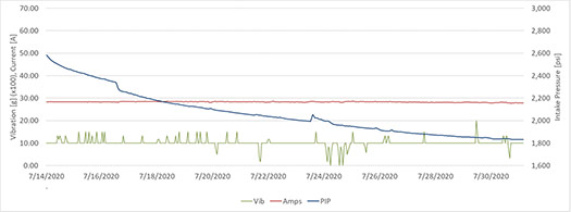
Figure 5 shows the intake pressure signature (blue) rises suddenly when the stainless-steel wool screen is plugged, and the valve assembly opens. This pressure signature enables further improvements in production efficiency by predicting the impeding sand-related ESP failure, so replacement operations using workover rigs can be planned.
*Mark of Schlumberger
REFERENCE
1 Martins, J. A., E.S. Rosa, S. Robson, “Experimental analysis of swirl tubes as downhole desander device,” SPE paper 94673-MS, presented at the SPE Latin American and Caribbean Petroleum Engineering Conference, Rio de Janeiro, Brazil, June 20–23, 2005. https://doi.org/10.2118/94673-MS.
ACKNOWLEDGEMENT
This article contains elements from SPE paper 207926-MS, presented at the Abu Dhabi International Petroleum Exhibition & Conference, held in Abu Dhabi, UAE, Nov. 15–18, 2021.


- Simplified intelligent completion architectures improve zonal control economics (May)
- From post-mortem to real-time: A scalable approach to fracture diagnostics (May)
- The value of all-electric intelligent completions (April)
- The benefits of Simulfracs (January)
- Molecular fracing: A rock-focused, field-ready stimulation chemistry (January)
- Halliburton’s ZEUS IQ™ powers the first fully autonomous fracturing platform with closed-loop automation (January)
- Subsea technology- Corrosion monitoring: From failure to success (February 2024)
- Applying ultra-deep LWD resistivity technology successfully in a SAGD operation (May 2019)
- Adoption of wireless intelligent completions advances (May 2019)
- Majors double down as takeaway crunch eases (April 2019)
- What’s new in well logging and formation evaluation (April 2019)
- Qualification of a 20,000-psi subsea BOP: A collaborative approach (February 2019)

