New implementation of relief well technology reduces risks
For many years, relief wells were viewed as the solution of last resort—only to be used when all other strategies failed or were clearly unsuitable. As experience was gained, and directional drilling capabilities evolved and “ranging” techniques improved, relief wells gained acceptance as a highly dependable solution. This perception of dependability moved the relief well from a solution of last resort to a primary solution in many cases.
Most people's concept of a relief well operation involves drilling a new well into an existing well that is blowing out—often accompanied by high-rate, dynamic kill operations. These operations still take place, but the techniques that have evolved from years of relief well drilling have led to another use for high-precision intercept wells: the Intervention Well (IW). IWs use similar technology, in terms of magnetic ranging and well placement, but their purpose is to align with and typically penetrate a well that is not blowing out, usually for the purposes of isolating potential flow sources. This enables the de-risking of planned surface operations and enhancement of previous plug and abandonment (P&A) efforts, where well access is not possible or practical.
The ability to use an IW to enhance poorly implemented or questionable P&A operations has become increasingly valuable, as operators move toward using old producing oil fields for carbon capture and sequestration (CCS).
Evolution of relief wells. Relief wells have been employed for decades to resolve well control events. Prior to the advent of borehole surveying instruments, wells were drilled vertically near a blowing well and then used to "relieve" the reservoir pressure by allowing the relief well to flow at high rates. Most people generally agree that the first modern relief well was drilled near Conroe, Texas, in 1933. That well initiated a period where relief wells would be directionally drilled into the reservoir much closer to the blowout. Water and kill mud would then be pumped into the blowout reservoir to actually kill the blowout. This type of relief well strategy remained standard practice until the 1970s.
By 1970, wireline-conveyed instruments were used to detect the blowout well tubulars and guide the relief well to the first direct intercept (perforation between wells).1 By the mid-1970s, methods were developed to guide relief wells, using Passive Magnetic Ranging (PMR). This approach measured the perturbations in the Earth's magnetic field, caused by the remnant magnetic poles on the blowout casing or drillstring. The predecessor of modern relief well guidance technology was developed around 1980. This system is called Active Magnetic Ranging (AMR), and it works by analyzing a magnetic field that is induced by injecting an AC current through the sediment from the relief well onto the target well.
AMR, often used in conjunction with improved PMR methods, is used to guide modern relief wells. These tools, along with improvement in measurement-while-drilling (MWD) and wellbore surveying, led to direct intercept relief wells, where the relief well actually makes controlled contact with the blowout well, and a hole is milled into the blowout well casing. This greatly improved implementation of dynamic kill operations, since the flow path for kill fluids was no longer through the producing formation or perforations.
The latest milestone in relief well drilling is the ability to align with the relief well, with sufficient precision to mill a window in the target well casing, which allows re-entry with small tubing strings. This version of the relief well can be used to implement zonal isolation through placement of additional cement plugs.
Work is ongoing to broaden the use of these high-precision wells, by devising ways to conduct operations below the intercept window (milling, fishing, running downhole tools, etc.) and milling entire sections of casing, to facilitate placing a rock-to-rock isolation plug.
Reducing safety risks. The industry is plagued with old wellbores and wellheads that are in poor condition. Sometimes these wellbores and/or wellheads pose serious safety risks that make it difficult for even specialized intervention. Many of these wells have a single barrier that may be of questionable integrity, and disturbing it may lead to an uncontrollable situation. It is most often the lack of shallow wellbore pressure integrity that drives the solution toward isolating the pressure source(s) at the bottom of the well—or at least deep enough to re-establish caprock integrity. The goal of the IW in this instance is to reduce the safety risk from an uncontrolled blowout down to managing trapped pressure below the existing barrier.
Reducing operational risk. As the number of P&A wells increases, there’s a corresponding number of instances where previous P&As are coming under escalated scrutiny. Some of these instances are due to minor leaks or soil disturbances observed around previous wellbores, while for others, it may be a result of the due diligence associated with acquisitions. One recent development is the review of previous P&As related to CCS.
Logically, the best candidates for CCS are often older, depleted reservoirs. However, almost all these reservoirs were exploited using numerous wellbores. Once the productive zones were depleted, the wells were permanently abandoned. Unfortunately, some of the permanent P&As were not done in accordance with best practices, or there are no records to confirm that adequate, long-term isolation was established and verified. Many wells were left with wellheads removed and shallow cement plugs set. In cases where wellhead access is either impossible or cost-prohibitive, an IW may be an ideal choice to verify or enhance zonal isolation.
If the need to confirm or enhance zonal isolation is identified, the decision process is relatively simple, if the well is easily accessible. A direct intervention can be performed, even if a tie-back and new wellhead installation is required. However, if the well is not easily accessible—such as offshore with the wellhead removed below mud line, or a land well with casings removed or damaged below a depth where excavation is practical—then the decision process should include an IW as a solution.
Numerous successful excavations have been carried out, both on land and in offshore environments. However, these operations involve substantial operational risk that can sometimes be avoided with an IW. Costly and time-consuming excavations followed by well tie-backs almost always pose the risk of operational difficulties during the actual re-entry. Years of corrosion, unknown blockages and unforeseen downhole damage could make the P&A intervention unsuccessful. A thorough operational risk assessment should be carried out, any time there is a distinct possibility of downhole problems. The risks identified with direct re-entry should be assessed, relative to those involved with using an IW to establish the required isolation.
It should be noted that the ability to conduct P&A operations will almost always be better with a conventional well re-entry than it will be with an IW. Direct re-entry allows the use of conventional tools for diagnostics, cement placement, utilization of full-bore plugs and packers and the ability to confirm plug placement, through application of weight and pressure testing.
Example 1. A new well was drilled on an offshore platform that already contained numerous other wellbores. There was an obstruction encountered immediately upon drilling below the 30-in. conductor. It was believed at the time that the obstruction was caused by a deformation near the bottom of the conductor. Under that belief, the solution was to use a mill to clear the conductor. After extensive milling, it was discovered that the obstruction was actually an adjacent well. Milling operations had penetrated into the adjacent well and severed the 4 ½" production tubing just above the Surface Controlled Subsurface Safety Valve (SCSSV). The adjacent, damaged well could produce several hundred barrels of oil per day, with significant volumes of gas containing high concentrations of H2S.
When the real situation was discovered, options for securing the damaged well were investigated. Once the extent of the damage was fully known, it became obvious that intervening directly on the well involved intolerable risks. If the SCSSV or the tubing below it was disturbed, there would be no chance of containing the surface pressure, and a blowout would surely result.
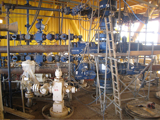
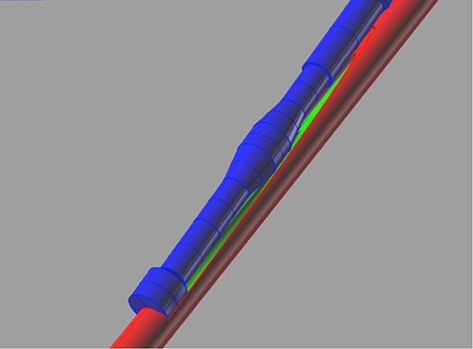
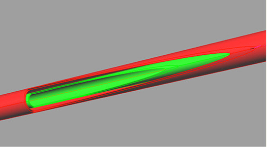
The chosen solution was to install a very large diverter assembly (Fig. 1), with four overboard lines made up of 13 ⅜-in. casing, then drill an IW to isolate the reservoir. The IW was drilled successfully, using a semisubmersible rig that was positioned nearby but had to overcome serious collision avoidance issues in the crowded well environment. Penetration of the damaged well was made at approximately 8,000 ft, TVD. A window was milled in the 7 ⅝-in. production casing and 4 ½-in. production liner (Figs. 2 and 3), which allowed a 2 ⅜-in. cementing string to be introduced into the well. A 1,200-ft cement plug was placed across the perforated section, which was later tested, using a well test arrangement that allowed an underbalance to be created above the plug. Surface intervention operations were then initiated to fully abandon the damaged well.
Example 2. In another instance, an offshore well was scheduled to be plugged and abandoned. At the beginning of the rig operations, it was discovered that the production tubing was parted at a very shallow depth, and there was no wellbore pressure integrity. Fluid pumped into the tubing from the top of the production tree was seen exiting from the conductor x surface casing annulus. Meanwhile, the SCSSV was thought to be containing reservoir pressure at values approaching 7,000 psi. Several direct intervention options were discussed, including removal of the parted tubing and tie-back, using high-pressure pack-off overshot. Ultimately, the decision was made that direct intervention was too risky without first isolating the reservoir.
A diverter assembly was installed on the target well, and the IW drilling commenced from a JU rig. The IW, though challenging, was drilled without significant problems, and an intercept was made above the production packer, Fig. 3. As soon as the production casing was penetrated, flow was observed at the target well platform, as seawater was displaced by drilling mud. The well was stabilized, and then the production tubing was penetrated. The lack of additional flow at the target well confirmed the integrity of the target well tubing.
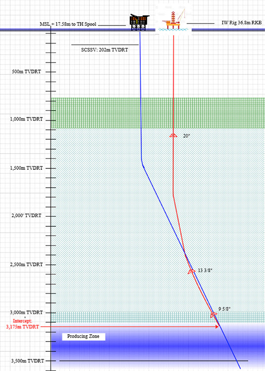
Since the well had a downhole tubing hanger near the surface, the parted tubing did not drop into the well. This made it possible to create a window through the production casing and the 4 ½-in. tubing, then introduce a 2 ⅜-in. tubing string. A cement plug was placed across the perforations and into the tubing above the packer. The production tubing was then perforated, and an annular cement plug was circulated into place to enhance isolation, Fig. 4.
Planning and implementation. Recognition of the growing importance of IWs is encouraging an increase in suppliers providing support for such operations. However, when developing a plan for an effective intervention well, it is important to consider engaging with an experienced well control provider. An IW cannot be regarded merely as just another high-precision directional well. In many instances, there are underlying well control risks associated with an aging well that require a fully rounded plan from a well control company. Failing to recognize the different requirements of an IW versus a standard, high-precision directional well can exacerbate existing on-site problems.
Engineering, management and design services will be required to ensure proper and comprehensive planning and oversight for the safe and successful execution of the intervention well plan. Project planning will involve the supervision of drilling, testing and completion operations. This will include managing the operator and service company’s non-routine technical support personnel. It will also involve the coordinated management of personnel and equipment for directional drilling and MWD, borehole surveying, homing in (electromagnetic ranging), and wireline and milling and perforating.
Effective and accurate intersection management planning will also be critical. This should include:
- Well surface location selection
- Target well and intervention well position uncertainty derivation
- Ranging strategy (active, passive, and other methods)
- Intersection strategy
- Hydraulic communication and kill strategy
- P&A execution and verification
A window into the future. An evolution from relief wells, intervention wells are increasingly becoming recognized as an effective solution in reducing the operational and safety risks associated with intervening on aging wells. Intervention wells can be deployed to effectively de-risk planned surface operations and enhance P&A, where direct well access is no longer possible. Alongside the benefits of new or improved P&A, intervention wells also allow the verification of zonal isolation, and they can be an active enabler in the development of sites for carbon capture and sequestration. WO
REFERENCES
- Wright, LW and Flak, L; Advancements in technology and application engineering make the relief well a more practical blowout control option


