Detecting and recovering oil from flowback and produced water
Flowback and produced water from horizontally drilled and completed wells in shale formations contain significant amounts of valuable oil that can be recovered and sold. Commercial saltwater disposal (SWD) facilities count on the additional revenue from “skim oil” to make their facilities profitable. However, producers are eager to put that lost oil in their sales tanks, rather than sending it to the SWD. But a facility investment decision based on oil recovery is difficult to impossible, without knowing how much oil is in the water.
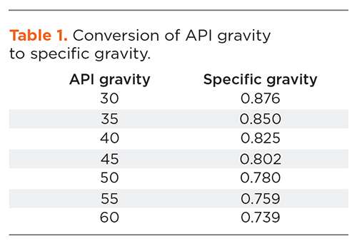
Determining oil-in-water concentration. The concentration of oil in water is reported in either milligrams per liter (mg/l) or in parts per million (ppm). The ppm reading is usually on a weight basis (ppW) and is the same as the mg/l reading. It also can be reported as a volumetric measurement (ppmV) which, can be turned into useful financial information in terms of barrels (bbl) of oil, where 1 ppmV is 1 bbl of oil in 1 million bbl of water. A concentration in mg/l (ppmW) can be converted to ppmv by dividing by the standard specific gravity of the oil. Oil is bought and sold based on its API gravity, which is easily converted to standard specific gravity (SG) with the formula SG = (131.5 + API) / 141.5. Table 1 shows a conversion of API gravity to specific gravity. An API 55° shale oil has a specific gravity at standard conditions of 0.759, so 1 mg/l(ppmW)/0.759 is equal to 1.32 ppmV, or 1.32 bbl of oil per 1 million bbl of water.
A typical production separator may discharge water with 1,000 mg/l of oil, which is equal to 13.2 bbl of oil in 10,000 bbl of water. If the same water is sent to an SWD facility, the SWD will recover some of the oil and pump water, with about 100 mg/l into the disposal well or approximately 1.3 bbl of oil for 10,000 bbl of water, leaving the SWD a net recovery of 11.9 bbl of oil for every 10,000 bbl of water processed. Measuring the oil-in-water concentration is the only way the producer or the SWD operator can know how much oil the facility is recovering or leaving behind.
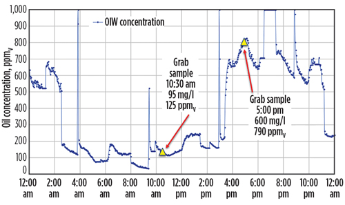
Most producers and SWD facilities that are operating in the shale plays rely on grab samples and laboratory analysis to get oil-in-water concentration data, but real concentration values are constantly changing. Figure 1 shows continuous online oil-in-water data from the suction of an SWD pump, with grab samples at different times showing dramatically different readings. Armed with only data from the first sample, the facility operator may think the facility is operating well, while the lost oil is lost revenue and may cause injectivity problems that drive up cost. Alternatively, if the operator only used the data from the second sample, it may overspend on facility improvements on the assumption that recovery of an additional 7-8 bbl in 10,000 is possible. Traditional lab methods for measuring oil-in-water concentration include the following:
- Taking the sample
- Delivering the sample to a lab
- Extracting the oil from the water using a solvent, such as hexane
- Evaporating the solvent
- Weighing the residual oil that is
not evaporated - Calculating the original oil-in-water concentration from residual oil extracted by the hexane.
These steps are time-consuming, expensive, and prone to errors, due to the many steps involved. An alternate and widely accepted method of quantifying oil-in-water concentration uses ultraviolet (UV) light, which causes oil droplets to fluoresce.
A new kind of oil-in-water monitoring service. A new oil-in-water monitoring system from National Oilwell Varco (NOV) uses UV light to see oil droplets in water. The amount of fluorescent light that is given off by the oil can be measured, and that light measurement is converted into concentration of oil in water. Fluorescence-based oil-in-water monitors have been commercially available for many years, but existing models are expensive and require continuous maintenance and recalibration. In addition, specialized skills are needed to ensure data quality. NOV has introduced a new oil-in-water monitoring service that will eliminate the risk and guesswork of owning a monitor. The service delivers continuous online oil-in-water concentration data to a computer, phone, or tablet, which is combined with data storage, trending and analysis tools to ensure that proper action is taken, based on the information obtained.
Additional process transmitters, such as tank levels and flow meters, can be added to expand the usefulness of the continuous data. For example, a flow measurement added to the concentration data allows the operator to quantify the oil that is going with the water over time, meaning a dollar value for that oil can be established. A tank level combined with concentration data helps minimize oil loss by providing insight into how tank levels affect the oil-in-water concentration.
Continuous oil-in-water monitoring can be applied at the water discharge of a production facility and at the disposal pump of an SWD. Putting a monitor at these locations will allow detection and quantification of lost oil. Additional monitoring points at the truck offload and pipeline connections of an SWD will show how much oil is entering the facility, and monitoring the outlet of the gun barrel can help diagnose and improve oil separation performance. At a production facility, additional monitoring at the separators and heater treaters will help diagnose and optimize separation performance, while monitoring the water from a test separator can improve the accuracy of well tests and help with lease allocations. A monitoring point at the discharge of a frac water recycling facility can be used to divert water back that does not meet the oil concentration requirements and help protect the frac job.
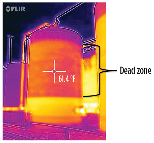
Horizontal gun barrel design. An infrared image of a traditional vertical gun barrel highlights the issues with recovery, Fig. 2. Warmer spots are white and yellow, while cooler areas are darker and trend toward the violet end of the spectrum. The warm areas of the tank show where water is flowing, and the cooler areas are more stagnant and show that the fluids have been in place long enough to cool down. A traditional gun barrel is a vertical tank operated at a constant level. Water enters at the top of the tank, and an internal pipe directs the water down into the tank and through a spreader plate, located about 5 ft to 7 ft above the bottom of the tank. Oil rises above the spreader plate and is skimmed from the top, while water exits a connection at the bottom on the right side of the tank.
For years, gun barrel and tank-based produced water handling systems have been sized on the concept of retention time, but standard calculations assume that the complete tank volume is used for separation. As evident in Fig. 2, only a small portion of this gun barrel is being utilized for separation. NOV introduced the horizontal gun barrel (HGB) to address the issues of poor oil recovery and sand accumulation in conventional gun barrel facilities. A single HGB that is 8 ft × 35 ft can handle 20,000 bwpd. It takes six traditional 1,000-bbl vertical gun barrels to achieve the oil removal performance of one HGB. An HGB facility has a smaller footprint with less piping and a lower total capital cost than a traditional gun barrel system.
Integrating Tore online vessel de-sanding (OVD) technology into the HGB eliminates the concern with solids accumulation. Water enters the swirl chamber, while sand is drawn to the Tore unit and fluidized by a powerful vortex that exits the Tore foot. A single OVD unit will transport about four tons of solids per hr at a concentration of 40% by volume and a modest flowrate of 18 gpm. The horizontal gun barrel has four Tore units manifolded together that effectively remove accumulated sand with about 10 min. of daily operation. The OVD technology removes accumulated solids without shutting down or disrupting the oil recovery process inside the HGB, helping the operator avoid costly tank cleanouts, maximize oil recovery, and lower operating costs.
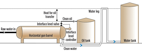
The operating principlel of the HGB is simple. The vessel is horizontal and liquid-packed, meaning there is no gas phase at the top. By flowing water through an inlet baffle plate and across the vessel, the total volume is used for separation. The distance that the oil must travel to reach the oil pad at the top of the HGB is much shorter, so more of the smaller, slower-rising oil droplets are collected. A thin oil pad is maintained at the top of the HGB, which aids in basic sediment and water removal prior to discharge. Figure 3 shows how water and oil flow through an HGB-based system. Water enters the HGB from a pipeline connection, truck offload station, or a free water knockout and exits through a water leg. The water leg maintains a constant head pressure, which keeps the HGB filled with liquid. As oil collects in the HGB, the oil pad grows, and the oil-water interface drops. An interface level controller detects the oil water interface and opens a valve at the top of the HGB. The difference in head pressure between the tall water leg and the shorter oil tank drives clean oil from the HGB to the oil sales tank.
An integrated solution: dynamic oil recovery. NOV’s WaterWolf dynamic oil recovery system combines de-oiling and de-sanding hydrocyclones with the non-shearing action of progressing cavity pumps to achieve residual oil levels below 50 ppm and removal of sand down to 10 microns, Fig. 4. The system recovers oil and produces high-quality water without chemicals or filters. Recovered oil is discharged under pressure and can be returned directly to a gun barrel, heater treater, or freewater knockout without additional collection pits or tanks. Since the oil and solids are removed in separate hydrocyclone vessels, the oil is free of solids, and the solids are free of oil.
The de-sanding hydrocyclone contains high-efficiency ceramic solid-liquid cyclones that will remove solid particles from water at 10 to 15 microns, with the ability to take in solid concentrations exceeding 1% by volume. The solids accumulate in the lower chamber of the vessel, while water exits the top. The solids are occasionally purged from the accumulator as a slurry. The de-sander eliminates the need for most filters and the associated manpower and cost of replacement filters and filter disposal. The de-oiling hydrocyclone follows the de-sander. It contains high-efficiency, liquid-liquid de-oiling hydrocyclones that can handle up to 2,000 ppm of oil in the inlet while reducing oil concentration to below 50 ppm without chemical flocculation. The current WaterWolf product line includes three standard models, with capacities of 8,000, 16,000 and 50,000 bwpd.
OPERATOR VALUE ADDED
The water midstream sector has grown in size and complexity over the past few years. Oil-in-water monitoring along the many pipeline connections can identify the producers that are sending oil-rich water into the network, which could lead to more competitive fee structures that compensate operators for oil they send into the system. NOV can design and supply a complete SWD facility that is completely integrated with oil-in-water monitoring technology, backed by the proven HGB process to maximize recovery rates and increase per-bbl profits, as selling pipeline-grade oil can be priced higher than the typical wet oil that is produced at most SWD facilities.
Related Articles- What's new in production: Lighten up (June)
- Executive Viewpoint: Why produced water filtration needs a rethink (June)
- Shifting from calendar to usage-based maintenance: Proven results that demand your attention (June)
- First Oil: Renewed enthusiasm exuded in Canada and within IPAA (June)
- Produced water: How did we get here? (May)
- What's new in production: When everything is going wrong at the same time (April)
- Subsea technology- Corrosion monitoring: From failure to success (February 2024)
- Applying ultra-deep LWD resistivity technology successfully in a SAGD operation (May 2019)
- Adoption of wireless intelligent completions advances (May 2019)
- Majors double down as takeaway crunch eases (April 2019)
- What’s new in well logging and formation evaluation (April 2019)
- Qualification of a 20,000-psi subsea BOP: A collaborative approach (February 2019)

