What’s new in artificial lift?
In last month’s issue, we highlighted several innovations regarding beam/rod pumping, linear lift pumps, and a unique lifetime lift system. This month, we wrap up this two-part series with recent developments in ESPs, PCPs, plunger lift and gas lift systems.
ESP DEVELOPMENTS
An ESP downhole assembly will typically include the electric submersible pump (ESP), a gas handler/separator or standard intake, a seal section, a submersible motor with a connected power cable that runs to the surface, and, often, a downhole sensor package that communicates pump and wellbore performance information back to a surface interface system. The surface equipment may include a variable frequency drive (VFD) or switchboard, a motor protection system and/or an intelligent control system designed for applications that require advanced system control and monitoring.
ESPs are multi-stage centrifugal pumps. These pumps consist of rotating impellers and stationary diffusers that can be stacked in either floater or compression configurations, depending on performance requirements. Upon entering the pump intake, well fluids are subjected to large centrifugal forces caused by the high rotational speed of the impeller. The fluids lose their kinetic energy in the diffuser, where a conversion of kinetic to pressure energy takes place, with each impeller adding more head or pressure to the fluid. More impellers, therefore, are required for deeper wells.
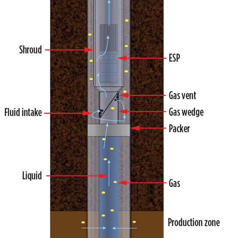
Gas Wedge eliminates free gas through the ESP. Production Tool Solution’s (PTS) new Gas Wedge is designed to prevent free gas from entering the intake of an ESP. The tool juxtaposes shroud technology with an engineered flow tube that utilizes deviant vectors to break gas out of solution, Fig. 1.
Run below a submersible pump, the Gas Wedge increases the velocity of the produced fluid and gas along the deviant vector, then immediately through a series of annular vented ports that provide a pressure drop to burst the gas out of solution. Consequently, the free gas will continue up the annulus, while the fluid will fall along the outside of the wedge. At the lower end of the Gas Wedge, there is a set of intake ports that will receive the gas-free fluid and let it progress up to the pump. The top of the tool is then tied to an inverted PTS shroud system that allows the gas-free fluid to travel alongside the motor and into the intake of the pump for conventional production. At the top of the inverted shroud, there is a secondary point for fluid entry into the ESP, designed similarly to conventional inverted shrouds.
The Gas Wedge eliminates free gas from entering the pump, thereby ensuring optimal run life with maximum drawdown. Additionally, it eliminates the need for an ESP recirculation system used to cool the motor, thereby eliminating a common failure mechanism while simultaneously reducing the cost of the completion.
Liquid concentrating intake reduces gas entrance to an ESP. The Mingo patent-pending Ninja is a liquid concentrating intake (LCI) designed to reduce gas entrance, as well as provide an artificial sump within an ESP tool string. Additionally, internal rotating components further limit the effects of free gas in the intake. HVOF tungsten carbide coating, applied to the tool’s internal mechanisms, reduces erosion and abrasive wear, extending run life. An elongated sump design provides liquid rich sump allowing “ride through” during a slug event.
Case studies in gassy low-volume wells have illustrated the Ninja’s potential for improving ESP performance and increasing production volumes, primarily through the elimination of gas locking. Ninja intakes also have been installed on several larger volume pumps, with the goal of extending pump run life by improved flow conditioning.
Recently, a Ninja intake was installed with an SF2250 pump upon initial completion of one well. A neighboring well had an SF2250 installed with no Ninja. The goal of the trial was to determine if the Ninja would choke production at high volumes, and if it would extend ESP run life as production declined and GOR increased. No reduction in produced flow was observed in the well with the Ninja, eliminating any concerns of a system choke. The well without the Ninja failed after 136 days, while the well with the Ninja continues to run smoothly. While these higher-volume trials continue, performance data suggest that the Ninja successfully conditions flow at higher flowrates and lowers the GLR of fluid entering the ESP by the liquid concentrating mechanism.
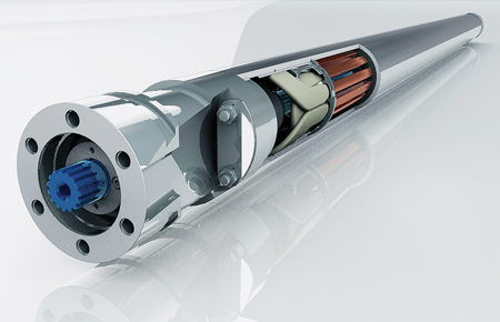
New PMM for ESPs. Baker Hughes, a GE company (BHGE) has added the Magnefficient permanent magnet motor (PMM) to its ESP portfolio, Fig. 2. Focused on lower lifting costs, operators are looking for new ways to increase ESP system efficiency. One way to achieve this is by reducing energy consumption, considering traditional ESP motor energy consumption accounts for up to 30% of ESP system efficiency losses. This is critical in declining, mature fields, where operators are challenged to improve or maintain economics, or areas where operators are penalized/rewarded, based on their power usage.
According to BHGE, their new PMM significantly improves efficiency by lowering ESP system energy consumption, allowing operators to do more with less. The motor eliminates induction losses, lowering system power consumption 20% and reducing motor power loss 50%. And, with lower idle amps, the PMM enables better control at lower loads than traditional induction motors. It also delivers a higher power density, enabling operators to achieve a higher horsepower with the same motor, or the same horsepower with a smaller motor.
With more power per length, operators are able to eliminate the need for tandem connections, which improves reliability and allows for quicker installation, saving additional time and cost. This also allows the ESP system to be placed deeper in the well, closer to producing zones for maximum production in deviated wellbores. Additionally, the PMM maintains a more constant power factor and efficiency over a larger load range, compared to induction motor technology. This helps reduce cable power losses, or when applicable, allows the operator to use a smaller cable to save additional costs.
While the efficiency gains of this new technology are impressive, it is not possible to deliver successful results without ensuring the highest level of reliability. BHGE leveraged learnings from other GE businesses to develop the Magnefficient PMM, including GE Aviation for the rotor design, and GE Healthcare for magnet research. The R&D team used advanced optimization algorithms to evaluate the design, based on efficiency, power factor and power density, while making sure those design elements did not violate temperature limits, rotor dynamics stability or material structural capabilities. The PMM shares many of the same basic components as BHGE’s induction motors, to sustain the same level of quality and reliability.
The Magnefficient PMM already has delivered positive results in the field, with ongoing applications in both Latin America and North America.
Improved power quality extends ESP runlife. Root Cause Failure Analysis (RCFA) and Power Quality (PQ) studies contribute greatly to an increased understanding of how poor PQ reduces the run life of ESP systems. Various and ongoing studies have identified the presence of damaging high-frequency (HF) harmonic content associated with VFD operation. HF harmonics are known and significant culprits in the breakdown of insulation and rotor bearing fluting. By understanding and avoiding the most common failure modes, especially as they relate to ESPs on VFDs, ESP system run life can be extended.
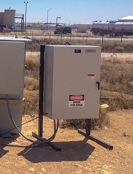
In 2017, Magney Grande Distribution, Inc. introduced the Common Mode Filter (CMF) (see World Oil, June 2017), Fig. 3. The product was developed for producers who asked, “Why do ESPs last longer with switchboards than with VFDs”? To date, Magney Grande has successfully installed 500+ CMF units to oil fields utilizing VFDs to operate ESP wells. A marked decrease in ESP system failures has occurred.
The CMF is applied to the medium-voltage (MV) taps on the output side of the Step-Up Transformer (SUT), to improve the quality of the sinewave between the VFD and downhole equipment. The CMF shunts HF current to ground, thereby reducing cable skin-effect heating and virtually eliminating damaging ringwaves. The application of the CMF to ESPs on VFDs has proven successful in greatly reducing damaging HF harmonics and extending equipment run life (including cable, wellhead feedthrough, motor-lead extension/pothead and ESP motors).
The first VFDs were installed in the oil production industry in 1976. Today, thousands of VFDs are employed to oil field sites. Electrical utility providers clearly understand the need to limit harmonic content on a distribution system where multiple VFDs are operating.
IEEE 519-2014 effectively established harmonic distortion limits (voltage and current) at the Point of Common Coupling (PCC). While the IEEE standard is helpful to utility providers, it only applies to the input side. There are no established standards to help a producer limit harmonic content produced by the VFD on the load side, where it matters most to ESP equipment longevity.
Sine Wave Filters (SWFs) are useful for filtering harmonic content on the Normal Mode (Line-to-Line), however they do nothing to reduce or eliminate the damaging HF content, which persists on the Common Mode (Line-to-Ground). The CMF is designed and installed to address this problem.
The U.S. Department of Energy has published that damaging reflected waves are generally not a problem when the distance between the motor and drive is less than 15 ft. In the oil production industry, this distance is often measured in thousands of feet. By dissipating HF content at the surface, the downstream electrical (and mechanical) systems can operate longer without additional heat and electrical stress on components.
PCP DEVELOPMENTS
A progressive cavity pump (PCP) is a type of positive displacement pump. These pumps are also known as eccentric screw pumps or cavity pumps. As the pump’s rotor turns, PCPs transfer fluid through a sequence of small, fixed-shape discrete cavities. This leads to the volumetric flowrate being proportional to the rotation rate (bi-directionally) and to low levels of shearing being applied to the pumped fluid.
The cavities of a PCP taper down toward their ends and overlap with their neighbors so that, in general, no flow pulsing is caused by the arrival of cavities at the outlet, other than that caused by compression of the fluid or pump components.
Depleted wells will have a tendency to produce gas, which can have a negative effect on artificial lift pumping systems. As previously indicated, ESPs often have difficulty handling wide and varying flows and even PCPs, which do not have the gas lock issue that plagues ESPs and have the ability to handle some free gas through the fluid, can be affected when the free gas at the intake pressure exceeds 20%. In addition, when the well architecture features a high dogleg severity, it makes the likelihood of equipment failure very high for rod-driven PCPs.
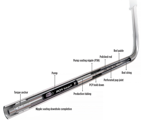
First insert all-metal PCP. PCM has 85 years of PCP expertise and a history of innovative applications engineering. PCM believes, in some cases, it is possible to benefit from two technologies at a time when both are suitable and compatible. In this light, the company has introduced the first insert all-metal PCP (Fig. 4), combining the benefits of two technologies for difficult-to-extract unconventional reserves.
The All-Metal Progressive Cavity Pump (AMPCP) is capable of pumping cold or extremely hot, highly viscous unconventional hydrocarbons and high-temperature water. The insert system allows changing operation in low-production wells at the lowest cost.
With a metal stator replacing the elastomer, the patented PCM Vulcain AMPCP features the same geometry and advantages of a conventional PCP while eliminating rubber temperature limitations. The AMPCP technology is highly versatile, as it is unaffected by transient periods: i.e., SAGD warm-up period, beginning or end of the cycle in cyclic steam stimulation (CSS) or erratic heat front propagation of fluctuation during steam flood production. This makes it a highly attractive artificial lift system and suitable technology to meet the different requirements of all thermal recovery methods. In addition, it remains as simple as a conventional PCP to operate, especially when it comes to adjusting pump speeds to varying flowrate conditions.
The insert PCP is a through-tubing retrievable system, allowing run-in/pull-out of the rotor and stator using only a light pulling unit. This eliminates the need to pull and rerun the production tubing, which greatly reduces downtime and associated costs, as well as eliminating the costs associated with a more expensive workover rig. Changing the pump also can be done easily while keeping in place the downhole gauges and their cable attached to the tubing.
The insert PCP also is an ideal solution for remote wells, where accessability is difficult for workover rigs and/or when workover rigs are not available. Additionally, the system offers a possible back-up option when a primary artificial lift system fails, requiring a long-awaited rig.
The high-temperature AMPCP is targeted for thermal enhanced oil recovery (EOR) involving electro-heating, where the downhole heaters enable the extra-heavy oil to be produced to surface, and where conventional elastomer PCPs fail, due to the high temperatures. The pump can be installed in 4-½-in. tubing at a depth of 2,953 ft (900 m). The production range with this system is 850 to 1,000 bpd.
PLUNGER LIFT DEVELOPMENTS
As an artificial lift method, plunger lift falls into the flow enhancement category. It makes use of a well’s own energy (gas and/or pressure) to lift accumulated fluids from the tubing and annulus. A plunger utilizes an interface seal between fluid in the tubing and stored gas in the annulus. The head gas is blown down, creating differential pressure across the plunger, which pushes both the plunger and accumulated fluid to the surface.
Maintaining production and longevity of the plunger lift system is highly dependent upon how the mechanical components interact in the wellbore. Plunger lifts are commonly used to remove liquids from gas wells or produce relatively low-volume, high-GOR oil wells.
Surface treatment extends life of plunger lift equipment. Mechanical wear, corrosion and abrasion are common production challenges that customers face during field operations. These production challenges have a significant impact on the longevity of equipment, resulting in increased operating expense tied to equipment replacement, well interventions, and lost production due to downtime.
To address these challenges, Endurance Lift Solutions (ELS), through a joint venture owned by its parent company (Synergy Energy Holdings), utilizes artificial lift equipment that features an advanced metal surface treatment technology called BLAZE.
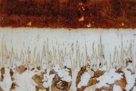
BLAZE is a completely new and unique method of Thermal Boron Diffusion (TBD) using a proprietary chemical formula to produce a slick, hard inter-metallic ceramic boride layer on metal surfaces, Fig. 5. In contrast to other surface treatments on the market, such as hard chrome, tungsten carbide thermal spray and bronzing, the new boron diffusion process excels in all aspects, such as:
- Reduced coefficient of friction—permanent lubricity, regardless of load.
- Highly resistant to abrasion—inter-metallic ceramic nature means no risk of bonding breakdown; no increase in brittleness, excellent impact resistance.
- Corrosion resistance-—impervious to fracing acids, H2So4, HCL, Phosphoric, Chlorides, H2S and others.
- The treatment layer is 100% uniform where deposited, regardless of the part configuration (the layer can encapsulate an item or can be applied in select areas only).
- The layer averages 0.005-in. to 0.006-in. deep but will not affect the original dimensions or surface finish of a part (i.e., a surface with a 1-Ra will have a 1-Ra after the treatment).
- The treatment is comprised of a single-phase layer of only Fe2B, which sets it apart from all other types of thermal boron diffusion.
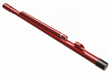
ELS has successfully trialed downhole plunger lift and surface valve equipment treated with BLAZE. The company now offers multiple commercial products, including treated conventional, by-pass and quick-trip plungers and surface valve trim kits in various sizes.
The treated products have demonstrated run life improvements of up to 400% over other protective coatings/surface treatments. These run life improvements have enabled operators to reduce total lease operating expenses, reallocate lease operators’ time in the field to solving other challenges versus conducting routine equipment changes, and decrease their HSE risk, due to fewer well-related interventions.
Given the success of ELS-treated plunger lift equipment, the company is developing a line of BLAZE rod lift equipment, including sucker rod accessories and rod pump components.
GAS LIFT DEVELOPMENTS
Globally, gas lift systems are used in about 30% of oil wells that have insufficient reservoir pressure to produce naturally. The process involves injecting gas through the tubing-casing annulus. Injected gas aerates the fluid to reduce its density; the formation pressure is then able to lift the fluid column and force it up the wellbore. Depending on the well’s producing characteristics, and the specific characteristics of the gas-lift equipment, gas may be injected continuously or intermittently.
New gas lift technology. Widely used for more than 50 years with few notable changes, gas lift has several advantages, especially in the early stages of a well’s production when flowrates are critical for optimized financial returns. Because it’s relatively simple with few moving parts, gas lift is uncomplicated to operate. The method is cost-effective, with few maintenance or repair issues. It can handle sand, produced solids and gas with essentially no problems. With its larger flow area, annular flow gas lift is commonly used for high-rate wells during initial production.
However, as the well’s effective pressure naturally declines, it becomes more efficient to produce hydrocarbons up the tubing with conventional gas lift. Switching gas lift between annular and tubing flow can be costly, typically requiring a workover rig or costly side pocket mandrels. Recently, Liberty Lift developed a new patent-pending technique and HyRate gas-lift mandrel to address and improve this gas lift shortcoming, Fig. 6.
During annular lift, gas lift valves are positioned throughout the tubing string, mounted inside gas lift mandrels. In this configuration, there is insufficient clearance to pull the bottom plug to convert to tubing lift. Consequently, a workover rig is required to remove the entire tubing string and mandrels, in order to switch to conventional tubing flow. This expensive and time-consuming procedure causes deferred production and materially increases the cost to produce the well. A less-intrusive side pocket mandrel configuration is available, but it is substantially more expensive than conventional gas lift mandrels and valves.
Liberty Lift’s HyRate solution facilitates gas lift for both annular and tubing flow without the need for a workover rig. It incorporates an externally-mounted assembly, with special capsule mandrels that allow annular flow, and conventional mandrels permitting conventional tubing flow. The conversion from one lift method to another can be accomplished quickly, and efficiently, with a slickline to pull or replace the bottom tubing plug. Initial operating volumes, ranging from more than 5,000 bpd to as low as 50 bpd, can be handled effectively by this single flexible solution. During later stages, HyRate allows the well to be produced with conventional gas lift for the remainder of its life-cycle, all with a single cost-effective and rigless wireline intervention.
HyRate’s value is multiplied in today’s robust unconventional market, where deviated wells are run from the same pad, incurring frac hits from offset producing wells. Removal of the transient fluids using tubing lift is considerably slower, but HyRate can unload those fluids quickly by seamlessly switching to annular flow, returning the well to optimal production. This ability to continually convert the system from conventional to annular lift, with only a slickline intervention, is cost-effective and efficient. It extends the life of the well and its components.
Intelligent system eliminates gas lift uncertainties. A new Digital Intelligent Artificial Lift (DIAL) gas lift production optimization system, enabling more efficiency with less intervention, plus more data and less uncertainty, has been developed by Silverwell.
DIAL encompasses a fully-qualified, tubing-conveyed, surface-controlled, multi-rate gas lift unit rated to 10,000-psi burst, 6,000-psi collapse and 257°F (125°C). Each unit includes up to six independently actuated orifice valves and onboard pressure and temperature transducers.
The system allows more production from enhanced lift efficiency; less intervention with a reduction in OPEX and risk; more data through the increased insight from multiple in-well sensors; and less uncertainty, with the potential for improved management decisions.
DIAL integrates downhole and surface monitoring/controls in real time. The different-sized orifice valves housed in the in-well units accommodate a wide range of unloading and gas lift production operating conditions. As reservoir conditions change, the injection rate and depth can be adjusted remotely from the surface and confirmed in real-time data.
The system design does not incorporate gas-charged bellows, meaning there is no requirement for a gas charge with no dependence on pressure or temperature, and the gas lift valves are not pressure-sensitive. This means they are much less sensitive to uncertainties in well design variables; there is no requirement to design-in at each unloading valve a pressure differential to avoid multi-pointing and valve chatter, allowing for the deepest possible injection point to be determined. Hence, the system is less prone to flow instability. Furthermore, the injection orifice size can be adjusted without intervention and onboard pressure, temperature and condition monitoring are achieved at all injection points in the completion string.
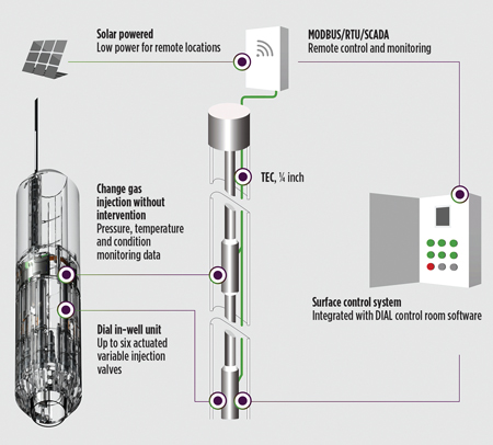
A surface control unit powers and transmits data to and from the DIAL units via industry-standard ¼-in. clamped tubing-encapsulated cable (TEC). The control unit can be configured to support multiple systems in a single well, Fig. 7. The downhole control system assembly is hermetically sealed with electron beam welds to assure life-of-well system reliability, while the gas lift orifice valve assemblies are contained in a 10,000-psi burst-rated housing.
Operation of the system is enabled by Silverwell’s patented Binary Actuation Technology (BAT), which consumes no power until a low-energy control signal is applied. This is instrumental in assuring the 10-year to 20-year design life of the in-well components of the system. Beyond being independently verified by industry-recognized certification bodies, DIAL’s multi-year qualification program results have been accepted by a number of operating companies.
DIAL has been deployed successfully in the Middle East and Southeast Asia, beginning in 2017. In all cases, within days and weeks of installation, the system was being used to optimize lift efficiency without the cost and deferred production of intervention.
New packer enhances gas lift in horizontal wells. Placing mechanically-set production packers in the build section of a gas-lifted well can be a risky operation, usually forcing the running of more-expensive hydraulic-set packers or avoiding packers in the build section altogether. There is good reason to attempt to land the bottom gas lift mandrel as low as possible, to take advantage of additional production drawdown but also to control slug flow tendencies from the horizontal.
Because these types of packer operations are challenging, many operators opt to run the lowermost gas lift valve no deeper than 30° inclination, or even shallower to control retrieval risks. This trade-off reduces the maximum achievable production drawdown. It also means the build section can freely, and violently, release slug flows from the horizontal into the intake of the gas lift system. Consequently, this increases OPEX with greater required gas injection rates and pressures, to achieve gas lift system stability.
HEAL Systems, in a joint venture with Schlumberger, has developed a patent-pending Horizontal Retrieve-Safe Packer (HRSP) that applies the principles of a tension-set production packer with the intent to provide safe landing and retrieving beyond the 30° wellbore inclination. It is engineered for installation and retrieval in horizontals or high wellbore inclinations.
The HRSP incorporates several features to reduce risk:
- Does not require rotation to set or unset.
- Three mutually exclusive release modes (tension shear, compression shear, rotation release).
- Lower pressure rating to improve risk-reducing clearance from the casing during running and retrieving.
- Around-the-bend section, rotationally actuated, mechanically-set packers often run into wellbore frictional challenges that complicate and add risk to setting and un-setting. The HRSP is actuated axially (i.e., up or down with no rotation).
- Right-hand, soft-set release mechanism uses an extended J-mechanism to reduce premature or accidental setting.
- Built with corrosion-resistant metallurgy to withstand harsher downhole environments.
Once the HRSP packer is fully set, it can be left in place like other double-grip and hydraulic packers. It is essentially a tension packer that can anchor itself not only in tension but also in compression, avoiding the need to unnecessarily retrieve the packer during a workover. Conventional tension-set packers are unset by relieving tension. The HRSP packer traps the applied tension, so that the tubing string above can be disconnected without the packer unsetting. Use of carbide button style slips and the sealing element ensures positive casing anchoring in tension and compression to support running subsequent bottomhole assemblies that reconnect to the packer. In the event of a wash-over, and to lower associated risks, there is only one set of slips to mill out.
The HRSP’s greatest safety benefit in gas lifting installation is safe placement beyond 30° inclination. This allows the lowermost gas lift mandrel to be landed deeper in the build section for more production drawdown and more effective slug flow stabilization. Controlling and mitigating slug flows from violently releasing around the build section stabilizes the gas lift system and allows reduced gas injection rates and pressures, ultimately lowering OPEX. ![]()

