Solid expandable technology improves refracture diversion
Solid expandable ReFrac liners are changing the perception of diversion utilized in refracturing operations. Isolating old perforations, and accessing new reservoir rock and reserves, is being done with mechanical diversion, providing confidence that may be unattainable with alternate diversion methods presently available. There had been a perception that solid expandable tubulars are utilized in openhole applications only, or maybe as a stretch, to repair a damaged casing string in a cased-hole application. In reality, solid expandable tubulars are also being used in completion applications—first to enhance present completions utilizing ESeal ReFrac (RF) solid expandable liners, and second to repair completions (new and mature) that have experienced mechanical failure.
SOLID EXPANDABLE RF LINERS
There are two fundamental requirements to effectively refracture a wellbore:
- Must effectively isolate the old perforations.
- Must get the frac fluid/proppant into the new rock (formation).
The results of non-mechanical diversion methods, historically, have fallen short of the first requirement. A majority of the refracturing treatment enters the heel of the wellbore, leaving a large portion of the wellbore un-stimulated.1 Mechanical diversion can meet both the first and second requirements. Unless a solid expandable tubular is used, the ID restriction, when using conventional tubulars or coiled tubing options, prohibits acceptable pumping rates to effectively refracture the new formation.
RF liners are used to mechanically isolate and seal off old perforation intervals, and re-line the wellbore with new casing, providing a “new wellbore,” thus, a means to re-perforate and fracture new reservoir rock in wellbores that were initially completed/fractured some years earlier. Typically, these wells have experienced a significant production decline to an unacceptable economic return. In the present low oil-price environment, drilling a replacement well often will not meet ROI thresholds; however, a recompletion utilizing refracturing techniques can be quite an attractive, less costly alternative, as it utilizes the existing wellbore already in place. Since a solid expandable RF liner creates a virgin wellbore, it eliminates the “pump and pray” nature of non-mechanical diversion methods presently available.
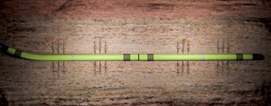
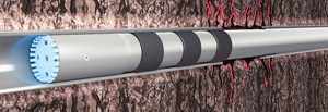
The application of solid expandable technology (SET) to recomplete/refracture a wellbore is based on expanding steel casing in the wellbore, mostly in relatively long, horizontal intervals, Fig. 1. By using solid expandable pipe vs. conventional OCTG, maximum ID is retained, facilitating high-rate fracturing, with accurate and absolute isolation of the old perforations.
RF INSTALLATION PROCESS
When installing an RF liner, wellbore clean-out is critical in the overall process for two reasons: first, getting the expandable liner to desired setting depth, and second, to provide necessary room between the expandable liner and ID of the base casing to allow expansion to take place. Even though cleaning horizontal wellbores (particularly with old perforations and fractured rock), and keeping them clean, is challenging, applying best practices and lessons learned from earlier installations maximizes success.
Planning considerations. Pre-job planning meetings with the operator include a detailed walk-through of the installation procedure and risk mitigation matrix. Collaboration between the operator and the actual installation personnel is essential to the job’s success and fully meeting the operator’s wellbore objectives. A primary consideration in minimizing installation risk is an understanding of wellbore tortuosity. An “as drilled” directional survey of the wellbore is utilized to run a drag simulation. The simulation will model the degree of installation difficulty, considering tortuosity and friction factors, and help in determining an optimal running-string configuration.
Wellbore preparation and best practices.2 Preparation of an existing completion for a refracturing liner amounts to having a clean wellbore, and maintaining it throughout the installation and expansion of the RF liner. The main concern, which has been identified through installations to date, is formation solids feeding in from the old perforations. Wellbore fluid properties, adequate circulating velocities, and full-gauge bottomhole assemblies (BHAs), equal to the drift diameter of the casing, will clean the existing wellbore; however, any continuing entry of solids from old perforations must be managed. Key steps include:
- Two clean-out trips in the wellbore preparation for most installations. The BHAs will include full-gauge mills, magnets, brushes and a junk basket.
- Mixing and pumping fine-loss circulation material (LCM) in an attempt to seal off old perforations to a degree, and possibly, gain full returns, if fluid losses to the formation are being experienced on the first of the two clean-out trips. This will help transport any sand/debris out of the wellbore. Pumping sweeps also will assist with solids transport.
- A second clean out trip will have a similar BHA as the first; however, prior to tripping out to run the RF liner, the entire wellbore is displaced with a polymer gel fluid and lubricant. The fluid will have rheology to suspend any formation solids that may enter the wellbore from old, open perforations. A lubricant will be added to provide a friction coefficient below 0.25, as indicated from the drag simulation.
- Minimize downtime during installation, including operations shutdown during the night (i.e.,12-hr operations). Minimizing downtime will take advantage of stable wellbore conditions and avoid debris entering the wellbore, where the liner has not yet been expanded.
Experience from refracturing liner installations, to date, has validated these best practices, with the successful deployment and expansion of the RF Liners.
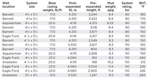
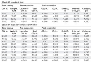
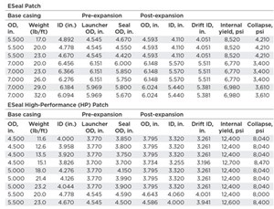
RF Liner installations. To date, 15 RF Liners have been installed, and, have effectively provided isolation of old perforations and a maximum ID for optimal fracturing and refracturing operations. RF Liners have been run in Barnett and Eagle Ford wells in Texas, as wells as Marcellus wells in Pennsylvania, Table 1. Eight of the RF Liners run, to date, were: High Performance (HP) RF liners. The designation of “HP” represents an RF liner made of 110-ksi material (standard RF liners are made of 80-ksi material). This distinction is used throughout the product line. The HP liner is very robust and provides an internal yield rating exceeding 10,000 psi for 5½-in. base casing, and 12,000 psi for 4½-in. and 5-in. base casings, with burst ratings considerably higher than the internal yield. The 110-ksi HP RF liners were developed when it was recognized that the demands of high pumping rates and resulting pressures were pushing the 80-ksi RF liners near their limit, Table 2.
Of the 15 liners installed to date, six have exceeded a 3,000-ft pre-expanded length, with the longest being 4,313 ft. Wellbore tortuosity, and the resulting drag analysis, dictates the maximum length of a liner. However, multiple liners have been run consecutively, when the drag analysis prohibits a single liner accommodating the entire length of the lateral. A recent installation utilized 3,000-ft and 2,900-ft RF liners to cover 5,900 ft of horizontal wellbore, which was subsequently fractured throughout the entire length of the horizontal. Throughout the 15 installations, old perforations were isolated effectively, providing the certainty that new reservoir rock could be fractured at rates close to and, in some cases, exceeding the original fracture stimulation.
A variation of the full-length RF liner has been discussed and is called the “hybrid.” This method would be a combination of first mechanically isolating the heel portion of the lateral with the RF liner, then using present, non-mechanical diversion to refracture the toe and mid-section of the horizontal wellbore. The heel section of the wellbore, isolated by the RF liner, would then be refractured using the plug-and-perf method. The concept is that the hybrid RF liner would cover the “thief” area, where unreliable diversion methods struggle to isolate the old perforations. This concept has yet to be tested.
MECHANICAL SOLUTIONS
Solid expandable and high-performance (HP) patch. The ESeal patch (Fig. 2) is designed for efficiency of installation, while maintaining the high mechanical ratings typical of all SET systems. The overall SET design was reviewed in detail, and a compact, single-joint patch was designed. All the components for installation/expansion are contained in that single joint. The efficiency for the operator, which adds significant value, is that the patch arrives at the rig as a single unit, ready to run into the wellbore. Nothing has to be made up, nor are individual components handled on the rig floor prior to being run. This also applies when a double-joint patch is run, as it does not have a screwed connection, either.
Consistent with the RF liner designations above, the ESeal Patch is made of 80-ksi material—the standard patch. The ESeal HP Patch is 110-ksi material. Both are available in a single-joint configuration with elastomers on each end. Additionally, a custom, double-joint version is available in the HP Patch. The single joint is generally 32–40 ft in length, a double-joint approximately twice the length, and the maximum repair length will vary, depending on the desired elastomer configuration.
Patch development. The HP Patch was developed at the request of an operator in North Dakota. It was first run in 2009 when the operator had three consecutive connection failures in its 4½-in. completion string, while pumping the first fracturing stage.3 Each failure occurred on three consecutive wells, where 10 fracturing stages were planned. The failure left a 3–to–4 ft gap, located near the heel of the well, putting the entire well at risk. A conventional “scab liner” repair would restrict the ID to where all remaining fracturing sleeves could not be shifted open (ball drop system) for the nine remaining fracture stages. The HP patch was developed and qualified for this specific application to provide the required ID and an internal yield rating in excess of 12,000 psi (Table 4) to handle fracturing pressures.
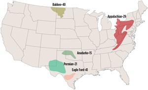
The HP Patch was run and expanded successfully across the parted pipe in all three wells. Each of the wells was then fractured successfully by completing all nine of the remaining stages, per plan. The operator stated that each repair would pay out in less than 20 days; however, the real value was in saving three wells that were at risk of total loss. Since those first three installations, the ESeal Patch has been installed in 179 wells of numerous North American oil and gas basins, Fig. 3. There have been two special HP Patch applications—installation in a “live” well with a rig-assist snubbing unit, and utilizing coiled tubing.
POSITIVE MECHANICAL ISOLATION
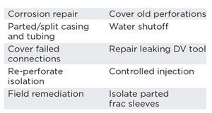
An ESeal RF liner can provide positive mechanical isolation of old perforations and enable the fracturing of new reservoir rock. Mechanical failures during a completion can now be repaired quickly with an ESeal Patch (or HP Patch). Ranging from a parted connection to covering perforation shot at the incorrect location, these patches have robust mechanical ratings that often exceed the casing that they are being expanded into and provide maximum ID to permit continuation of planned completion activities. ![]()
REFERENCES
- Cameron, J., “Refracturing horizontal shale wells with solid-steel expandable liners,” World Oil, p. 39, August 2013.
- Enventure Global Technology, Operations Department, “Best practices for cleaning out laterals for ESeal ReFrac installations,” Version 1.1, March 4, 2015.
- Enventure Global Technology, Case History, “ESEAL HP Patch,” Version 01, January 2014.
- Applying ultra-deep LWD resistivity technology successfully in a SAGD operation (May 2019)
- Adoption of wireless intelligent completions advances (May 2019)
- Majors double down as takeaway crunch eases (April 2019)
- What’s new in well logging and formation evaluation (April 2019)
- Qualification of a 20,000-psi subsea BOP: A collaborative approach (February 2019)
- ConocoPhillips’ Greg Leveille sees rapid trajectory of technical advancement continuing (February 2019)

