Re-fracturing simulations: Pressure-dependent SRV and shear dilation of natural fractures
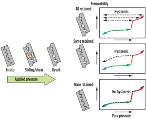
The concept of shear dilation of natural fractures is not new. Chipperfield et al1 wrote about the process of slipping planes self-locking into place, due to irregularities along the rock surface when fluid is injected into them. This mechanism of slipping and self-locking leads to enhanced permeability, even after the pressure drops with time during production (degree of permeability retention in the natural fractures), which is what is described as leading to an SRV region near the wellbore.
Figure 1 shows an illustration of how different self-locking behaviors lead to different hysteresis curves during production. The three scenarios on the right show permeability vs. pressure in the natural fractures. The green curves represent the elastic region where the permeability increases slowly with pressure during injection. At some critical pressure (called shear dilation onset pressure in this study), the permeability experiences a large jump (referred to as the shear dilation jump) and continues along the red curve. On the return path, the natural fracture permeability follows either the same path, as during the injection process, or exhibits a hysteresis.
Johri and Zoback2 introduced a concept called the percolation zone. In their paper, they state that natural fractures contribute to flow, only if they are hydraulically permeable and connected to the well via hydraulically conductive flow paths. The total surface area of this interconnected network of hydraulic fractures and permeable natural fractures comprises the percolation zone. Johri and Zoback show that the increase in the percolation zone is a function of the characteristics of the initial fracture population, to a much greater extent than the number of hydraulic fractures created. Areas of low, initial, natural fracture density do not experience a large increase in the percolation zone post-stimulation, even if the formation is severely hydraulically fractured.
Moos et al3 conducted a comprehensive study in an Upper Devonian shale gas reservoir at a site in southern West Virginia, using a model in which natural fractures provide the primary conduits for production. The SRV’s shape was determined by the natural fractures that were critically stressed during the hydraulic fracturing operation.
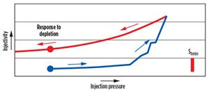
Moos4 also stressed that there is a need to understand the differences between various formations in terms of the shear dilation of natural fractures. Moos gave a detailed geomechanical explanation of how these planes of weakness shear, and gave an idea about ways to quantitatively constrain these effects. Figure 2 illustrates the relationship of injectivity to the injection pressure. This is similar to the natural fracture permeability hysteresis effect described in Fig. 1. The relative increase in injectivity can be used as a proxy for estimating natural fracture permeability enhancement in the field.
METHODOLOGY
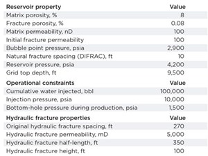
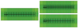
The study used a well producing from the oil window of the Eagle Ford shale to detail the idea behind a dynamic pressure-dependent SRV. A dual-porosity, dual-permeability (DPDK) reservoir model was chosen, with the permeability of the natural fractures as a function of pore pressure. The natural fractures were assumed to be closed at the start of the water injection process during fracturing. Their initial permeability was assumed to be equal to that of the matrix in the virgin rock. To simulate the hydraulic fracturing process, 100,000 bbl of water were injected through pre-designed hydraulic fractures. A wellbore, with a length of about 5,000 ft, was placed in the center of the box model with 19 fracture stages (one hydraulic fraction per stage).
A dilation table was used that captured the increase in permeability of the natural fractures as a function of pressure during the injection process, and the subsequent decrease in natural fracture permeability with a decrease in pore pressure during production. This essentially captures the shear dilation-induced, natural fracture permeability enhancement as pore pressure increases, and a certain degree of permeability retention upon pressure depletion.
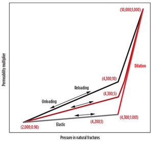
Figure 4 shows these curves labeled as elastic, dilation, unloading and reloading. The X-axis shows the pore pressure in any grid cell, and the Y-axis indicates the natural fracture permeability multiplier. All cells started on the elastic loading curve at 4,200 psi (the initial reservoir pressure). During injection, as the pressure increased, the permeability in the natural fracture cells increased marginally along a reversible elastic path until 4,300 psi, at which point the natural fractures underwent shear dilation and permeability rose rapidly along the dilation curve. This is consistent with natural fractures shearing along planes of weakness and, thereby, allowing fluid to flow with reduced pressure drop. It is noteworthy that the matrix cells did not exhibit dilation and, therefore, their permeability remained fixed.
The shear dilation onset pressure, the extent of the permeability enhancement, and the degree of permeability retention, depend on geomechanical rock properties, such as existing in-situ stress in the reservoir, fracture orientation, fracture size and coefficient of sliding friction along the fracture face. After 100,000 bbl of water were injected, a soaking period of 20 days was simulated, after which production was initiated at a constant BHP of 1,500 psi. After the injection process, pressure in the natural fracture cells decreased, due either to diffusion (during soaking) or depletion (during production). As pressure decreased, the permeability decreased, following the grey-and-maroon-colored unloading curves in Fig. 4.
For cells that had pressure values laying in-between the unloading and elastic curves on the dilation curve, multipliers were calculated, using interpolation. Cells that lay on the elastic curve at the end of injection simply followed the elastic curve back. The end points of the elastic curve were a 0.98x permeability multiplier at 2,000 psi and 1.001 times at 4,300 psi, where the shear dilation began. The permeability multiplier was 1x at the original reservoir pressure of 4,200 psi. The dilation curve went up to 1,000x permeability multiplier at 10,000 psi, the injection pressure.
The permeability retention for the grey unloading curve was 10x at 4,300 psi, and the permeability multiplier decreased linearly to 0.98x at 2,000 psi, thereafter. The unloading curves had a higher-than-initial permeability during pressure depletion, representing a hysteresis in permeability as the natural fractures close during depletion, but retain some of the enhanced permeability.
Matrix permeability was assumed to be invariant with pressure. Based on these assumptions and reservoir and fluid properties, a simulation model was constructed and history-matched to an existing Eagle Ford oil well, after which a refracture was simulated. Refracturing gave rise to a new SRV volume, based on a combination of existing pressure depletion and water injection.
History-matching was performed by changing the dilation table, reservoir properties and well completion parameters. Table 1 shows the reservoir and completion parameters obtained after history-matching. In the dilation table, the maximum shear dilation jump (corresponding to a natural fracture permeability multiplier of 1,000 at 10,000 psi) was determined by the volume of water that needed to be injected in a reasonable amount of time during the fracturing operation. The degree of permeability retention during production, and the slope of the unloading curve when the pore pressure drops during production, was adjusted, based on the well’s initial production and decline rate.
After 21 months of production following the original fracturing operation (as observed in the historical well data), a refracture was simulated. During the refracturing operation, the pressure in the cells increased again during injection, and permeability increased along reloading curves, as indicated in Fig. 4, or along an interpolated reloading curve between specified reloading curves.
Once the permeability-pressure combination reached the dilation curve, the permeability rose along that curve. If the permeability multiplier of any cell was along the elastic curve at its pore pressure, it continued to track the elastic curve, up to the point of intersection with the dilation curve. Thereafter, as the pressure increased further, permeability increase followed the dilation curve. In this model, the reloading and unloading paths were assumed to be the same.
Various scenarios were tested for evaluating re-stimulation performance. As a base case, the existing production was forecast without any refracturing. In the second scenario, fluid was pumped into the existing perforations without any new fractures being formed. In the third case, only the first quarter or so of the wellbore was stimulated, creating four new fractures. This is equivalent to pumping a diverter job that creates new fractures, only near the heel of the wellbore, since the pressure is higher at the heel than at the toe, due to frictional losses along the well. This could also be equivalent to placing a packer after a quarter of the wellbore and shooting new perforations between existing perforations and then pumping with diverters.
Lastly, in the fourth case, a mechanical isolation of the existing perforations was simulated. Sixteen new clusters were created in-between existing fractures, and fluid was pumped into them to create new fractures. In all cases, refracturing was done with 100,000 bbl of water injection.
Though the details of how operators perform their refracturing operations vary, it is likely that the results of most diverter-based refracturing jobs are closer to the second case, where an uncertain number of new fractures are generated.
RESULTS
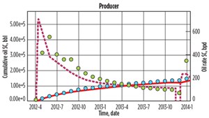
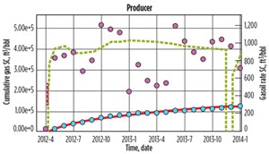
A reasonable history match was obtained for the Eagle Ford well producing from the oil window. Figure 5 shows the history match at 1,500 psi, BHP, for oil rate and cumulative oil. Figure 6 shows the history match for the gas-oil ratio and cumulative gas volume. Even though the historical data show an increase in production after 21 months, it could not be confirmed that this jump was, indeed, due to a re-fracturing operation. Therefore, the history match was done primarily on the “pre-jump” production data. However, a scenario was generated that would give the production as seen in the well after the jump, assuming that the well was refractured.
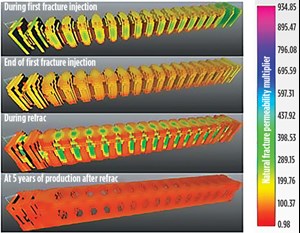
During the injection process, the permeability of the natural fractures increased as high as 500 times the initial permeability. Figure 7 shows the evolution of the natural fracture cells with at least 5x permeability, compared to the initial value during the injection process. As fluid is injected, pressure increases in the natural fracture cells, and the permeability increases in an growing number of cells. This gives rise to an evolving dynamic SRV around the hydraulic fractures, as pressure increases, as was observed in this model.
The reverse happens during production, as pressure depletes. The fourth image in Fig. 7 also shows the natural fracture cells losing permeability over time and eventually falling off the scale (these are the cells that appear like holes in the image) near the wellbore, as the permeability is reduced to less than 5x the original value. Not only was there a reduction in the enhanced permeability volume, but an inversion of permeability also was observed. The figure shows missing cells near the wellbore representing a permeability multiplier less than 5x the original value. These cells are surrounded by other cells that are more permeable, with a permeability multiplier of more than 5x.
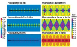
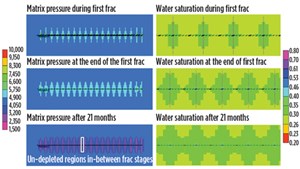
Apart from an inversion in permeability, an inversion in water saturation also may take place, where more water is produced from near-wellbore in the natural fractures, compared to farther away. Figures 8 and 9 show the pressure and water saturation in matrix and natural fractures, respectively, during first fracturing and subsequent production. The images in the left column show pressure maps. The images in the right column show water saturation maps. Each row represents different times in the life of the wellbore.
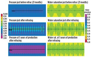
During injection, pressure and water saturation increase near the hydraulic fractures in both matrix and natural fractures. Figure 8 shows that even after nearly two years of production, the pressure and saturation in matrix cells between the hydraulic fractures remain near virgin values. Even the natural fractures cells (Fig. 9) do not show depletion in-between original hydraulic fractures, primarily because the area of enhanced permeability is limited to the neighborhood of the hydraulically fractured region. As for water retention in the formation, it can be seen that only matrix cells retain water, whereas the water saturation in the natural fracture cells is less than the initial amount at the end of 21 months of production.
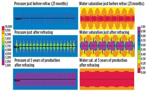
Figures 10 and 11 show pressure and saturation in matrix and natural fracture cells, respectively, just before refracturing, at the end of refracturing and after five years of production. As in Figs. 8 and 9, the left column indicates pressure, and the right column represents water saturation, with rows representing different times. A new fracture was created in between every existing fracture.
When pressure was studied in the matrix cells (image on left column, last row in Fig. 10) at the end of five years of production, significant pressure depletion was seen across the entire wellbore. This indicates that the refracturing operation was able to increase the recovery factor from the wellbore by a significant amount compared to initial fractures. Also, the water saturation map in the matrix cells shows significant retention of water across the entire wellbore. A similar result was seen for natural fractures (Fig. 11) in terms of pressure. However, natural fractures did not retain any water that was pumped into them during the two injection periods.
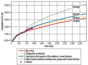
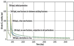
Figures 12 and 13 show 10-year oil recovery and flowrates for various refracturing scenarios. Re-stimulating the existing perforations only gave an incremental 24,000 STB over the base case, where there was no re-stimulation. Making even four new fractures and stimulating the natural fractures around them increased the 10-year recovery by 47,000 STB. The highest increment was seen with new fractures in-between every existing fractures—180,000 STB. Although it is difficult to say with certainty which one of these scenarios is most likely to occur, they provide reasonable bounds for the increase in recovery, due to refracturing.
Summary of history matching results:
- Cumulative oil volume without refracturing: 325,000 STB (5.9% recovery factor)
- Cumulative oil volume with refracturing:
- New fractures between existing fractures: 505,000 STB (9.1% recovery factor)
- Re-injection into old perforations: 349,000 STB (7% recovery factor)
- Four new fractures forming only near the heel of the wellbore: 383,000 STB (6.3% recovery factor)
CONCLUSIONS
The well-used in this study is shown to have symmetrical hydraulic fractures with similar fracture lengths. In actuality, it is known that fractures are rarely symmetric and seldom bi-wing. They often display effects of stress shadowing and unequal lengths. These complexities have not been modeled in this study. The idea of this study has been to explore the idea of a continuously variable SRV that dilates and contracts with pressure, in terms of natural fracture permeability. These ideas remain consistent regardless of the complexities outlined.
The following conclusions were drawn from this study:
- The application of a shear dilation concept leads to a variable SRV that is dependent on pressure, and therefore time. The SRV has the highest volume right after completion of the fracturing operation and decreases during production.
- Natural fracture shear dilation is a significant contributor to production.
- An inversion of permeability in the natural fractures takes place, as permeability decreases faster near the wellbore than away from the wellbore.
- Pressure and oil saturation profiles in the reservoir remain at near-initial conditions in-between existing fractures, providing a rationale for tapping into previously untapped areas by refracturing.
- Different refracturing scenarios were studied, based on completion techniques. These techniques included mechanical isolation that formed new fractures between existing fractures, diverter with no new fractures, and diverter application with a few more fractures. Mechanical isolation had, by far, the best incremental recovery.

REFERENCES
- Chipperfield, S. T., J. R. Wong, D. S. Warner, C. L. Cipolla, M. J. Mayerhofer, E. P. Lolon and N.R. Warpinski, “Shear dilation diagnostics: A new approach for evaluating tight gas stimulation treatments,” SPE paper 106289, presented at the SPE Hydraulic Fracturing Technology Conference, College Station, Texas, Jan. 29-31, 2007.
- Johri, M., and M. D. Zoback, “The evolution of stimulated reservoir volume during hydraulic stimulation of shale gas formations,” SPE paper 168701/URTeC paper 1575434, presented at the Unconventional Resources Technology Conference, Denver, Colo., Aug. 12-14, 2013.
- Moos, D., G. Vassilellis, R. Cade, J. Franquet, A. Lacazette, E. Bourtembourg and G. Daniel, “Predicting shale reservoir response to stimulation in the Upper Devonian of West Virginia,” SPE paper 145849, presented at the SPE Annual Technical Conference and Exhibition, Denver, Colo., Oct. 30–Nov. 2, 2011.
- Moos, D., “Improving shale gas production using geomechanics,” Exploration & Production, Vol. 9, Issue 2, 2011.

