Coiled tubing-conveyed artificial lift and cleanout systems optimize costs and production
Traditional rod-driven lift systems were designed for conventional vertical wells. Today, many wells have challenging characteristics that may wear significantly on downhole equipment, resulting in sub-optimal well production and high maintenance costs.
Over time, producing wells may require frequent workovers, due to equipment fatigue and output changes. Presently, conventional workover rigs must perform these operations. Before any workover procedures are initiated, the well’s production must be contained. This procedure usually requires killing a well with fluid, which can lead to sustained production degradation and, potentially, permanent loss of well productivity.
UMBILICAL COILED TUBING
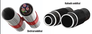
In 2008, CJS Production Technologies (CJS) based in Alberta, Canada, pioneered the encapsulating of multiple CT strings in a thermoplastic resin called FlatPak, to optimize installation of hydraulic and electric pumps without killing a well’s production. In 2013, CJS expanded its umbilical coiled tubing (UCT) technology to include an all-metal design called ArmorPak, intended for deeper wells with higher pressures and temperatures. Figure 1 shows the all-steel tubing configurations available in sizes up to 1¾-in., single tube diameter. A 2-in. design is under development.
UCT solutions have multiple tubes to facilitate complete isolation of the hydraulic drive fluid or the electric power cable from production fluids. Combined, these two products serve as the principal conduits to convey and actuate downhole pumps for artificial lift. A line of running equipment was developed concurrently, including injector assemblies, stripper heads and BOPs to allow most available CT units to run UCT products. These UCT-deployed systems support hydraulic reciprocating piston pumps, hydraulic progressive cavity pumps, jet pumps and ESP.
APPLICATION BACKGROUND
Hydraulic pumping systems have been used to lift formation water from natural gas wells, and pump hydrocarbons to the surface in oil wells. UCT systems can be used permanently to pump fluid or for temporary service operations, to reduce water levels and clean out sediment.
Using UCT and downhole pumping systems eliminates the need for a service rig. They can be installed without killing the well to facilitate live operations, minimizing the chance of formation damage or permanent loss of production. Additional efficiencies include minimizing installation time, reducing location footprint and avoiding revenue loss associated with downtime. UCT-conveyed electrical and hydraulic pumps are deployed in a rod-less design, enabling optimal placement while eliminating rod-associated equipment wear. In horizontal wells, pumps can be placed precisely in the well’s heel area, eliminating rod wear.
The company’s UCT and JetVak vacuum pump systems also can remove fluids or solids from the wellbore. In a well with low bottomhole pressure, lost circulation during foaming or nitrogen clean-out can be problematic, due to the hydrostatic pressure of returns up the annulus. Using the company’s vacuuming tool, the hydraulic loop is closed, and the well pumps continuously with limited backpressure, thereby cleaning the wellbore.
ALASKA ESP/HSP CASE STUDY
Two all-steel, UCT-conveyed permanent pump systems were installed recently in two Alaskan wells and placed onstream for an Alaskan producer (AKP).
Well A. The well went onstream in October 1998 and produced over 90 Bcfg through December 2014. During this time, the well produced negligible amounts of water and did not require intervention. However, starting in 2007, water production increased. By late 2014, rates approached 500 bwpd. During 2014, declining gas output created difficulties in lifting excess water. By February 2015, the well loaded up and quit producing. Prior to experiencing water-loading, this 4,000-ft well produced 7.5 MMcfgd.
Well B. The well went onstream in January 1996 and produced 20 Bcfg through early 2013. It produced negligible amounts of water for the first 12 years. From 2011 forward, water production increased. By early 2013, rates varied between 30-50 bwpd. This caused the well to load up and cease producing. Prior to this, the 4,000-ft well produced 4.0 MMcfgd.
Investigation of lift solutions. In November 2012, the operator contacted CJS to investigate the potential for using UCT technology to install pumping systems in the above-noted Alaskan wells. A drilling rig in the area had been used for workovers, however the cost of this approach would be significant, due to mobilization, set-up, and time on location. In 2014, CJS was contracted to manufacture and deliver UCT-conveyed ESPs and hydraulic submersible pump (HSP) systems, and provide on-location services to install pumping systems on the case study wells. An intermediate-depth tractor-equipped CT unit installed the UCT pumping systems. Including the aggregate costs of the manufactured pumping systems and associated installation costs, the operator solved the issues and recompleted these wells at considerable savings, compared with the traditional rig-based alternatives.
Following the process, and during the electric pump system design phase, numerous AKP reviews took place, and significant redesign occurred to satisfy the producer. By October 2014, the pump systems were ready to install. Specific to the all-steel ESP, CJS and its associates designed the following system for use in Alaska:
All-steel UCT system. A 1½-in. dual-banded CT was preloaded with specially designed, custom-manufactured cable to power the downhole ESP.
Pump connector. The pump connector, threaded to the top of the ESP, connects to the dual-coil string. It leaves room to use cable splice technology, to connect the ESP cable to the system’s cable. A profile in the production side of the connector allows a dart to be dropped and seal off the production coil.
Isolation and coiled shearing. A wireline-retrievable plug was set in the pump profile connector and pressure-tested to provide isolation during running and cutting of the coil. A tapered guide on top of the pump connector was incorporated to mitigate the risk of getting planted. A shear sub was designed to run above the ESP pump, to allow the CT to pull free from the pump connector. The power cable separates downhole at the splice connector.
Wellhead penetrator-electric feed-through. A custom downhole penetrator and wellhead feed-through system were designed to support the CT-deployed ESP system.
Tubing hanger. A two-piece tubing hanger was designed to be installed around the dual-coil string that grips the coil, as it is landed inside the wellhead. A nitrile rubber element ensures well control.
AKP field operation. Field operations were deferred until 2015, due to weather. The equipment was shipped to Alaska in July 2015 and rigged up on Well A. AKP killed the wells for these operations, while waiting on the service provider to complete its CT stripper development that would meet AKP’s well control guidelines. The wellhead workover stack and injector head were unusually tall, requiring a boom crane height of over 80 ft.
The all-steel ESP system was installed in Well A, which was placed onstream immediately. As of this writing, the well had returned to a rate of 3.8 MMcfgd while lifting 600 bwpd. The well continues to build rate, as the system operates at capacity.
Last August, CJS installed a HSP reciprocating pump system in Well B. At that point, the HSP had evacuated the well of all kill fluid and was pumping 28 bwpd, with gas rates of 200 Mcfgd. The pump was unloading at rates below the 40-bwpd design, due to an underestimated friction loss in the ¾-in. concentric hydraulic line, restricting the pump stroke rate. Although under the designed capacity, the pump can achieve a “pumped-off” state.
Subsequent developments. The service provider has designed a dynamic pressure containment BOP CT system that will facilitate live well deployment of UCT. This pressure containment system works with an ArmorPak CT umbilical. The dual-conduit clamping system does not degrade the elastomer inserts that contain well pressure when running into a “live” well under pressure. This should be available in the near future.
CASE STUDY FINDINGS
This operation proved that an electrically powered pump system could be installed reliably on a rig-less, CT-deployed basis, using UCT while providing several advantages.
UCT installation of an ESP is more time- and cost-efficient, compared to traditional installation methods, by eliminating the need to engage cable spool units when conveying electric pumps, thus reducing mobilization, lease footprint and associated costs.
Upon validation of the UCT dynamic stripping system, UCT ESP installation would provide live-well ESP deployment, reducing the costs of well kill operations and the possibility of decreased or permanent loss of well productivity.
UCT methods do not require a wet connection, unlike other rig-less ESP installations. This project found that the introduction of the ESP cable into the UCT can have negative implications when deploying the CT. Improvements were made to the manufacturing/clamping process to resolve these problems.
UCT-deployed HSP. This operation proved that a hydraulically powered pump could be installed reliably on a rig-less, CT-deployed basis, using UCT while providing a number of advantages.
One, installation of an HSP requires three tubes, two for pulsing the hydraulic piston and a third to deliver production fluid to surface. Installation is considerably more efficient when installing a dual-UCT, with a concentric tube in one side of the UCT to complete the hydraulic circuit.
Two, UCT installation of an HSP is accomplished in less time, and for a considerable cost savings, when compared to traditional methods. UCT-conveyed HSP systems to operate effectively to dewater conventional gas wells in comparison to conventional sucker rod pumps.
Three, UCT-conveyed HSP pump systems can effectively pump natural gas with hydraulically forced full strokes of the production piston, thereby operating in a “pumped-off” state, without gas locking of the pump, itself. Also, upon validation of a UCT dynamic stripping system, UCT HSP installation provides the advantage of live-well HSP deployment, reducing costs of well kill operations and the possibility of decreased well productivity.
Last, the concentric design created more-than-anticipated friction losses in the hydraulic lines. Future installations will take this into account, including considerations for running larger-diameter strings or use of friction-reducing additives.
CANADIAN PROGRESSIVE CAVITY PUMP CASE STUDY
Two FlatPak thermoplastic-jacketed UCTs conveyed permanent hydraulic progressive cavity pump systems in cold, heavy-oil wells in Lloydminster, Alberta.
Well C. The well is a recently completed, horizontally drilled borehole, with a 4,000-ft MD and a TVD of 2,200 ft. The operator contacted the service provider to install a UCT hydraulic-drive, progressive cavity pump (HDPCP) to solve issues in lifting heavy crude.
The engineering team researched the available hydraulic pumping equipment and selected a high-torque (400 ft/lbs), low-rpm hydraulic motor. A triple-thermoplastic UCT included two 1-in. coiled tubes to complete a closed-loop hydraulic circuit and a third, 1¾-in. production tube. The UCT had a ¼-in. capillary tube for continuous injection of friction reduction chemicals. Additionally, two electric conductor wires carry pressure information from downhole recorders to surface reporting equipment. After manufacturing the HDPCP system, it was delivered to the field, to be installed by a local CT unit.
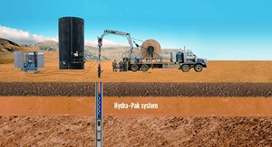
In Fig. 2, a schematic of the operation shows the advantage of applying UCT with a rig-less unit to install a HDPCP pump, to prevent rod wear, manage fluid draw-down and prevent well pump-off.
Hydraulic progressive cavity pump system. The HDPCP pump was landed at approximately 2,700 ft, MD, and placed on production at an 85° inclination. Initially, the well produced negligible formation water with minimal sand cuts and 57 bpd of high-viscosity oil (25,000 centipoise). It was anticipated that discharge pressures would be in excess of 3,600 psi, due to friction associated with pumping the viscous crude through 1½-in. tubing from 2,700 ft.
To minimize the damaging impact of high discharge pressure, a friction-reducing chemical was pumped through the injection tube in the UCT. Initial pump discharge pressures were measured at 1,600 psi, with a hydrostatic pressure of 840 psi, proving that the chemical was reducing tubing friction. Both pump intake and discharge pressures were recorded continuously during operations. By monitoring pump intake pressure, the operator actively controlled the fluctuating annular fluid levels and, thereby, speed or slow pump rates to optimize fluid drawdown to prevent production loss by pump shut-down.
Over several months, oil production declined naturally to 31 bpd. Sand accumulated in the pump and increased torque levels unacceptably. Because the progressive pumping unit is configured in a torque-neutral position, it can be reversed in its installed downhole position, unlike a traditional rod-drive PCP. In this case, only a field technician was required to change the hydraulic system flow, to reverse the rotor and flush the pump free of solids. Following the cleaning procedure, the pump returned to normal operation without issues. The HDPCP continued in production on this well for about six months, until the operator pulled the pump and converted the borehole to a water injector.
Well D. The well was a relatively new horizontal borehole, drilled to 3,900 ft, MD, with a TVD of 2,100 ft. The HDPCP pump was landed at approximately 2,600 ft, MD, at an 85° inclination. Initially the well produced 19 bpd of water-free high-viscosity oil, with minimal sand production. The completion of this well was identical to Well C, regarding UCT deployment, the downhole hydraulic drive system, a chemical injection tube, electrical conductors and pressure recording sensors.
While this well produced, the operator trialed the system without using continuous chemical injection, resulting in high pump discharge pressure and pre-mature pump seal failure. Subsequently, the pump was pulled, the seals were replaced, and the pump was re-landed. This well remained onstream for about nine months until the operator took it out of service.
Subsequent developments. Various operators have sought a HDPCP that would yield higher volumes of heavy oil, requiring greater torque than was available from the initial pump. After researchi, CJS could not locate a higher-torque hydraulic motor than those installed in wells C and D. CJS subsequently designed a hydraulically-lubricated torque conversion box fed by the UCT’s hydraulic circuit. This equipment was designed to reduce a radial-style, high-rpm hydraulic motor to less than 200 rpm, and conversely increase torque output from 40 ft/lbs maximum input torque up to 900 ft/lbs output torque. This more than doubled the previously available output. In January 2015, bench testing commenced, and with minor modifications, it was validated for field trial.
CASE STUDY FINDINGS
This operation proved that a hydraulically powered PCP could be installed reliably on a rig-less, CT-deployed basis, using UCT with several advantages.
First, installation of a conventional PCP requires workover and rod rigs, or a co-rod unit, to install the necessary pump, production tubing, and drive rods. UCT installation of a HDPCP is considerably more efficient, requiring less equipment. This reduces mobilization, lease footprint, time on location, and associated completion cost, all while enabling live well service.
Second, the HDPCP can be operated in a horizontal inclination to optimize production and reserve recovery, while eliminating concerns of rod and tubing wear, production downtime, and incremental service costs.
Third, unlike conventional PCP limitations, the HDPCP can be reversed to flush solids from the tubing and pump. Also, integrated electrical cables in the UCT can monitor pump intake pressure to optimize fluid drawdown and avoid pump-off conditions.
Last, chemical injection lines can be incorporated into the UCT, directed at the pump intake to treat torque increases due to friction, solids, scale and wax.
VACUUM CLEANOUT CASE STUDY
Eight CBM wells in Oklahoma, producing from the Hartshorne coal, were chosen to perform well clean-outs, utilizing a specialized jet pump conveyed on the thermoplastic-jacketed UCT system. All wells were of similar depth, with an average TVD of 2,200 ft, and MD of 4,300 ft. The vacuum assembly was run on a dual, 1½-in. UCT string, using one CT member for power fluid injection and the other for fluid returns. The jet pump was equipped with a nozzle-and-throat configuration that was optimized for the candidate wells. The pump intake was equipped with an appropriately sized screen, through which solids could be produced, but which would prevent over-sized particles from clogging the pump. Also included was a combination back-pressure valve and nozzle, which acted as a forward jet, if sand or coal bridges were encountered, preventing normal forward advancement of the jet pump assembly. When pressurized by pumping down both UCT strings, the valve would open, and the tool would jet forward into the bridge. Once the bridge was broken, jet pumping resumed, and fluid and solids were produced to surface.
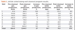
Using the vacuum system, eight CBM wells were cleaned over three days. Results in Table 1 indicate that some of the wells had marginal or no increases in gas output while displaying large gains in water production. This may have stemmed from water build-up in deeper zones of the wellbore that were blocked off previously by coal bridges. Using vacuuming and jetting, all coal bridges were removed and cleaned out successfully to the surface. By creating a low-pressure vacuum in the wellbore, there was no damage to the reservoir, and the well’s productivity increased after the service was completed. Previous cleaning methods included costly underbalanced foaming. Overall average increase in project gas production was 27%, while Wells 1 and 8 more than doubled their in gas production rates.
CASE STUDY FINDINGS
UCT deployment, used to convey and power a jet pump, enables operators to remove solids and coal bridges to produce fluids and sediment to surface.
The vacuum system is a rig-less, UCT-deployed, live-well, rod-less technology. CTU cost and time efficiencies were gained, compared to conventional work-over rig cleanouts. The vacuum system is well-suited for under-pressured reservoirs, for lifting solids while minimizing reservoir damage associated with traditional well cleaning methods. This technique has been validated in over 600 operations, showing that UCT assures high-flow velocities within the CT. ![]()
- What's new in production (February 2024)
- Using data to create new completion efficiencies (February 2024)
- Prices and governmental policies combine to stymie Canadian upstream growth (February 2024)
- U.S. operators reduce activity as crude prices plunge (February 2024)
- U.S. producing gas wells increase despite low prices (February 2024)
- U.S. drilling: More of the same expected (February 2024)


