Scanning an existing processing facility into a 3D virtual environment helps determine remedial pipe runs and create up-to-date drawings.
David S. Stevens and Christopher T. Comardo, Mustang Engineering, Houston
Laser scanning technology has existed for less than a decade, yet it has already become a powerful tool in the oil and gas industry, gaining wide acceptance for brownfield applications, both onshore and offshore. Its use is especially important in an economic climate where budgets are curtailed and renovating existing facilities is a crowded operation. Offshore platforms are a good example, as they can be as complex as a refinery but with much less real estate to work with.
Laser scanning is a means of obtaining a 360° data capture, providing a 3D view of a facility. With a scanning camera operating at ultra-fast speed, it collects up to 500,000 individual surface geometry measurements per second and creates a “point cloud” that can be viewed with specialized software. Basically, laser scanning brings a “smart” digital picture of a facility back to a designer who, using the industry’s predominant 3D CAD modeling software, can design or redesign facilities. It can add surety to cost, implementation and safety to redesign.
BACKGROUND
Two different types of scanners are commonly used. The older, time-of-flight-based technology, determines the distance between object points and the scanning device by emitting pulses and detecting the echoes from the object, measuring the travel time to and from the object. This technology is best suited for medium-to-long-range scanning and captures about 5,000 data points per second. It has a range of about 300 yards so that the scanner can cover a large area without being repositioned.
The newer, phase-based technology can collect data about 10 times faster but has a shorter range, so the scanner has to be repositioned more often. This technique is based on a phase comparison from a continuous laser light beam wave being emitted. The phase of the incoming modulated wave from an object is compared with that of the outgoing wave. The distance of the object is measured by the phase difference between the transmitted and received light modulation. Both technologies are effective for specific requirements and, on certain projects, it is advantageous to use both scanners in tandem and coordinate their results.
LASER SCANNING BENEFITS
Laser scanning technology has many advantages over traditional survey and manual field measurements.
Accuracy. Laser scanning can record measurements to within 1⁄8 in. and as far away as 300 yards. Using the millions of measurements in the point cloud, the camera captures everything within view. This results in an error rate of below 1% and virtually eliminates the additional requirement of field checking the facility. Coupled with companion online software, designers can create highly accurate as-builts quickly and easily.
Cost and time savings. Laser scanning projects gather the necessary information with a 2 or 3 person crew, with trips as short as a few days. Conversely, traditional methods often require 8 to 10 persons of various disciplines—piping, structural, instrument and electrical—who could spend months on multiple trips surveying the facility to gather the same information, yet not as accurately. When used in remote or international locations, laser scanning can dramatically reduce travel, housing and per diem costs.
When a designer, trained in laser scanning, is part of the team, they have the added ability to understand the data being collected and work with it easily back at their work station. Design cycle time can be greatly reduced as a result. Since virtually all of the scans can be collected from various survey points and registered together before leaving the site, there is normally no need for a repeat visit by a checker as would be needed to verify manual measurements. Rework, because of faulty or incomplete information gathered manually, is essentially eliminated.
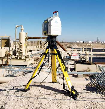
Safety. Laser scanning can be accomplished on the ground or on the deck of a fixed or floating facility, Fig. 1. Climbing ladders is minimized. Scaffolding or harnesses are normally not required as the scans can encompass elevated structures with their viewing capability. Job safety is further improved with fewer people on the site, particularly important in potentially hazardous areas, under crowded conditions or in facilities with small footprints.
 |
|
Fig. 1. A laser scanner can capture images above and below, close up or from 300 yards away.
|
|
Future reference. In addition to its use on the immediate project, laser scanning creates an updated as-built 3D point cloud of the facility which can be stored and used for future projects. This is advantageous on brownfield upgrades and enhancements. Using conventional surveying methods, the same project could take months or even years.
Shared information. Multiple disciplines working on the same project are able to utilize the same scanned data. Not only is this cost effective, but it helps assure consistency of design information. Clients and vendors, too, can use the information on a shared network to visualize the project as it progresses and play an active role as participants in the project.
Design team satisfaction. With additional and more accurate information, the project designer is able to make better decisions, avoid rework, accurately identify potential piping clashes and be more productive. With virtually no surprises from field data, designers experience fewer frustrations when designing a project and can be more involved in its success.
CASE STUDIES
With each successful project, laser scanning becomes more accepted. Satisfied clients have come to rely on the technology and are often mandating its use for future brownfield projects. The stories are numerous.
Giant platform survey. A blast remediation study was commissioned by a major operator on its 13 year-old, 8-pile fixed platform, one of the largest in the Gulf of Mexico. The structure rests in about 1,300 ft of water near the edge of the Continental Shelf. The study was to be used to create as-builts for the platform, which has undergone numerous additions and upgrades since first installed. Existing as-built drawings were provided in 2D CAD programs and were not complete or up-to-date. The study was to determine “what if” scenarios for potentially hazardous areas on the topsides and to make certain that the facilities afforded maximum safety to operating personnel and equipment. The scans identified density of piping runs, distances between living quarters and operating areas, deck configuration, pipe line sizes, vessel and valve locations and other pertinent information for promoting safe operation.
During six days onboard the platform, a crew of three shot more than 250 scans using a phase-based scanner and averaging 40 scan positions per day. During that period, they were able to capture approximately 95% of the facility, the remainder not being critical space. About 20 GB of data were collected on each of the three full decks and one mezzanine deck. The scanning, data registration and point-cloud coordination were all completed while the crew was still at the site, verifying the completeness and accuracy of the scans. The scan results were immediately used by electrical engineers who had manually measured for additional cable trays. They were able to verify their measurements. It was estimated that the entire project would have required a crew of 7 to 10 technicians as much as 6 to 10 months to complete the job manually. The scans were also used for an AFE for a proposed module addition.
Erroneous drawings updated. One of the earliest spars installed offshore Louisiana was being modified to replace six living-quarters modules with a new, single-quarters unit and a helipad on top. During the project’s detailed design, it was noted that the existing general arrangement drawings had an 18-in. discrepancy when compared to actual dimensions. The location of the error could not be pinpointed, but would impact the placement of the building. The quarters building was under construction when the discrepancy was discovered, requiring a fast track solution to assure that the building and attendant cable routings would fit in the available deck space.
A two-person laser survey crew flew offshore to the facility, completed 29 scan positions on three deck levels and was off the platform heading home in less than seven hours. The data captured was registered and put into a partial PDMS 3D model where it could be integrated into new general arrangement drawings. The scans indicated that the discrepancy was in one corner of the platform adjoining the quarters. The scans were put into the model within one business day after the crew completed the project, making them available to the designers for verification of the general arrangement drawings. The same survey, using two draftsmen, would have taken at least a week offshore, and still might not have provided the same level of data accuracy.
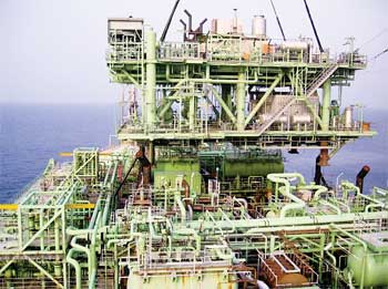
West Africa error detection. In 2007, Mustang was hired to conduct a laser scan to establish an as-built configuration for the brownfield upgrade of an FPSO (Fig. 2), with the demolition of old equipment and the addition of a new 750-ton gas compression and injection module to increase gas lift by 25 MMscfd and gas injection by 10 MMscfd. The 1,100-ft-long x 170-ft-wide vessel had been working for five years offshore West Africa in water depths of 2,200 ft. Among other reasons for an extensive scanning project, the laser scan was used to survey four pre-installed stabbing points on the vessel’s topsides to make certain that the points matched the drawings for placement of the new module.
 |
|
Fig. 2. On large offshore platforms and FPSOs the original design and piping drawings can often be missing or incorrect.
|
|
Results from the scans revealed that one stabbing point was about 3-in. off its mark. If the discrepancy had not been detected and, because of the extremely tight fit for placing the module, the error would have necessitated welding repairs and caused a delay in the derrick barge schedule for setting the module. Resulting cost escalations could have easily exceeded $1 million. Because the scanning team was able to understand the ramifications of the error and interpret the scans on-site, the structural designers were able to move the footprint over to accommodate the necessary realignment. The scans by the three-person team in this remote location were completed in seven days (less than the 10 days budgeted). Alternatively, the same job would have required several months by a survey crew and, most likely, the stabbing guide placement error would have gone undetected.
Reconstructing information amidst scope changes. The group was contacted by a company operating several natural gas fields on the US Gulf of Mexico shelf. In one of the fields offshore Louisiana, the company inherited a 20-plus year-old, eight pile fixed platform operating in about 200 ft of water. The client wanted to increase production from the facility and bring it up to current standards, but had no background information on the status of the platform. There were no P&IDs available from the major operator that had previously managed the facility.
After an assessment of the facility and an understanding of the client’s objectives, a two-person laser scanning team went onsite, performing more than 50 scans of the facility’s production and cellar decks in a single two-day trip. The scanning saved the client both time and costs as the project ultimately had seven scope changes. Manual surveying would have required multiple trips to resolve the changes and about 13 man-weeks to accomplish.
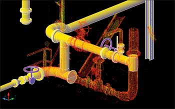
The scan results, accurate to 3 mm (vs. 1–3 in. with a manual survey), were then back-designed in 3D CAD software to create new P&IDs from which to develop a facilities layout and cost estimate. In a client meeting, the design team was able to project the laser scans overlaid with the 3D drawings to demonstrate precisely how the expansion would be undertaken, Fig. 3. The project took only four months to complete the detailed design phase allowing the revamp to go forward. The generated information from the scans will provide useful and easily updated information for future alterations.
 |
|
Fig. 3. 3D scanning makes for easier and more certain pipe re-routing around obstacles.
|
|
LOOKING AHEAD
While this technology is mostly used for brownfield work, laser scanning also has applications for new construction. Dimensional control of piping spools being welded in fabrication yards is one application. Another is the verification of correct placement of vessel flanges and the orientation of other equipment on skid modules in the yard. This accuracy is especially important with high-alloy, high-wall-thickness steel, where rework can be very expensive. Poor alignment on a single vessel nozzle can affect the placement of multiple pieces of equipment. The combination of laser scanning and a designer’s knowledge of piping helps assure that the fabricated piping meets design criteria, saving the fabricator potential rework and offering the client valuable quality assurance.
As laser scanning awareness increases, more clients gain knowledge of its capabilities and award repeat work. Time savings, increased safety and highly accurate results are the reasons. We believe that use of a trained designer as part of the laser scanning team, either doing the scanning or overseeing technicians, is a plus in getting usable results. We speculate that the technology will continue to grow such that, eventually, designers will use it like they use tape measures today and that laser scanning will ultimately be part of the design of every project. 
|
THE AUTHORS
|
| |
David S. Stevens, Laser Scanning Coordinator at Mustang, has 28 years of experience in piping design, project design coordination and lead designer for a multitude of offshore production facilities. He is skilled in the integration of design and laser scanning technology.
|
|
| |
Christopher T. Comardo, Piping Design Manager, has more than 30 years of experience in piping design, drafting room supervision, design coordination and field construction follow-up. He has more than 20 years of experience in managing various types of 3D-modeling software for offshore and onshore projects.
|
|
| |
|


