99-09_extraordinary-lowrie_fig1.htm (Sep-1999)
 |
|
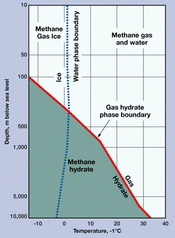
Fig. 1. Gas-hydrate phase diagram, showing the stability fields of the water-ice-methane-hydrate system.1 The presence of ethane, HxS, CO2 and propane with methane in the hydrate will shift the hydrate phase boundary to the right: such "contaminated" methane, such as occurs in the Caspian Sea, can convert to hydrate at 50-m water depth. Result of contaminated / mixed natural gases is an increase in the P-T methane-hydrate-stability field. Heat increase, depressurization or introduction of a methane-creation inhibitor (such as a salt solution) will move the phase boundary left and down. Free gas and fresh water will be produced as a result of movement of the P-T point, when its new position is right of, and/or above, the gas-hydrate phase boundary. |
Copyright © 1999 World Oil
Copyright © 1999 Gulf Publishing Company


