Innovations in autonomous control gain adoption for wellsite and pipeline chemical injection
Autonomous local control is local monitoring of multiple parameters, combined with intelligent control adjustments, and made automatically without manual interaction, analysis or human input. This is a natural progression, as technology transforms oil and gas production into a digital oil field.
For producers, two of the highest operational costs are manpower and chemicals. Traditionally, chemical pumps are not reliable or accurate. As a result, over-injection of chemical becomes a safer and less-expensive option than dealing with well problems created by insufficient application. In most cases, operators apply approximately 20% to 30% more chemical than necessary. In addition, a vast majority of the chemical pumps on the market are adjusted manually, making automation difficult at best.
INTELLIGENT CONTROLLER
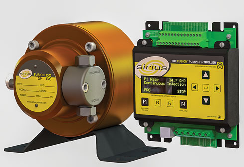
Sirius Controls Inc. has developed Fusion technology that addresses the over-injection issue and manpower costs by using an autonomous local control device, Fig. 1. There are several ways that autonomous local control reduces producers’ costs through manpower reduction and chemical optimization. But how will automating a chemical pump’s response to changing process conditions, environmental conditions, and automating the operator’s tasks, benefit the producer?
Autonomous control adjustments for changing conditions. Chemical pumps, operating on solar power, have problems related to accuracy and consistency, due to voltage variations. Most of the time, the discrepancy between the recorded rate of injection, and the amount of fluid injected over a longer period of time, is misunderstood or unexplained. However, the principles behind these errors are quite simple.
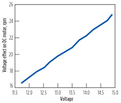
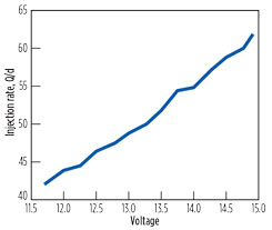
All brushed DC motors have a linear relationship between voltage and RPM, meaning that as voltage decreases or increases, so does the motor’s RPM. The vast majority of solar chemical pumps in the oil and gas industry use a DC motor coupled to a positive displacement chemical injection pump. This means that changes in battery voltage have a direct effect on injection rate, Fig. 2.
There are several reasons that can cause the voltage supply to the DC motor to fluctuate:
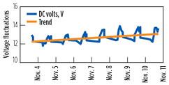
- Solar panels are used to charge the batteries during the day. At night, or during days of cloud cover, the batteries discharge. Lead acid batteries in their fully charged state are about 13.8 volts and fall to 12.0 volts in a nearly depleted state, a 13% difference. A properly designed solar system will fluctuate 1.0 to 1.3 volts from day to night; approximately a 7.5%-to-10% change in voltage. The variations in the voltage of a solar pump are due to: 1) day/night variation; and 2) trend change over a week, Fig. 3.
- Ambient temperature changes alter the charge levels of standard solar-charge regulators. From 68°F to minus 22°F, the voltage charge levels are adjusted by approximately 1.5 volts, or about 10%.
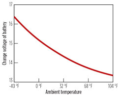
- Battery voltage also fluctuates with ambient temperature. Typical lead acid batteries will change by approximately 3 volts, when temperatures fluctuate from minus 40°F to 104°F. Variations from day to night of 18°F can result in swings of 3% in the battery’s voltage, Fig. 4.
The fluctuations in voltage described above will result in similar changes in injection rates. Depending on the system’s design, geographic location, climate, and the battery’s state when the system was calibrated, the rates can easily vary 10% to 25%, or more, due entirely to changes in voltage.
Figure 5 shows the response of a pump’s injection rate, as the voltage is changed along the normal voltage cycle of a battery.
The variability in injection rate explains why many operators experience different rates when they calibrate in the morning or in the afternoon. Calibrating a system on a voltage peak will result in under-injecting. Conversely, calibrating a system when the voltage is low results in over-injecting, when the sun is shining, or the batteries are fully charged.
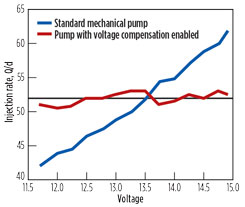
Autonomous local control can mitigate the effects of voltage fluctuations and stabilize the chemical injection rate, Fig. 6. The injection rate was set to 52 Q/day (horizontal black line). The blue line indicates the response of a commonly used pump operating over the range. As shown, the injection rate varies directly with voltage. The red line shows the response of the same, pump using an Intelligent controller with the patented “voltage compensation” feature enabled. The battery voltage is recorded during the pump calibration process and used to automatically compensate and adjust the injection rate, as voltage naturally fluctuates. The error without voltage compensation can exceed 30% over the range that a battery operates, from full charge to depletion.
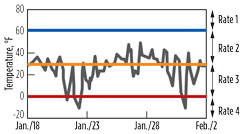
Another example of the benefits of autonomous local control is the use of a table within an intelligent controller to adjust methanol rates, based on ambient temperature. It is common to turn pumps on and off, based on a single temperature; however, this more complex method allows the producer to optimize injection rates over a series of temperature zones. This significantly reduces the amount of methanol consumed. Traditionally, using an on/off signal, the methanol would be injected constantly at the same rate after temperature dropped below 55°F to 60°F (blue line). Using autonomous local control, the methanol is controlled at different rates, based on the temperature at the time, significantly reducing the chemical injected. Temperature swings over a two-week period at a location in Montana illustrate the situation in Fig. 7.
Adjustments for changing process conditions. All pumps exhibit sensitivity in their output, due to injection pressure. This is commonly known as the pump curve. The curve represents the rate response of the pump, due to changes in process pressure. Many factors contribute to this, including DC motor loading causing a drop in RPM; compression of elastomers and piston seals; fluid compressibility; and others. Traditionally, chemical injection pumps are calibrated at a given pressure. When the process pressure changes, the output of the pump will vary as you slide up or down the pump curve. These errors can be significant, and can easily exceed 50% or more of the set injection rate, Fig. 8.
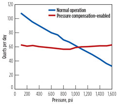
Using patented motor technology and unique pressure sensing software, changes in process pressure can be detected. The detected pressure changes can be used to correct the pump’s output and essentially flatten the pump curve. The red line (Fig. 8) shows how the error in injection rates, due to changes in pressure, are eliminated.
VALUE ADDED
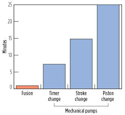
Virtually all operators/pumpers have been frustrated, calibrating and making changes to traditional, manually adjusted, mechanical chemical pumps. To adjust rates, they use a series of charts, tables and calculations to select the optimum pump, piston, stroke length, and on/off duty cycle. This can take an experienced operator 5 to 30 min., depending on the number of calibrations required. Over the course of a year, the man-hours logged, making these adjustments, result in thousands of dollars of wasted capital resources.
The utilization of an intelligent controller makes the calibration process relatively simple. It is only necessary on the initial set-up of the pump. During the calibration process, the operator is prompted for the drawdown. At this point, the intelligent controller has all the required information to control the pump directly in quarts/day, or other units of flow. The flowrate is now entered and displayed in quarts/day, rather than an arbitrary number or a unit of time or cycle rate.
Further rate adjustments can be performed with two buttons, which instantly change the injection rate of the pump by accurately adjusting the speed of patented brushless motor technology, resulting in precision RPM variation that provides continuous injection into your process for the most effective chemical treatment. At extremely low injection rates, the controller uses patented software to automatically change from continuous to intermittent flow, resulting in a seamless change for the operator. No tables, charts, calculations or manual/mechanical adjustments are required.
A comparison of time required to make a rate change, using the intelligent Fusion controller and a traditional, manual, mechanically adjusted pump is illustrated in Fig. 9.
FIELD APPLICATION
A midstream operator in the Permian basin was having high pipeline corrosion problems. Traditional mechanically controlled chemical injection pumps were used to add corrosion inhibitor. Corrosion coupons were used to determine metal losses, which exceeded 1.8 mills/yr. These traditional pumps were turned on and off with a timer to provide chemical to treat the process fluid. Atomizers were used to help disperse the chemical to improve the effectiveness of the chemical. Due to the intermittent nature of the pump and timer, a pulsation dampener was required to reduce slugging through the atomizer nozzle. This intermittent injection caused pockets of untreated fluid through the pipeline. In an unsuccessful attempt to decrease metal losses in the pipeline chemical injection rates had to be increased.
To improve pipeline corrosion loss, Sirius solar powered pumps with smart controllers replaced the traditional mechanical pumps. The nozzles on the atomizers were resized to reflect the continuous injection rather than intermittent pumping. The pulsation dampeners were removed from the process because the continuous flow eliminated sluggish pump behavior. Voltage compensation ensured the chemical injection rate remained constant, during periods of low battery power (night). In critical applications a flow meter was used to provide local feedback to the smart controller ensuring accuracy of fluid injected.
Results. Autonomous local control along with continuous injection, and effective atomizers resulted in complete pipeline fluid treatment, eliminating untreated pockets and reducing the amount of chemical used. The pipeline corrosion rate was reduced from greater than 1.8 mills/yr to less than 0.3 mills/yr.
CONCLUSION
Operating companies are putting smart controllers at the wellsite to optimize production, adopt predictive maintenance, and reduce chemical consumption to increase profits. ![]()

