Nitrogen freeze procedure expedites P&A operation in the Gulf of Mexico
During a plug-and abandon operation in the Gulf of Mexico during May 2018, bubbles were detected emanating from the wellbore. Experience from previous operations suggested that the 10¾-in. casing had parted just below the slips, leaving the top of the casing damaged to the point that entry was not possible to continue plugging operations.
The gas producing the bubbles was not present until the 10¾-in. casing was damaged. This led to the assumption that the gas migration was coming from the annulus of the 10¾-in. x 16-in. surface casing.
Evidence showed that the damaged top was approximately 10 ft below the casing spool top. It was necessary to remove the 135/8-in. BOP stack and the casing spool, with 111/8-in. top, to enable larger tools to enter, closer to the ID of the 16-in. casing, to dress off the casing top.
Due to the well’s history during drilling operations, there was some major apprehension over removing the BOP and installing the 21¼-in. diverter stack without a barrier in place. To mitigate concerns, Boots and Coots specialists were called to discuss different options that could be implemented. The use of an ice plug as a barrier was deemed the most viable option.
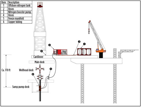
Two well control specialists were dispatched to the location for a site inspection. Measurements were taken, and it was determined that an ice plug could be placed in the area below the casing spool and just above the damaged 10¾-in. casing top, Fig. 1. The bottom of the ice plug would cover the very top of the 10¾-in. casing, however the plug would have to be formed through the 20-in. drive pipe and across the 16-in. surface casing.
CHALLENGES
Challenges were noted immediately during the initial site visit. The first challenge was placement of the ice plug, which would be below the deck of the platform. This would require good scaffolding operations, to allow a platform to be constructed in the desired area.
The top of the 20-in. casing would have to be hot tapped to circulate a freezable fluid, and to monitor for a pressure build-up in the casing. A previous hole had been tapped at the level of the plus 10 deck. The fluid would be pumped into the lower hole and exit the top hole. During an injection test, the 16-in. × 20-in. casing was found to be cemented. Although this situation was not part of the original planning, it was not considered critical to forward operations; cement has a reasonably good thermal conductivity but it does delay the initial freeze time.
Another challenge was the size of the casing strings to be frozen. With 20-in. drive pipe and the time frame involved, it was considered to be a large job. The length of time that the plug would be in place would also pose a challenge, with an estimated 24 to 36 hr for the BOP stack to be changed out.
However, the biggest challenge would be the distance between the nitrogen storage tanks and the wellhead, where the freeze was to take place. An ice plug 5 ft in length was deemed necessary for this plug and to create it, two separate lengths of 150 ft of copper tubing were tightly coiled around the 20-in. casing, across the area where the 10¾-in. casing was missing. Owing to space limitations on the platform, the nitrogen tanks had to be placed on the cantilever of the jackup, some 180 ft away.
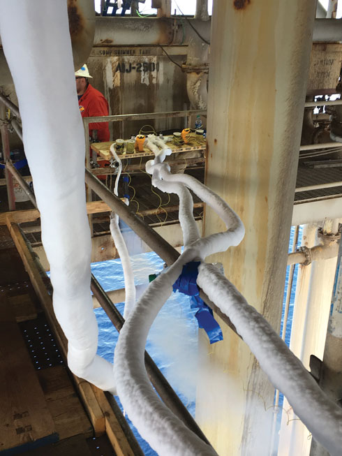
Approximately 75 ft of this length was vertical. To deliver the nitrogen, the commonly sized line connected the nitrogen tanks with the manifold near the wellhead, however the distance involved was far more than common practice, Fig. 2.
JOB EXECUTION
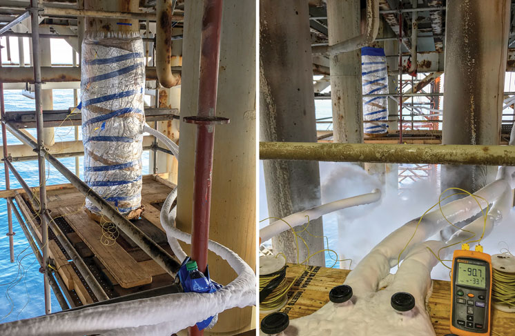
A 24-bbl mixture of bentonite and fresh water was prepared, and the drill pipe was run to the top of the damaged 10¾-in casing. Next, 20 bbl of the gel mixture were pumped down the drill pipe, which was subsequently pulled out, and the blind rams were closed to allow a slight positive pressure to help impede gas migration. Nitrogen storage tanks were pressured up to 30 psi, which is typical on such procedures, and liquid nitrogen was sent from the tanks down the 180-ft line and around the 300 ft of copper tubing coiled around the casing, Fig. 3.
Initial results were unsatisfactory, owing to the inability to supply a sufficient quantity of liquid nitrogen to the manifold. This was due mainly to thermal exchange from the tubing over the distance between the nitrogen tanks and the wellhead. Despite the difference in elevation, the tanks situated at a greater height did not help the delivery time as first expected.
It was determined that a booster pump should be able to move fluid at a faster rate and possibly alleviate the situation of the liquid nitrogen changing to gas before arrival at the wellhead area. Conversations with nitrogen experts from different companies were held and opinions ranged from “it was simply not possible due to the distance involved” to “the line diameter needed to be even larger.”
In the meantime, an additional nitrogen booster pump was introduced, and the insulation on the transfer line was improved. The freeze process recommenced and produced satisfactory initial results, but during operations, some issues were noted in keeping the booster units primed.
At the insistence of the nitrogen delivery company, a larger line was installed, but this proved to be unsuccessful, resulting in nitrogen arriving at an even lower level of liquid and quantities being severely depleted. The booster pump priming issue was due mainly to attempting to refill the tank while simultaneously it was being used to supply nitrogen.
The original supply line was used, and operations continued. Although there were issues during the heat of the day, they were managed by changing flowrates and pressures to adapt to the changing diurnal temperatures. The plug began to form in 24 hr and had fully formed in 36 hr, although operations were suspended until daylight.
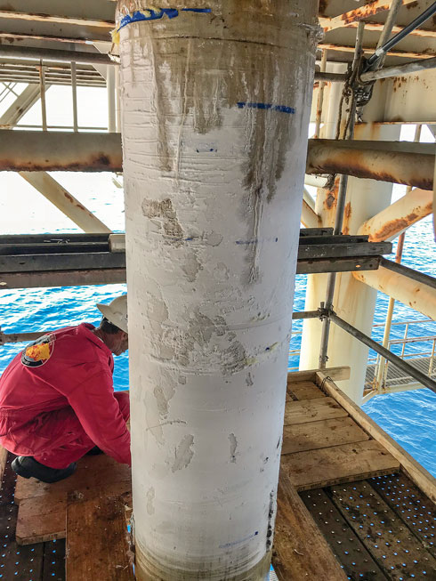
With the well frozen, the plug was pressure tested to 400 psi, which was 220 psi greater than the last recorded wellhead pressure of approximately 180 psi. After a successful test, the pressure was bled off and the blind rams opened. Since no bubbles were detected, operations to change out the BOP stack commenced, Fig. 4. Nitrogen supply to the wellhead continued during the BOP stack change-out.
NEW EQUIPMENT INSTALLED
After installation of the 20-in. diverter package, the newly installed equipment was tested against the ice plug to 200 psi, but it was not bled off to prevent any sudden movements of the plug during thawing. During the BOP change-out, a second smaller-diameter supply line was rigged up directly from the nitrogen tank to the freeze manifold, to test a theory.
The tank was originally pressured up to 30 psi, but the smaller line proved capable of delivering an ample supply of liquid with a tank pressure that could be lowered to 20 psi. It is believed that this line diameter would be usable from a hot start, even with the smaller line diameter.
RESULTS
The job proved to be difficult from the beginning. Firstly, nitrogen transfer experts insisted, and normal operating procedures suggested, that the distance involved was too great to adequately freeze through the casing strings. Nonetheless, the Boots & Coots experts decided that with a correctly engineered solution, it would be possible.
A working formula, involving a precise pump rate and correct volumetric feed from the nitrogen tanks, led to the creation of an ice plug barrier within the casing, with sufficient reliability to allow the BOP stack to be removed. After a pressure test, the BOP stack and casing spool, complete with the top section of the 10¾-in. casing, were removed and a diverter stack was installed.
Nitrogen continued to be pumped throughout the entire diverter installation process and despite the distance involved, the ice plug was maintained. The diverter was tested successfully to 200 psi before the freeze equipment was rigged down, completing the operation. Three different line diameters were employed during this project, with varying success.
The time that it took to deliver liquid nitrogen from the tanks to the wellhead was deemed the main issue and was dealt with accordingly. The company’s well control specialists engineered a unique solution, resulting in a successful nitrogen freeze operation on a well that the experts said was virtually impossible to achieve. ![]()
- Applying ultra-deep LWD resistivity technology successfully in a SAGD operation (May 2019)
- Adoption of wireless intelligent completions advances (May 2019)
- Majors double down as takeaway crunch eases (April 2019)
- What’s new in well logging and formation evaluation (April 2019)
- Qualification of a 20,000-psi subsea BOP: A collaborative approach (February 2019)
- ConocoPhillips’ Greg Leveille sees rapid trajectory of technical advancement continuing (February 2019)

