Inflatables solve a multitude of downhole restriction issues
One of the first uses of inflatable packers was while cementing during the well construction phase. The inflatable element was mounted on casing and used as a base for secondary or off-bottom cement jobs. This is still a common use of inflatable tools. During a well’s producing life, inflatable tools are often used while servicing a well, when a downhole restriction is present that excludes the use of a mechanical bridge plug or packer. For example, inflatable elements can be passed through production tubing on wireline to perform a plug-back, or they can be used with coiled tubing to perform a thru-tubing squeeze job. The thru-tubing operation is preferable; otherwise, operators have to kill the well to perform an intervention. Inflatable tools are also well-suited for use in open-hole barefoot completions, when well testing or water shutoff is required. For offshore wells, where section milling is often needed during P&A operations, inflatable tools are ideal.
WHAT IS AN INFLATABLE TOOL?
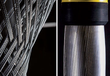
The critical component of any inflatable tool is the inflation element. The basic components of an inflation element are the inner bladder, the support structure, and the elastomer cover. The inner bladder expands and contains the inflation fluid. Outside of the inner bladder is the reinforcement or support structure, which can be made of cable, stainless steel slats, or a combination of the two, Fig. 1.
Outside the support structure is the elastomer cover, which creates the hydraulic seal. The choice of which of the two reinforcement designs to use - a weave support made of cable or a stainless steel slat support - depends on the application. The inflation element with the weave reinforcement is best-suited for open-hole applications, where its exceptional multi-set capability and easy conformance to irregular borehole shapes offer a distinct advantage.
For cased-hole applications, the stainless steel slat reinforcement is preferred, because a portion of the fortification can be exposed to achieve anchoring. The element is anchored through the friction force generated in the contact area of the exposed slats, once the internal inflation pressure is applied.
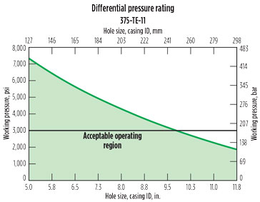
The inflation element’s expansion ratio is determined by the inflation element type and the well conditions. The weave elements have an expansion ratio of 2:1, which means a 4¼-in. OD element can inflate to 8½-in. The slat element can achieve an expansion ratio of 3:1, so that a 21/8-in. OD element can inflate to 63/8-in. The differential pressure rating of an inflation element is dependent on two main factors: the expansion ratio and the temperature at the setting depth. As expansion ratio and temperature increase, the differential pressure rating decreases, Fig. 2.
The choice among the different sizes of inflation elements depends on the type of tool. For service tools, inflation elements start at 1.69 in. and go up to 15-in. For casing annulus packers (packers manufactured onto casing), the sizes start at 23/8-in. and go up to 30-in. The type of application determines the type of tool that the inflation element is placed on.
The basic service tool components are a control sub equipped with an inflation mechanism, a packer mandrel, the inflation element, and a release mechanism to unset the packer if retrieval is required. The inflation mechanism is designed with different options, depending on the deployment method and application. For example, wireline deployment versus drill pipe or coiled tubing, application requirements for a single set versus multiple sets, and vertical or deviated (including horizontal) well geometry.
For most single-set bridge plug applications, a ball is used to initiate inflation by landing on a ball seat inside the control sub. Once the ball is on seat, fluid is diverted into the inflation element. When the designed inflation pressure for an application is reached, the inflation mechanism will lock in the inflation pressure. To release from the set bridge plug, a hydraulic or mechanical release mechanism can be used, depending on the deployment method.
For applications that require pumping through the tool, a packer configuration is used. The basic components are the same as in the bridge plug, but there are more options available for the inflation mechanism. A ball can be dropped in instances where the packer is required to be set only once, such as for a cement squeeze job. For multi-set operations, an auto piston device is available, where no ball is required. Operators simply apply pressure to the tubing, which causes the packer to inflate. Once the inflation element is set, slacking off weight on the device will lock in the pressure and allow flow to resume through the tool. This type of configuration is common when treating with acids or solvents, with a fluid control device run above the packer.
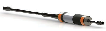
A straddle is created by adding a lower packer, Fig. 3. Two packers can be run together, separated by tubing with perforated pup joints, to allow selective isolation pumping into a formation or flow testing a formation. The packer spacing can be as close as 10 ft apart, or as far as hundreds of feet apart, if required for the application. Single-set options in straddles also can be configured, if a scab liner is required to shut off water flow.
Inflatable service tools can be deployed on drill pipe, tubing, coiled tubing, or wireline/slickline. The tool configuration chosen is based on the conveyance method. For applications where deployment is on wireline or slickline, a battery-operated inflation tool is run to inflate and set the plug or packer. This method is attractive due to its low cost, compared with using a rig or a coiled tubing unit. For single-well offshore platforms, running on a slick line may be the only option, because of limited deck space.
CASING ANNULUS PACKER
A casing annulus packer (CAP) is manufactured onto a joint of standard API casing. The components of a CAP include a valve sleeve (which is fixed to the OD of the casing), the inflation element, and a sliding end. During inflation, one end of the packer slides to allow the OD to increase. The most common CAP application is for secondary cementing or off-bottom cementing, where a stage tool or cementing port collar is placed above the CAP to allow the pumping of cement to the surface. The CAP is often used on intermediate casing strings, when it is not possible to get cement to the surface, due to low bottomhole pressure.
These wellbore sections are typically drilled fast and not calipered, and therefore large wash-outs are common. While every effort is made to place the packer in a gauged section, sometimes the packer is set in a washout, which may result in over-expansion, causing the inflation element to rupture. Furthermore, if the annulus is on losses, regaining casing integrity can be difficult, because there is more hydrostatic pressure at the CAP on the ID of the casing than on the annulus. The valve sleeve is designed to lock-out in the event of a rupture, but an overbalance scenario can prevent this. While experience shows that this is a low-frequency event, the possibility of an occurrence requires a solution.
To address the inability to shut the valve, in the described unbalanced scenario, a new valve design was required to protect against this scenario.
New shut-in valve. To solve the issue, new technology was incorporated into the valve sleeve to provide redundancy, to ensure casing integrity is maintained once the packer is set, no matter the fluid level in the annulus. The technology is patent-pending and available in any size of casing annulus packer. Field trials have been successful in the Permian basin, in wells with 9 5/8-in. intermediate casing. In the Permian basin, and in other applications, it is common to have a low fluid level in the annulus, or for the annulus to be on losses in the intermediate casing section.
The basic operation for a two-stage cement job is to pump the primary cement job through the float shoe. Then, the wiper dart lands on the float collar and pressure is increased to inflate the CAP. After the CAP is set, additional pressure is applied to open a stage tool. Following, an opening plug is dropped. The second stage job is then pumped and a closing plug lands on the stage tool to close it. In the event of a ruptured packer, the new valve sub is activated to ensure casing integrity. The contingency plan at this point is typically to wait a few hours for the cement to setup on the primary job before opening the stage tool to pump the secondary job.
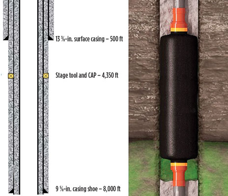
Figure 4 shows a typical construction for an intermediate section in a Permian well with an 8½-in. horizontal section below the 9 5/8-in. shoe. The CAP has a 10 ft seal with a stage tool on top. The packer was inflated as designed and the secondary cement job was successfully pumped. The service provider’s new technology ensures that in the unlikely event of a ruptured packer, casing integrity can be immediately reestablished by activating the new valve system.
THRU-TUBING WIRELINE INTERVENTION
An inflatable bridge plug or packer can be set using wireline or slickline. A battery operated system is used to deploy and set the tool. Downhole electronics are used to control the inflation process through a motor/pump assembly. Depending on how critical an exact setting depth is to operational success, the operator can use a wireline or a slickline. For applications where the setting depth is critical, wireline is used because it can run a gamma ray and casing collar locator for correlation prior to setting the tool.
A solution may require either a bridge plug configuration or a packer configuration. In the case of a packer, the application is typically to use a scab liner to isolate a section of the wellbore. A recent case history required such an approach. A well in deep water experienced pressure on the “A” annulus and regulators required the operator to locate and repair the leak. It was determined that an isolation packer was leaking. One option would have been to mobilize a rig and pull the upper completion to replace the isolation packer.
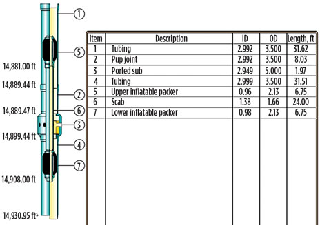
But this was an older well producing at low flowrates (1,500 bpd), so an expensive intervention with a rig was considered uneconomical. A rig-less operation therefore was considered using inflatable packers deployed on a wireline system, Fig. 5. Inflatable technology was chosen because a restriction in the completion would not allow conventional mechanical packers to pass. The leaking isolation packer was positioned above a ported sub. The proposed plan was to set a packer below the ported sub on one run, and then set an upper packer equipped with a blank interval of pipe beneath it, to “sting” into the top of the lower packer. This would isolate the ported sub while allowing flow through the scab assembly.
The upper packer assembly was designed to sting into a polished bore receptacle (PBR) that had been left looking up after the lower packer was set. The upper packer assembly was then latched into the PBR. Shear pins in the latching mechanism allowed this assembly to be retrievable. In this case, the packers were set successfully. Once the scab liner was in place, the well was put back on-line and slowly ramped up to the previous 1,500 bpd production rate. No pressure was seen on the “A” annulus meeting the regulator requirements. This intervention was done at approximately 5% of the estimated cost of a rig-based solution. The expandable remedy is ideal for offshore developments that are in the later stages of production, where flow rates and pressures have been reduced.
MEASURING IN-SITU OPEN-HOLE STRESS
Knowing the in-situ stress of an open-hole section is desirable for several reasons. Firstly, stress values are crucial to managing an injection well to ensure that the injection zone maintains integrity with respect to cap rock strength and that no fractures are created that would allow injection fluids to go out-of-zone. In-situ stress measurements also help engineers select optimal casing shoe depths. Drilling teams are typically conservative when planning casing shoe depths when there is limited information or predictive modeling is used. However, setting casing early may drive-up well cost, or conversely, estimations may be aggressive which could lead to well control issues and implementing costly contingency plans.
The typical method used to measure in-situ stress is a wireline deployed formation testing tool. However, in wells with angles of more than 30° challenges arise due to the small volume of available hydraulic energy, which may not be sufficient for a wireline formation tester to gain accurate measurements.
Inflatable alternative. The use of an open-hole inflatable packer, equipped with pressure gauges, is a proven alternative to wireline formation testing tools. Using an inflatable open-hole packer allows access to unlimited hydraulic energy to perform the test since fluid is being pumped from surface. While this operation has a higher cost and poses greater risk, these must be weighed against the cost of the uncertainty in estimating stress.
Operators have successfully used open-hole inflatable packers to measure in-situ stress. Experience has shown that when office and rig personnel conduct detailed job planning, execution of the operation is successful. In two recent cases, companies working in an offshore environment used open-hole inflatable packers to isolate and measure in-situ stress.
Measurements were made in one case with a straddle configuration using two packers. This type of set-up enables engineers to determine exactly where the measurement was taken as opposed to when only one packer is deployed. The purpose of the test was to measure the in-situ stress to manage the injection pressure through the life of the well. The basic operation in measuring in-situ stress with an inflatable packer is to pressure up and initiate a fracture by injecting fluid into the formation while maintaining a constant injection rate. The fracture propagation pressure and closure pressure thus obtained are then used to determine the stress measurement. This test is typically repeated three times for each setting depth.
Single packer case history. The same process of propagating a fracture and then measuring the closure pressure was performed using a single packer configuration. However, with a single packer there is no way to determine at what depth below the packer the fracture was initiated. For some operators, the reduced risk of running one packer, rather than two, is more advantageous than the greater accuracy that comes from isolating an interval. This operator used a single packer approach in a deepwater application to successfully measure in-situ stress, deriving enough usable data to accurately predict the next casing point. The simplified operation generated substantial cost savings by eliminating an additional drilling liner compared to stress estimations used on previous wells.
HIGH EXPANSION ELEMENT
Deepwater plugging and abandonment (P&A) operations commonly use coiled tubing to deploy various services required in pre-abandonment procedures. In some instances, the BOP riser package for coiled tubing units can have an ID smaller than the ID of the pipe where an operation is to be performed. This restriction typically requires the use of a high expansion inflation element. Pre-abandonment work is often done to isolate production zones prior to moving in a rig to perform the full P&A procedure. Doing pre-abandonment work with a coiled tubing unit is cost effective and operationally safe. Doing the initial work on coiled tubing further allows complete well control to be maintained since the work is conducted through the existing wellhead.
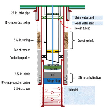
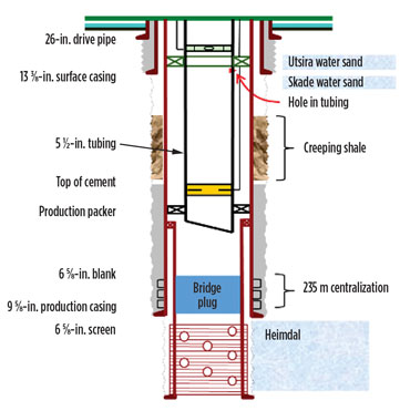
Case study. A multi-well campaign was planned and required a bridge-plug be set above screens and cement dumped on top. The casing to set the bridge-plug in was 6 5/8-in. with 5½-in. tubing above, Fig. 6. A 3¾-in. inflatable element was selected based on the minimum restriction in the 5½-in. tubing. The packer was deployed to depth, and pressure was applied to inflate and set the plug, Fig. 7. A hydraulic disconnect was used to release the tool from the plug, after which cement was spotted on top of the plug.
Once the cement had set, a pressure test was performed to assess the integrity of the plug. This typically was done by applying pressure at the surface. However, in some wells pressure integrity was lacking above the cemented bridge plug. In these cases, a multi-set packer with a 2.90-in. OD was run in the well to set just above the bridge-plug, to perform a pressure test.
Results. In all, 16 wells were successfully pre-abandoned, using inflatable plugs run on coiled tubing. Much of the success of this project was due to the detailed pre-job planning. While engineers have good intentions, in many cases not all stakeholders are included in the planning process. It is important to include platform workers, coiled tubing operators, and the actual service personnel responsible for running inflatable tools. Their input can highlight important details and identify critical contingencies. It is wise to “measure twice and cut once,” in this type of multi-well campaign.
CONCLUSION
Inflatable tool design has improved significantly over the past 20 years, and research and development is ongoing to extend the limits of the technology. These new inflatable tools provide operators with a cost-effective alternative method when a conventional approach is not possible. The primary reason for selecting an inflatable tool is to circumvent a wellbore restriction that prevents the use of a standard oilfield tool. Other reasons are to safeguard weak and/or corroded casing that might be damaged using standard methods. Inflatables also have the capability to retrieve a tool through a restriction, and efficiently handle large casing sizes where conventional tools may be in low supply or non-existent. ![]()

