Part 2 of 3: Leaching a thin layer at the working surface of a PDC cutter to remove the cobalt dramatically reduces diamond degradation due to frictional heat.
Federico Bellin, Alfazazi Dourfaye, William King and Mike Thigpen, Varel International
The first installment of this three-part series discussed the early commercial history and technical challenges encountered in the manufacture of polycrystalline diamond compact (PDC) cutters and bits. One major challenge discussed was a high degree of thermal wear experienced by these cutters. This second article discusses in depth one solution that has been applied to raise the resistance of PDC cutters to thermal wear. This is followed by an in-depth review of how PDC cutters are tested and qualified.
PDC CUTTER LEACHING
As stated in the first installment of this series, PDC cutters usually use cobalt as a binder for the diamond grit. Cobalt acts as a catalyst during the ultra-high-pressure sintering of the PDC. It is believed that this catalytic effect creates the diamond-to-diamond bonds and unitizes the diamond layer to the tungsten carbide substrate. The result is a tough and abrasion-resistant cutting edge suitable for oilfield use.
High thermal wear. However, the diamond compacts have limited heat resistance. At atmospheric pressure, a diamond’s surface turns to graphite at 900°C or higher. In a vacuum or in inert gas, diamond does not graphitize easily, even at 1,400°C. But during use, conventional PDC cutters experience a decline in tool performance around 750°C, which the cutting edge can easily reach due to frictional heating in hard, abrasive rock. Flash temperatures, which are extremely high localized temperatures at the microscopic level, can be much higher, far exceeding the melting temperature of cobalt (1,495°C).
The presence of cobalt is believed to be the reason that PDC converts to graphite at a lower temperature than simple diamond. As temperatures increase, graphitization of the diamond in the presence of cobalt becomes a dominant effect. Diamond wear is then due to an allotropic transformation into graphite or amorphous carbon under the influence of localized frictional heating. This transformation is accelerated in the presence of cobalt through a combination of mechanical and chemical effects. For one thing, the shear resistance of the cobalt drops rapidly, and the grains are not strongly held. It is also known that the real area of contact depends on the velocity with which plastic strains are propagated in the metal binder. The shearing occurs so rapidly that full plastic yielding under the normal load is not possible.
In addition, there is a significant difference between the thermal expansion coefficients of cobalt and diamond. During heating, cobalt expands at a higher rate than diamond. The amount of thermal stress in the diamond table increases, and the structure breaks down. The cobalt between the diamond crystals expands and breaks the diamond-to-diamond bonds.
As a means of improving PDC heat resistance, polycrystalline diamonds have been created that are not bound to ultra-hard alloy base materials. These are then immersed in acid and heat treated. The acid treatment dissolves the metal binder phase in the polycrystalline diamond. This process creates a thermally stable polycrystalline (TSP) that withstands temperatures of up to 1,200°C.
However, the material created by this process has additional problems. With the cobalt phase removed, cavities remain in the TSP, degrading the strength of the sintered material. The result is a material that lacks sufficient hardness and impact strength to be used as a cutting tool. Without the cobalt phase, it is difficult to create a strong bond between the TSP and the tool.
Thermally stable layer. A PDC material was engineered to resolve the temperature deficiencies of conventional PDC material without the mechanical strength and attachment deficiencies of TSP. When using PDC as a drilling tool, the part that becomes hottest is the cutting tip that comes into contact with the formation. The temperature decline as distance increases from the point of contact is considerable. Cutting tool studies in the late 1950s found that the temperature a few microns from the contact point is about 12% of the (absolute) temperature at the point of contact. Since the temperature decreases very rapidly with increasing distance from the shearing zone, the cutting tip behaves like a thin film of low shear strength supported by a hard substrate. Therefore, improving the heat resistance of just the cutting edge of a PDC would significantly improve drilling performance.
The new PDC has a conventional diamond table with a surface layer from which the cobalt has been removed. After finishing the PDC conventionally, its cutting surfaces are exposed to powerful acids that remove the cobalt phase though an acid etching process called leaching. The cobalt is removed up to 200 microns deep into the polycrystalline diamond.
Leaching a thin layer at the working surface dramatically reduces diamond degradation and improves the tool’s thermal resistance. First, without the cobalt in the high-temperature area (i.e., the cutter tip), the diamond-to-diamond bonds remain strong despite the shearing phenomena described above, so little graphitization occurs. Second, because the leached layer is now composed of diamond alone, it transmits heat away from the cutting tip more efficiently.
Because the cobalt phase remains inside the PDC diamond table, there is less loss of overall strength in the sintered object than occurs in TSP. Also, because there are no interior cavities, the thermal conductivity does not decline in the diamond table. The heat that is generated at the tip of the tool is effectively dispersed.
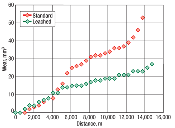
Two PDC cutters—identical except for the leached cutting surface in one—were subjected to a heavy wear test, Fig. 1. After cutting about 5,000 m of rock, the rate of wear in the unleached cutter began to increase dramatically. The leached PDC cutter, in contrast, maintained a relatively constant rate of wear for about 15,000 m of cutting.
 |
|
Fig. 1. Wear for leached and non-leached cutters subjected to a heavy wear test.
|
|
TESTING AND QUALIFICATION
PDC cutter testing methods can be broken down into two categories: In destructive testing, the cutter is destroyed and cannot be reused. These testing methods intend to simulate downhole conditions as closely as possible to assess how the cutter will behave under these conditions. Consequently, only samples of parts are tested and the consistency of the batch is assumed. There are two main types of destructive tests: abrasion and impact.
Non-destructive testing is used by quality assurance teams and is applicable to 100% of the individual cutters since the cutters are not destroyed. However, in some cases a special preparation of a part is needed and the part cannot be used again.
Abrasion testing. Abrasion resistance is the ability of the cutter to survive under abrasive conditions that are mainly driven by the rock strength and the hardness of the minerals in the rock. Therefore, all abrasion tests are conducted with hard rocks that contain minerals like quartz, such as granite or quartzite.
Within the drill bit industry, abrasion tests are conducted by driving a cutter set with a given back rake angle against the rock while indenting the rock with a given depth of cut. The rake angle and the depth of cut may differ from one company to the next. There are three types of machines used for abrasion testing, and the pertinence of the results is heavily dependent on the type of test method.
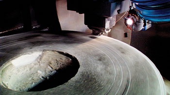
Vertical turret lathe (VTL). This is the test method most commonly used by major cutter providers, Fig. 2. The cutter is fixed on a VTL, which has a rock sample (usually granite) positioned adjacent to the cutter. The rock is then rotated around the VTL’s axis of rotation at a given speed that may vary based on the level of energy for which the cutter is being tested. The cutter is then pushed to indent the rock at a given depth of cut that may vary from one test to another. However, in the case of granite, this depth of cut is less than 1 mm. The cutter moves laterally from the outer circumference to the axis of rotation, describing a spiral. The lateral feed rate is then adjusted to ensure an overlap between the two consecutive grooves. Recent VTLs use computed numerical control, and the rotational velocity can be increased or decreased as the cutter moves laterally to the rotation axis to ensure a relatively constant linear velocity. The advantage of VTL testing is its capacity to submit the cutter to very high level of energy, which makes it well suited to the ranking of cutters in highly demanding applications.
 |
|
Fig. 2. Abrasion testing of a PDC cutter with a vertical turret lathe. Courtesy of US Synthetic.
|
|
This test can be performed either dry or wet. In a “VTL dry” test, the cutter is not cooled while cutting the rock, so almost all of the frictional heat goes into the cutter and diamond graphitization is accelerated. This test is well suited to the ranking of cutters that will cut rock under high weight on bit and/or high rotational speed.
The VTL dry test evaluates high-temperature thermal stability and performance of a PDC cutter, and the cutter is tested until the wear progresses into the tungsten carbide substrate. The temperature increase is accelerated when the carbide begins to wear; the test is stopped at the point when the cutter is overheated resulting in diamond graphitization, as indicated by a black ring left on the rock.
The “VTL wet” or “VTL cooled” test is performed to assess cutter life under moderate heat conditions by cooling down the cutter during the test with either water or air. The main source of wear, therefore, is the abrasiveness of the rock rather than thermal factors. The test measures the ability of the diamond grains to resist micro-chipping and gouging by a hard mineral like quartz. The VTL wet test is performed under low depth of cut and low linear velocity. However, at the microscopic scale the cutter is submitted to flash temperatures. The wear due to these localized high temperatures is reduced mainly by the sinking of the heat at the cutter tip by the cooler.
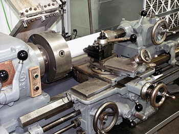
Turret lathe or granite log. Like the VTL method, this test is also performed with granite, but a conventional turret lathe is used instead of a vertical lathe, Fig. 3. The principle is identical to that of the VTL test except that the sliding distance is very limited and only the diamond will be worn. The results are similar to the early wear results of VTL cooled. The test duration is a few minutes, and the thermal impact of the granite-cutter interaction is very limited.
 |
|
Fig. 3. Granite log abrasion testing of a PDC cutter. Courtesy of Dennis Tool.
|
|
Granite log testing parameters may vary slightly by PDC cutter manufacturer. For example, US Synthetic and Diamond Innovations do not use exactly same test parameters, but do use the same granite material for testing purposes, Sierra Granite (a coarse- to medium-grained crystalline igneous with very low porosity and a compressive strength of 190 MPa) or equivalent.
Grinding wheel. This third type of abrasion test has very limited use and consists of abrading a standard silicon carbide grinding wheel with a PDC cutter. Once again, the test is performed during a very short period of time, and the thermal impact is very limited. Wear is measured by the weight lost by the cutter.
G-ratio. In the case of VTL, the wear (weight or volume) is plotted against the distance and the cutter is selected based on the sliding distance at end of the test. The end-of-test criteria vary from one company to another, but all the tests include the wear of the diamond table and of some or all of the substrate.
In the case of granite log test or grinding wheel test, only the final wear (diamond weight lost) is recorded and the operative ratio is volume of rock cut to weight lost. This ratio is generally called the grinding ratio or G-ratio, a cross-industry term used to quantify the resistance of a material to abrasive wear. In the context of PDC cutters, the G-ratio is a dimensionless number that indicates the volume of rock removed for a unit volume of cutter’s material wear. A larger G-ratio indicates that a greater amount of rock will be removed for a certain amount of volumetric wear to the PDC cutter. The G-ratio is expressed as this ratio divided by 1 million; thus, if one unit volume of abrasive bit wear occurs in the process of removing 10 million units of rock, the G-ratio is 10.
The first-generation PDC cutter by US Synthetic had a G-ratio of 1. Modern PDC cutters typically have G-ratios in the range of 15, indicating that abrasion resistance has increased by a whole order of magnitude since the introduction of the first cutters.
Criticisms. It should be noted that the use of the natural rock sample itself has issues that must be considered. For example, the heterogeneous nature of the rock fabric may yield differing results for similar tests (due to macroscopic mineralogical variations, planes of weakness, etc.). In addition, although the use of a crystalline igneous rock sample has been adopted as a standard for testing purposes, this rock may not be considered representative of the rock types normally encountered during oil and gas drilling.
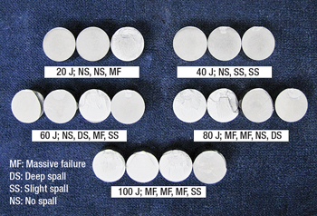
Impact testing. The impact test, or drop test, consists of vertically impacting the diamond table of a cutter inclined at a given angle that may vary from 15° to 25° with a mass dropped a given height. The weight of the mass and the height indicate the level of impact energy to which the cutter is submitted. The level of energy is progressively increased up to 100 J. Each cutter is dropped three to seven times or until it cannot be tested further. Generally, at least 10 samples of a cutter type are tested at each energy level. Because the cutters will have a range of resistance to impact, the test result plotted at each energy level is the average of the area of spalling diamond for each cutter after impact, Fig. 4.
 |
|
Fig. 4. Spalled cutters resulting from impact testing. Courtesy of US Synthetic.
|
|
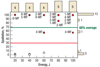
Drop test results can be shown as a function of the remaining or removed diamond table after the test. Figure 5 shows the results of a series of four cutters tested at 20-J increments up to 60 J and a series of five cutters tested at 80 J and 100 J. Of the 22 cutters that were tested, only six survived the test (exhibiting 0% spallation), two cutters exhibited 60% spallation and 14 had more than 80% spallation. The overall average spallation percentage was 68%. In this case, the selection criterion is a spallation percentage lower than 30%; thus, the cutter did not pass the test.
 |
|
Fig. 5. Spallation chart used to plot impact testing results. Courtesy of US Synthetic.
|
|
The challenge of the drop test is correlating the results to actual field conditions. The frequency of the impacts is too few, less than 1 Hz (one impact per second), whereas drillstring simulations have shown axial and torsional vibrations with frequencies ranging 2–6 Hz. The drop test is more useful in providing information on the quality of the diamond table and the diamond-to-substrate interface.
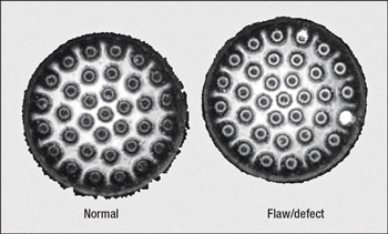
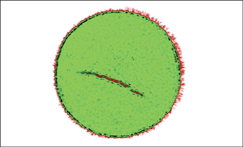
Non-destructive testing. The most widely used non-destructive technique (besides visual and microscopic inspection) is the C-scan, which detects delaminations and voids in the diamond table using ultrasonic waves (0.2–800 MHz). C-scan allows detection of small flaws and estimation of their location and size. The C-scan results are presented in a plane view of the location and size of test specimen features. The plane of the image is parallel to the scan pattern of the transducer. Consequently, results are heavily dependent on surface conditions and the grain size of the diamond table.
To run the test, the cutter is placed in a tank of water and scanned with a scanning acoustic microscope. The ultrasonic source emits a signal into the face of the diamond table and produces an image of the inner diamond table and the diamond-to-substrate interface. The method can help to identify cutter flaws that cannot be discovered through visual or microscopic inspection, Fig. 6. Another advantage of the C-scan is ability to detect the effects of the residual stresses that are estimated using finite-element analysis (FEA).
|
|
|
Fig. 6. C-scans of flawed diamond-to-carbide interface. Courtesy of US Synthetic (top) and Dennis Tool (bottom).
|
|
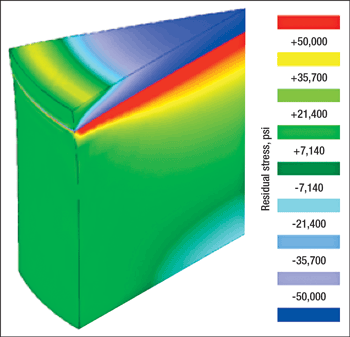
FEA is modeling performed, in PDC applications, on a virtual cutter to simulate the sintering conditions and to predict stress distribution in the diamond table and the diamond-to-substrate interface—especially the residual tensile stress responsible for fragility in the diamond table, Fig. 7. The use of FEA helps to create a numerical matrix solution, mapping the physical properties such as stress and strain of the material at various locations within the cutter. The stress and strain can then be optimized using specific design features built into the cutter. The use of integrated design and FEA has allowed the development of new cutter technologies with improved performance and identified a critical diamond table thickness: 2–3.5 mm contingent upon the diamond grain size and the design features of the interface.
 |
|
Fig. 7. FEA simulation results showing the stress distribution at the diamond-to-substrate interface. Courtesy of US Synthetic.
|
|
FINAL INSTALLMENT
Part 3 of this series will discuss PDC cutter selection for various bit applications. Future PDC developments will also be discussed, including enhanced substrate properties and cobalt management, alternative diamond manufacturing methods, and newly developing cutter testing methods. The series will conclude with an overview of PDC bit market growth. 
ACKNOWLEDGMENT
The authors would like to thank Varel International for permission to publish this article series. Thanks also to Diamond Innovations, US Synthetic, Dennis Tool, the Paris School of Mines, the University of Trento, Mike Reese, Crystal Montanez and Brandi Williamson for their efforts in developing the series.
|
THE AUTHORS
|
|
Federico Bellin is a Senior Technology Engineer for Varel International. He has 12 years’ experience in PDC cutter and insert design and is highly experienced in HPHT technology. Mr. Bellin has worked both in Europe and the US cooperating with R&D institutions worldwide to develop new materials and new designs for ultra-HPHT systems. He earned a master’s degree in materials science in 1997 from the University of Trento, Italy.
|
|
|
| Dr. Alfazazi Dourfaye is the Manager of Technology Development for Varel International. He has 20 years of experience in PDC cutter and bit technology including testing development, engineering and software development. Dr. Dourfaye graduated from the Alès School of Mines in 1990 and earned his PhD at the Paris School of Mines in 1995. |
|
|
| William King is the Director of Marketing and Intellectual Property for Varel International. He has 29 years of experience in the drill bit industry, including roles in design, product development, bit applications, international sales, software development, marketing and intellectual property management. Mr. King attended the University of Illinois and the University of Utah. |
|
| Mike Thigpen is a Senior Technology Engineer for Varel International. He has 26 years of experience in the oilfield service industry including roles in design, product development, bit applications and engineering management. Mr. Thigpen earned a BS degree in mechanical engineering from the University of Houston in 1983. |
|


