Simulation workflow for a fractured reservoir aids CO2 flood planning
Existing technology and methods can quantitatively integrate geophysical, geological and engineering data to develop reservoir models for fractured reservoirs. Such a workflow was used to model the Tensleep reservoir in Wyoming.
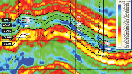
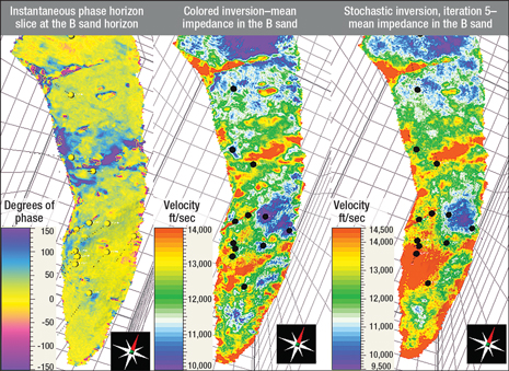
Existing technology and methods can quantitatively integrate geophysical, geological and engineering data to develop reservoir models for fractured reservoirs. Such a workflow was used to model the Tensleep reservoir in Wyoming.Ahmed Ouenes, Prism Seismic; and Tom Anderson, RMOTC Injecting CO2 in hydrocarbon reservoirs is an established enhanced oil recovery (EOR) process that can usually extend an oil field’s production and increase the ultimate oil recovery. Proper planning of a CO2 injection project requires an accurate characterization and simulation of the reservoir, with the goal of optimizing the oil recovery. The presence of faults and fractures in the reservoir complicates this process. Fractures can enhance reservoir permeability and thus allow larger volumes of CO2to be injected. However, these fractures can also create early CO2 breakthroughs in existing wells, or leakage through fractures and non-sealing faults to other formations or even to the surface. The reservoir characterization and simulation must accommodate these complications to ensure a successful result. This article describes a robust characterization and simulation workflow for a fractured reservoir considered for CO2 injection. This workflow has been successfully applied to various oil and gas fields,1–7 and is illustrated using the Tensleep reservoir at the Rocky Mountain Oilfield Testing Center (RMOTC) test site on Teapot Dome oil field in Wyoming. GEOLOGY OF THE TENSLEEP FORMATION Teapot Dome is an asymmetric, doubly plunging Laramide-age anticline located near the southwestern edge of the Powder River Basin in Natrona County, Wyoming. A total of nine productive horizons are present in the field, with the Pennsylvanian Tensleep Formation being the deepest and one of the most prolific producers in the field. The Tensleep Formation has an average gross thickness of 320 ft and consists of eolian sandstones interbedded with sabkha and marine dolomites. The Tensleep reservoir is divided into the A sand, B dolomite, B sand, C1 dolomite and C1 sand. The A and B sands are oil producers; the C1 sand is wet. Core descriptions and image logs indicate that the Tensleep Formation is fractured.8 Most of the fractures and faults at Teapot Dome are interpreted to have formed during deformation associated with the Laramide basement-cored thrusting.9 Well tests indicate high fracture connectivity in the field. The presence of these connected open fractures produces permeability anisotropy, which must be accounted for in the planning of a CO2 injection project. STEP 1—GEOPHYSICAL ANALYSIS The initial geophysical work is familiar to every seismic interpreter: generate synthetic seismograms and correlate them with the seismic data to identify key seismic events and interpret horizons and faults. In addition to the seismic amplitude data, additional seismic attributes such as similarity, volumetric curvature and colored inversion were generated to aid in the structural interpretation. Building reservoir models required a detailed seismic interpretation in the reservoir interval; five key horizons were interpreted in the Tensleep Formation and tied to the formation tops in time, Fig. 1. Spectral imaging attributes such as instantaneous phase and multiple stochastic inversions generated additional seismic attributes for use in building reservoir models and identifying structural features, Fig. 2.
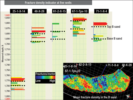
Once the key horizons and faults were interpreted, these objects were used to construct the watertight structural framework in the time domain. In this structural framework, all object intersections (fault-fault intersections and horizon-fault intersections) truncated cleanly, providing the sealed 3D framework necessary for the subsequent work. With the 3D structural framework built, a 3D geocellular grid was generated within this container, dividing the Tensleep reservoir into three zones: A sand/B dolomite with nine layers, B sand with 13 layers, and C sand with three layers. This layering ensured that the cell thickness was about 1 ms in the time domain or 2 m in the depth domain. In the areal direction, the cells were 67 m x 67 m, resulting in a 3D geocellular grid with 376,025 cells. As the seismic bins were rectangular and current reservoir simulators still required orthogonal grids, the derived 3D grid with its rectangular cells and vertical columns was the appropriate bridge to the geology and reservoir engineering domains. The seismic attributes were copied into the 3D geocellular grid, using an appropriate averaging technique, providing the seismic information needed for reservoir modeling. STEP 2—SEQUENTIAL GEOLOGIC MODELING The sequential geologic modeling approach uses multiple seismic attributes as building blocks to estimate, in a sequential manner, related petrophysical properties such as facies, shale volume, porosity, water saturation and permeability. This process is sequential because the first model created is the reservoir property that potentially controls the distribution of most of the other reservoir properties. In this study, the shale volume was chosen as the primary reservoir property. The shale volume model was built using a neural network approach, constrained by many seismic attributes. This shale volume was subsequently used to estimate another reservoir property—density. Density logs were available at nine wells. In addition, the shale volume model and the available seismic attributes were used to generate the density model. It was used, along with the shale volume model, in subsequent modeling. This sequential process similarly estimated other reservoir properties, including log-derived porosity, core porosity, core permeability, and oil saturation estimated from core data. The two particular reservoir properties that required special attention were oil saturation and core permeability. Unlike previous property models, the core permeability model must take into account the effects of fractures, hence the need for adding geomechanical attributes such as slopes, curvatures, deformation and distance to faults. Using the available core permeability data at 11 wells, the previously derived shale volume, density, log and core porosity models, the multiple seismic attributes available in 3D and the computed geomechanical drivers, various core permeability models were estimated and validated. An average core permeability model was derived by combining many realizations. This model did not take into account large-scale effects of fractures and primarily represented the matrix permeability. The final reservoir property required for the simulation was the oil saturation. Given the tilted oil-water contact in the reservoir, this property required special attention. Using the available core oil saturation data at 11 wells, the previously derived shale volume, density, log porosity, core porosity and permeability models, along with the multiple 3D seismic attributes, various core oil saturation models were estimated and validated and an average core oil saturation model was derived by combining many realizations. This average core oil saturation model was used as an input for the reservoir simulation. The only property left to generate was the fracture density, which was used to estimate the effective permeability required for the simulation. STEP 3—FRACTURE MODELING To capture fracture effects at multiple scales and simultaneously integrate the available core, log, seismic and well test data, the continuous fracture modeling (CFM) technique was used to model the Tensleep fractures. The CFM approach does not focus on identifying the fractures themselves but rather on identifying the factors that control where fracturing occurs. Fracture drivers can be identified using seismic data (available over the entire reservoir) as well as borehole data. These fracture drivers are then related to fracture indicators, demonstrating the existence of a fracture at a specific location in a well. The fracture indicators are derived from interpretation of core descriptions, image logs, production logs, etc. Once the relationship between fracture drivers and fracture indicators in the wells is established, the fracture drivers can be used to predict the location of fractures elsewhere in the reservoir. A neural network is used to find possible relationships between the fracture drivers and fracture indicators observed at the wellbore. The neural network approach first ranks all the fracture drivers according to how reliably they correlate with the fracture indicators. The best-correlated fracture drivers that make sense geologically are then subjected to a training and validation process before being used to generate a suite of equiprobable fracture density realizations. These realizations can be screened and calibrated to permeability-thickness data obtained from well tests, if available. The resulting effective permeability model can then be exported for use in numerical simulation and development planning. In the Tensleep reservoir, geophysical, geological and geomechanical drivers described above were available for generating fracture models. The fracture indicator logs were generated from interpreted image logs at five wells, providing fracture density logs (using only open fractures) at these five wells, Fig. 3. Fracture directions recorded in the image logs were not used as input in the CFM approach, and were kept for validation purposes. The computed fracture models provided a 3D distribution of the fracture density.
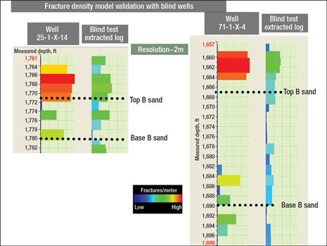
The fracture models were validated using two blind wells. In each test, the blind well was removed from the modeling, and the estimated fracture density at the blind well was extracted from the model and compared to the actual fracture indicator log. For both blind wells, the model was able to reasonably predict the zones of low, medium and high fracture density as shown in Fig. 4.
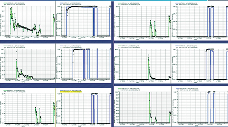
STEP 4—RESERVOIR SIMULATION The ultimate objective of this workflow is to derive dynamic models that are able to reproduce past individual well performances without the need for any time-consuming history matching. This provides an additional validation of the fracture models derived using the CFM approach. Using the reservoir parameter models generated in steps 2 and 3, both black oil and compositional reservoir simulations were run to verify that these models would produce a history match to the production data. Black oil reservoir simulation. In a black oil simulator, where the two main fluid phases considered are oil and water, the complex reservoir effects related to the injection of CO2 were not considered. In the case of the Tensleep reservoir, CO2 injection did not yet occur and therefore the reservoir model could be validated with a black oil model. The aspects related to CO2 injection will be considered in the next section using a compositional simulator. The three major reservoir properties that are needed to carry out reservoir simulation are permeability, porosity and oil saturation. Given the presence of fractures with high connectivity, the matrix permeability was expected to be enhanced. The degree of this permeability enhancement depends on the fracture density. Given the extensive fracturing that was present in the Tensleep Formation, there was no evidence of a dual-porosity or dual-permeability medium, and the reservoir appeared to behave as a single-porosity medium with an enhanced effective permeability. The matrix porosity seemed to provide the storage for the oil, which had a tilted oil-water contact. Water production rates indicated that the Tensleep Formation had a strong aquifer, resulting in a pressure drop of less than 100 psi throughout the formation. Consequently, water drive was considered the primary producing mechanism in the reservoir. Initial water saturations (Swi) were between 12.5% to 22.1%, and residual oil saturations (Sro) were between 28.7% and 56.3%. Measurements and tests of the Tensleep Formation showed that the initial reservoir pressure at a depth of 5,400 ft is about 2,350 psia at a temperature of 190°F. Analysis of producing wells in the Tensleep Formation showed that all of the production occurs near the crest of the structure. Oil producing wells exhibit a fairly good production history for the first two years, followed by a rapid breakthrough of water. At that point, the oil production is replaced by a high rate of water production, which confirms very high mobility of water in the reservoir. The dynamic model uses the derived matrix porosity and oil saturation as input in the reservoir simulator. The key reservoir property was the effective permeability, as the dynamic model used a single porosity system. In this case, the reservoir permeability was simply the effective permeability computed as follows: Keff = Km + C • f where is effective permeability of the combined matrix and fracture flow in millidarcies, is matrix permeability in millidarcies,is fracture density (number of fractures per meter), and C is the scaling factor to be estimated by history matching. The matrix permeability and fracture density were estimated in the previous steps, and the scaling factor was estimated during the history matching process. The history matching process consisted of finding three reservoir parameters that were unknown: 1) the scaling factor C, required to compute the effective permeability, 2) the relative permeability curves, and 3) the strength of the aquifer. After a few tests, these three unknowns were easily estimated and the individual well performances of all the wells were matched as shown in Fig. 5. The dynamic model allowed a better understanding of the current fluid distribution, which in the case of Teapot Dome showed that the strong aquifer is pushing the oil from the lower layer of the B sand to the top of the A sand. This dynamic model validated the geologic and fracture models, and it can be used for various reservoir management strategies, including CO2 injection.
Compositional simulation. When planning a CO2 injection, a compositional simulator must be used to account for various fluid effects that cannot be accounted for in a black oil simulator. In compositional simulation, many additional fluid data inputs are required. At Teapot Dome, the detailed fluid analysis of the oil was available at two wells. These valuable fluid analyses provided the necessary input for equation-of-state (EOS) tuning to simulate the PVT experiments and the phase behavior. The fluid components were grouped into four pseudo-components (CO2, N1–C1, C2–C3, C4+), and after many trials, a good fit of the laboratory experiments was derived. The geologic models remained the same as those used in the black oil model. The simulation of the CO2 injection was limited to section 10, where a local grid refinement was added around the injector. Prior to using the compositional simulator to test various CO2 injection scenarios, the first step was to ensure that the individual historical well performances were matched. The compositional simulation results in each well were compared with those of the black oil model. A good match was seen in both models, which validated both the geologic model and the EOS for fluid behavior. Given the availability of a reliable geologic model that was validated with the black oil simulator, this verification took only one simulation run and produced a good match for all the wells. Using this validated geologic model and the appropriate fluid information, the testing of different CO2 injection scenarios would be examined. In this article, we are limiting the CO2 injection scenarios to the study of the effect of the gas injection rate on the breakthrough time. We selected to inject CO2 in one well (44-1-TpX-10) at the rates listed in Table 1 and observe the time it takes for the CO2 to reach the other wells. We assumed that the faults bounding the area where most of the wells are located were sealing. The CO2 was injected at the top of the A sand since any injection in the lower A sand or B sand brings the injected gas very quickly to the top of the A sand through the pervasive fracture system. In the areal direction, the injected CO2 reached the wells 75-TpX-10 and 55-TpX-10 through a preferential flow path in the times indicated in Table 1.
Given a reliable dynamic model, the evolution of CO2 saturation in the reservoir could be predicted prior to injection both in the areal and vertical directions between any wells such as the injector 44-1-TpX-10 and the well 55-TpX-10 for an injection rate of 10 MMcfd. In the case under discussion, the gas breakthrough occurred after four months. To delay the CO2 breakthrough in these wells, a well control strategy could be used that involves shutting and re‐opening the producing wells after a certain amount of time when the gas saturation decreases around the well. The time needed to keep the wells shut in could be tested with the available model. When considering the injection rate of 10 MMcfd, the model showed an oil recovery factor of 54%. With a robust model, the effect of injection rates on the breakthrough time, or any other reservoir performance criterion, could be estimated prior to injection. Depending on the goal of the CO2 injection, the derived model could be used to optimize the injection rates, the choice of the injection well, or any other injection parameter. Better knowledge also helped to avoid surprises during injection.10 CONCLUSIONS Existing technology and workflows can quantitatively integrate geophysical, geological and engineering data to develop reservoir models for fractured reservoirs. The continuous fracture modeling methodology can successfully generate static and dynamic reservoir models that have predictive capability in this fractured reservoir. Given the necessary input data, application of this technique to fractured reservoirs should lead to more efficient field development and better planning of CO2 injection projects in these reservoirs. ACKNOWLEDGMENT The authors wish to thank Douglas Klepacki, Aissa Bachir, Djamel Boukhelf and Udo Araktingi from Prism Seismic and Brian Black and Vicki Stamp from the Rocky Mountain Oilfield Testing Center for their valuable contribution to this work. LITERATURE CITED 1 Christensen, S. A. et al., “Seismically driven reservoir characterization using an innovative integrated approach: Syd Arne Field:” SPE 103282 presented at the SPE Annual Technical Conference and Exhibition, San Antonio, Texas, Sept. 24–27, 2006.
|
|||||||||||||||||||||||||||||||||||||||
- What's new in production (February 2024)
- Prices and governmental policies combine to stymie Canadian upstream growth (February 2024)
- U.S. operators reduce activity as crude prices plunge (February 2024)
- U.S. producing gas wells increase despite low prices (February 2024)
- U.S. drilling: More of the same expected (February 2024)
- U.S. oil and natural gas production hits record highs (February 2024)

