New ways to model flow regimes add intelligence to optimize production or injection sweep efficiency and reduce well interventions.
Bryony Youngs, Kieran Neylon and Jonathan Holmes, Schlumberger
As the mechanical devices involved in production become more sophisticated, so must the simulation models that are used to represent their behavior. Mechanical devices custom designed to handle specific situations are, by nature, expensive; conversely, mechanical devices intended for general use may be less effective in some applications.
In the last decade, advanced well inflow control devices (ICDs) have been developed and installed. With the increase in long openhole completions through sand intervals, customized solutions are needed to ensure even distribution of fluid flow. No two intervals are alike, so effective sand management and completion media must be easily configurable to ensure that the technology and technique to be used are appropriate to achieve the desired result.
In order to use such devices intelligently, they must be modeled. There must be a robust, supportable link between the actual or expected production scenario and the choice of configurations. Otherwise, intelligence goes out the window.
This article describes a multisegment well model that can model downhole devices within the reservoir to a high level of detail. Using a particular ICD as an example, it will be demonstrated that incorporating the device into the model creates a powerful predictive analysis tool.
WHAT ARE WE MODELING?
The ICD discussed here removes the flow-control interface from the screen surface to a controlled environment, thus changing the flow regime from the traditional Darcy spherical flow shape to Bernoulli flow, which is viscosity independent. Using configurable ceramic nozzles to control production or injection fluid flowrate, depending on the application, the pressure drop across the system can be designed for the zone to be produced or treated. As a result, in the case of production applications, uniform inflow control can be achieved, reducing the potential for sanding, or coning of water or gas.
With no moving parts or intervention from the surface, the ICD optimizes production or injection in openhole completions by equalizing the flowrate along the entire length of the completion. It does this despite variability in reservoir permeability, even despite highly conductive flow or thief zones in the reservoir. When integrated with single wire-wrapped sand screens, the devices combine as a system to manage both sanding and injection applications.
Each screen joint consists of a single wire-wrapped sand screen wrapped on unperforated base pipe with the ICD housing located at the upper end. On production, fluid is choked back by the nozzles so fast-flowing zones are retarded, and uniform flow is achieved across the completion. This helps reduce the localized hydraulic forces that contribute to coning of water or sanding. In the extreme case, localized high flow can result in erosion of the screen, rendering it ineffective for sand management. When used in an injection scenario, fluid enters the housing and flows through ceramic metering nozzles into the screen section between the screen jacket and the base pipe, and then out into the reservoir.
In a thief zone, the device exerts a higher backpressure due to the higher linear velocity of the fluid. As a result, the thief zones are starved and the low-permeability zones receive more fluid than they would with a normal screen. Sweep efficiency is incremented and oil recovery is increased. The system self-adjusts for evolutionary changes in the reservoir over time, directing the injection fluid to the zones that need it most.
MODELING BASICS
A numerical reservoir model is created by discretizing the reservoir into a set of grid blocks. The reservoir model is coupled to a well model that characterizes the transport of fluid in the completion and well tubulars. Equations that govern the conservation of mass and momentum are solved simultaneously in each grid block to determine the fluid flows throughout the reservoir and completion. Generally, the number of blocks used for a particular reservoir defines the detail that can be achieved by the simulation. The availability of powerful high-speed computers has enhanced the ability to perform good simulations in reasonable timeframes and at an affordable cost.
In a simple case, a well is modeled as a single entity that connects with the reservoir at one or more locations. It should be noted that the model is completely reversible. That is, it can be applied to both producing wells and injection wells. In producers, for example, the fluid at the surface is defined as a mixture of all the fluids entering the well at each completion, and there is a single variable—pressure—that is assumed to increase hydrostatically from surface to the bottomhole pressure reference depth. This approach works fairly well for vertical wells, but does not work for horizontal wells, multilateral wells or those containing ICDs. A much more robust model is required to resolve these cases.
MULTISEGMENT WELL MODEL
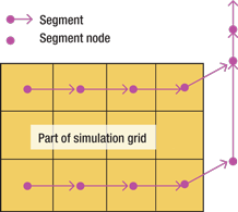
Similar to the traditional nodal analysis that has been used for years to better understand the contribution of each “node” in a production scenario, multisegment well analysis breaks the well into a series of contiguous segments with zero, one or more connections with the reservoir grid blocks, Fig. 1. For each segment, there are four equations (assuming a three-phase black oil simulation): three material balance equations and a pressure drop equation. The latter contains elements that define hydrostatic, acceleration and friction effects. The equations can be solved to yield pressure, flowrate and fluid composition in each segment.
 |
|
Fig. 1. A multisegment well model contains segments consisting of a node and a flow path. Variables are calculated at the node, and intersegment connectivity is indicated by the flow paths.
|
|
A great advantage is achieved over the simple well model case defined earlier. With the multisegment approach, lateral well branches can be analyzed and fluid phase changes can be accounted for, as can complex crossflow conditions between segments. If ICDs are used, they can be represented by discrete segments so their effect on flow can be modeled. In the case of configurable ICDs, the analyst now has the ability to simulate scenarios with ceramic ports of different diameters to evaluate their effect on fluid flow, thereby optimizing the device for the application.
Given the ability to regulate fluid flow through the completion (for either production or injection scenarios), accommodations can be made for variations in reservoir conductivity. Particularly with the long lateral completions used in many wells today, it is exceedingly rare that uniform conductivity will be encountered across the entire completion. High-permeability streaks are common, localized water or gas coning can occur, or near-wellbore formation damage at the heel can affect flow. Any of these conditions can result in non-uniform reservoir drainage, or poor sweep efficiency in the case of an injector.
ICDs work by imposing a pressure drop between the sandface and the tubing to equalize drawdown across the completion. Configurable ICDs offer the added advantage of being able to intelligently control the drawdown at each segment to “fine tune” the performance of each node. Some ICDs can change their response according to the properties of the inflowing fluid. Since ICDs behave as a choke, overall flowrate will be reduced unless bottomhole pressure is reduced, or conversely, unless injection pressure is increased.
MODELING THE ICDs
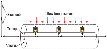
When the multisegment approach is used, each ICD can be designated as a short segment perpendicular to the tubing segments. Using the case of the single wire-wrapped sand screen covering an unperforated tubing section, all production (or injection) must pass through the ICD. Fluid flow is represented schematically in Fig. 2, with flow from the reservoir grid blocks indicated by red arrows and flow between well segments represented by black arrows.
 |
|
Fig. 2. ICDs are included in the multisegment model as individual segments.
|
|
The effect of the ICD can be modeled by additional terms in the equation describing the pressure drop across the ICD. The equation varies for different ICDs, but typically it depends on the fluid properties and the ICD geometry. In the case of the device discussed here, this is where the configurable ceramic flow ports are accounted. Four different ICD designs have been modeled:
• Sub-critical valves—created by making the fluid flow through a restriction. Pressure drop is a function of the fluid density and volumetric flowrate, and the diameter of the restriction.
• Labyrinth device—forces the fluid to negotiate a series of channels. Pressure drop depends on the length and tortuosity of the channels as well as fluid density and velocity.
• Spiral ICD—forces fluid to flow through a spiral.
• Autonomous ICD—similar to the spiral design.
The latter two designs also take into account fluid viscosity. Equipment responses are calibrated in a lab, using known fluids; then, actual fluid properties are imposed and the pressure drop is calculated. The pressure drop depends upon a combination of these fluid parameters as well as the device variables. Accordingly, the pressure drop increases with fluid flowrate, thus acting to retard flow in the fastest flowing zones. This is how coning and sanding conditions are managed.
Other ICD designs can be modeled by deriving pressure drop equations for them. A “universal” solution could involve a table of pressure drops versus flow conditions from which the closest approximation to actual conditions could be chosen to represent the node.
FLEXIBLE APPROACH
The beauty of the multisegment approach is its flexibility. Any number of configurations can be modeled, depending upon the level of detail required. For example, when packers are introduced, lateral sections of the well can be segmented. Either there is a single path into the tubing from each section of the annulus isolated by packers, a “packed annulus” or multiple ICDs between packers, Fig. 3a. Although the multiple path scenario is much more complex, it can be modeled.
If flow within the annulus can be neglected, then there are two modeling approaches, Fig. 3b. In the packed-annulus configuration, each ICD can be modeled individually because each is isolated by packers. However, if more than one ICD is located between packers, they should first be combined into an equivalent ICD segment. A technique called “flow scaling” is used when multiple ICDs are placed between packers.
 |
|
Fig. 3. a) ICDs can control isolated zones in a packed annulus (left), or several ICDs can share a completion zone (right). b) Both scenarios can be modeled. In a packed- annulus configuration, ICDs behave as independent segments (left). When multiple ICDs exist within a completion zone, their contributions are combined (right), but flow in the annulus is ignored.
|
|
Because the ICDs cannot be modeled as individual segments due to their potential interaction, the flow passing through the combined segment is the sum of the flow passing through each ICD lying between the relative packers. The additional pressure drop can be calculated from the equations with a scaled flowrate that allows for the fact that the segment represents more than one ICD. For this to work, the ICDs must be identical, meaning that their ports must be the same. The fluid composition flowing through all ICDs in a segment is also assumed to be identical. Since there is no logical reason for the ports or fluid to be different in this scenario, it is not difficult to model the combined segment; the density, viscosity and ICD constants are assumed to be identical.
Three possible situations exist in determining the flow scale factor. If the length of the combined ICDs between two packers is exactly equal to the distance between the packers, the flow scaling factor is equal to the ICD length divided by the packer interval, Fig. 4a. If the length of the ICDs is less than the length of the distance between the two boundary packers, the flow scaling factor is equal to the length of the ICD divided by the length of all completions, Fig. 4b. If neither is the case, the flow scaling factor may be directly set.
 |
|
Fig. 4. a) When multiple ICDs between packers occupy a length equal to the corresponding tubing segment, the flow scale factor is set equal to the ICD length divided by the length of the tubing segment. b) When multiple ICDs between packers occupy a length less than the corresponding tubing segment, the flow scale factor is equal to the length of the ICD divided by the total length of all completions that feed it.
|
|
FLOW IN THE ANNULUS CONSIDERED
Initially in the modeling development, a simplistic averaging technique was used similar to that illustrated in Fig. 3b (right). This technique ignored flow in the annulus. If multiple reservoir grid blocks feed a single (isolated) ICD, flow in the annulus can be considered, Fig. 5a. For the case where multiple ICDs exist between packers and it is desired to consider flow in the annulus, a “looped flow path” technique has been developed as illustrated in Fig. 5b. This path consists of an entire segment resulting in duplicate identical nodes in some places. The advantage is that all segments thus retain the same basic structure of a node and a single flow path, which allows easy integration into the multisegment well model.
 |
|
Fig. 5. a) Flow in the annulus is considered when multiple reservoir grid blocks serve an isolated ICD. b) Using looped flow paths to model flow in the annulus, when multiple ICDs are present in a zone, more accurately models flow in both the annulus and the tubing.
|
|
A PRACTICAL EXAMPLE
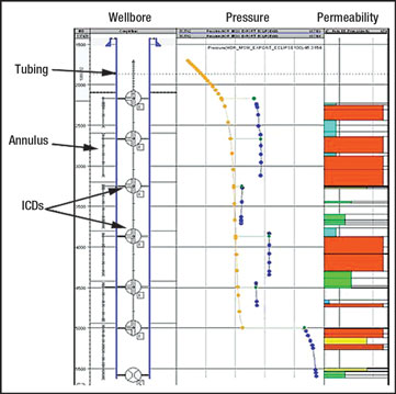
A multiwell reservoir is tapped by several multisegment wells. For the simulation, one well containing six ICDs was chosen. Figure 6 depicts the well and includes a well sketch, records of annulus and tubing pressures and a permeability log. The tubing pressure curve (orange dots) follows a typical shape dictated by friction pressure losses. Gaps in the annulus pressure curves (blue dots) reflect packer locations. The difference between tubing pressure and annulus pressure at any point is the pressure drop across the relative ICD (green dots). In zones with high permeability (red), there is a high pressure drop across the ICD and, consequently, annular pressure is higher. This results in reduced drawdown and flowrates at those places. The opposite is true in lower-permeability areas, as reflected by the low annular pressure. Overall, the flowrate is reduced across the completion, reducing the potential for sanding or coning. Accordingly, the quantity of oil bypassed will be reduced because flow is not dominated by the high-permeability zones.
 |
|
Fig. 6. Simulation results can be seen in this wellbore sketch with relevant logs. ICDs and zone isolation are shown on the left. A zone permeability map is shown on the right.
|
|
Using configurable ICDs, completion engineers can adjust the diameters of the ceramic flow ports to optimize well performance. The procedure works equally well for injector wells. Flow can be adjusted for different zones along the completion for optimized sweep efficiency irrespective of reservoir heterogeneity. The application is believed to be particularly useful in heavy oil areas being produced using steam-assisted gravity drainage (SAGD), where premature steam breakthrough results in high volumes of bypassed oil.
The principles of the modeling technique have been verified using production logs in several North Sea wells following optimized ICD-screen completions. By ensuring that the entire pressure drop is constrained to the ICD under precisely controlled conditions where it can be modeled, flow control devices inside the ICDs can be configured intelligently to achieve desired results. 
ACKNOWLEDGMENT
This article was prepared from IPTC 13925, “Recent advances in modeling well inflow control devices in reservoir simulation,” presented at the International Petroleum Technical Conference held in Doha, Qatar, Dec. 7–9, 2009.
|
THE AUTHORS
|
|
Bryony Youngs is a Modeling and Simulation Engineer for Schlumberger based in Abingdon, UK. She is part of the development team for the Eclipse reservoir simulator suite. She joined Schlumberger in 2008. Before that, Ms. Youngs worked as a post-doctoral researcher at Yale University where she studied geodynamics. She holds an MA in mathematics from the University of Cambridge, UK, an MSc in geophysics from the University of Durham, UK, and a PhD in geophysics from the University of Leeds, UK.
|
|
|
Kieran Neylon is a Principal Software Engineer for Schlumberger based in the Abingdon Technology Center in the UK. He joined Schlumberger in 1998 and has worked on a variety of commercial software applications in the Eclipse simulator suite. Mr. Neylon holds a BEng degree in mechanical engineering from University College, London, and an MSc degree and a PhD in applied mathematics, both from the University of Reading, UK.
|
|
|
Jonathan Holmes is a Scientific Advisor for Schlumberger at Abingdon, UK. His principal area of interest is reservoir simulation, in particular the modeling of wells and surface facilities, multiphase fluid flow and field production/injection strategies. Before entering the petroleum industry, he worked on fluid flow simulation in nuclear reactors for the UK Atomic Energy Authority. Mr. Holmes holds a BA degree in physics and a PhD in astrophysics from Oxford University.
|
|


