SHALE ENERGY: Developing the Bakken—Infill drilling potential and fracture
A fracture modeling and multi-well simulation study evaluates down-spacing potential for horizontal wells in North Dakota.
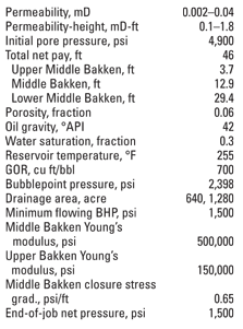
A fracture modeling and multi-well simulation study evaluates down-spacing potential for horizontal wells in North Dakota.Elyezer P. Lolon and Craig L. Cipolla*, StrataGen; Leen Weijers, Pinnacle; Robin E. Hesketh, Oasis Petroleum; and Murray W. Grigg*, Kerogen Drilling activity in the Bakken Formation of the Williston Basin has been booming in 2010, with rig counts up to about 120. Many operators have adopted strategies to drill 5,000-ft or 10,000-ft horizontal laterals on 640-acre or 1,280-acre spacing, respectively. These laterals are hydraulically fractured using multiple fracture treatment stages, either using a plug-and-perf or packer-sleeve completion strategy. Service companies have pushed the possible number of stages that can be conducted up to about 40 per well using a combination of completion strategies. In 2009, Oasis Petroleum was evaluating the feasibility of conducting up to 15 stages in a horizontal lateral, with 10 being the maximum number of stages that could be conducted using a sleeve-packer strategy. This article presents the results of a fracture modeling and multi-well simulation study to evaluate down-spacing potential for Oasis’ horizontal wells in Mountrail County and Burke County, North Dakota. It provides details about fracture treatment designs and subsequent integration of the fracture geometry and conductivity descriptions into the reservoir model. The study also evaluates the effects of changing the number of stages along the lateral, proppant type, treatment volume, fracture conductivity and effective oil permeability. MAPPING AND MODEL CALIBRATION Fracture mapping by downhole microseismic and/or surface tiltmeter technology has been used in the Bakken Formation.1 However, very few results have been publicly disclosed by the operators owning the data, while some of the data that has been released from a single project using a combination of multiple microseismic mapping vantage points (surface, shallow holes and downhole) has been very inconsistent, with no common observed events.2 Results reported from surface tiltmeter fracture mapping in the Bakken showed both longitudinal and transverse fracture growth during a single-fracture treatment to stimulate the entire lateral.3 The transverse fracture system represented between 45% and 60% of all fluid pumped. The distribution of fluid along the lateral was less than desirable, leaving most of the heel of the well unstimulated or understimulated in one treatment. This measurement showed the importance of using more treatment stages placed using improved diversion techniques. Downhole microseismic fracture mapping results generally show significant upward height growth into the Lodgepole limestone. A Bakken-calibrated fracture growth model was used to evaluate the effect of various fracture designs on well performance in the study area. In stimulation designs, slickwater with low concentrations of 100-mesh sand was used during the early stages of the treatment schedule to provide limited conductivity in the narrow fracture network, hundreds of feet away from the wellbore. Subsequently, low-concentration crosslinked gel with 2-ppg, 4-ppg and 6-ppg proppant concentration of either 20/40 mesh Ottawa sand or 20/40 mesh lightweight ceramic proppant was pumped to create more moderate to high conductivity near the wellbore. The treatment size consisted of 100,000–250,000 lb of proppant with injection rates of 30 bbl/min. and treatment volumes ranging from 1,700 bbl to 2,900 bbl. The injection rate must be balanced for two reasons: A high rate is intended to promote diversion/complexity and improve proppant placement far away from the well, while a low rate is intended to minimize upward growth, which is a common problem in the Middle Bakken zone. A core test summary of five wells in the study area is shown in Table 1. Rock mechanical properties listed in Table 2 were obtained from logs and static-vs.-dynamic correlations using core data from nearby wells.
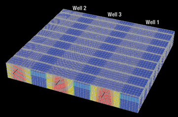
Fracture modeling was performed with the goal of determining fracture dimensions and conductivity using the Bakken-calibrated model and utilizing planned well trajectory and available rock mechanical data. No microseismic fracture mapping was performed as part of this study to verify the modeling results. The 3D lumped-parameter fracture model showed propped half-lengths ranging about 440–660 ft, with average proppant concentration of 0.5 lb/sq ft or equivalent average fracture conductivity of 290 mD-ft. The model indicated a significant out-of-zone fracture growth into the Lodgepole limestone interval (above) and the Three Forks interval (below), with total frac heights ranging 420–630 ft. Similar fracture growth behavior was observed by others in the Bakken Formation.1,4 Although the fracture modeling indicated a downward fracture growth into the Three Forks sand when fracture treatments are initiated from the Middle Bakken, a number of operators have observed that actual production data does not appear to support Three Forks oil production from the Bakken completions. In the study area, not all Bakken fracs communicate with the lower Three Forks interval. Therefore, oil from Bakken treatments is not originating from the combined Bakken-Three Forks system; rather, the Three Forks is separate from the Bakken in production for most wells. It is possible that Three Forks completions also find some Bakken oil in the Middle Bakken, but this has yet to be demonstrated. RESERVOIR MODEL DESCRIPTION A finite-difference, black oil reservoir simulator was used to evaluate the performance of horizontal wells completed with multiple fracture treatment stages. The model consisted of three phases (oil, gas and water) and had three layers in the Middle Bakken interval. At initial conditions, the gas is dissolved in the oil and the formation water is assumed to be immobile. Many Bakken wells produce free-formation water. Depending on the well locations, the free-formation water may contribute significantly to the production. For the study wells, oil is the main production phase with some associated gas production. As the pressure drops below the bubblepoint pressure, the gas is produced with oil at the surface. In the reservoir model, it was assumed that there is no hydrocarbon production from the Lodgepole limestone interval or the Three Forks interval. Three effective oil permeability scenarios were assumed: • A low-permeability case, where the average effective oil permeability was 0.002 mD in the Middle Bakken. The effective (oil) permeability-thickness value for this case is 0.1 mD-ft. • An intermediate-permeability case, where the average effective oil permeability was 0.01 mD in the Middle Bakken. The effective (oil) permeability-thickness value for this case is 0.5 mD-ft. • A high-permeability case, where the average effective oil permeability was 0.04 mD in the Middle Bakken. The effective (oil) permeability-thickness value for this case is 1.8 mD-ft. These assumptions were based on history matching of actual production from six fracture treatments in nearby wells (representing worst and best producers). The vertical-to-horizontal permeability ratio was assumed to be 0.1. The treatment sizes consisting of 100 klb (small case), 150 klb (medium case) and 250 klb (large case) of sand and ceramic proppant were investigated, with the assumptions that fractures grew transversely from the treatment well and that a simple fracture system originated at the center of each stage interval. As such, we have neglected the effects of a distribution of a complex fracture system within each treatment stage, which could impact early-time production behavior. The number of fracture stages was varied from four to 12. Table 2 summarizes the input parameters for the single horizontal well simulation. The target Middle Bakken interval in the study area was drilled at depths of roughly 9,900 ft. Figure 1 shows an example of the fracture grid setup in the reservoir model for the 5,000-ft lateral completed with nine transverse fractures.
EVALUATION OF NUMBER OF STAGES In Fig. 2a, three fracture treatment designs, consisting of 100 klb of 20/40 sand (represented by blue triangles), 250 klb of 20/40 sand (red squares), and 100 klb of 20/40 ceramic proppant (green circles) are compared. Increasing the job size from 100 klb to 250 klb of sand resulted in a production increase of about 25%. For the low-permeability reservoir (kh = 0.1 mD-ft), the optimum number of stages would be greater than the 12 fractures modeled if only one horizontal well was drilled within 640 acres.
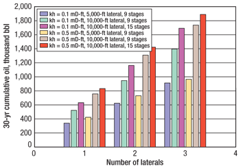
A significant infill drilling potential was noted as a result of the recovery factor of only 3% after five years for the cases shown. Reducing the horizontal well spacing from one well to two or three wells per 640 acres should significantly improve overall recovery. For the high-permeability case (kh = 1.8 mD-ft), 10–12 stages seem to be the optimum number of fractures. Figure 2b compares three other job designs: 100 klb of 20/40 ceramic proppant (blue triangles), 150 klb of 20/40 ceramic proppant (red squares) and 250 klb of 20/40 sand (green circles). The results show that the production resulting from the 150-klb ceramic proppant treatment is higher than the production of the 250-klb 20/40 sand treatment. Ceramic proppant was, therefore, considered beneficial for the higher-permeability case. The relative production gain diminishes when increasing to more than 12 stages for this case. Figure 3 shows 30-year cumulative oil production results for the cases with: 1. low and intermediate effective oil permeability 2. 5,000- and 10,000-ft horizontal laterals with 640-acre and 1,280-acre spacing, respectively 3. use of nine or 15 fracture treatment stages per lateral. The data shows that an increase in the number of stages from nine to 15 results in an oil production increase of about 22% when assuming an effective (oil) permeability-thickness of 0.1 mD-ft. EVALUATION OF DOWNSPACING POTENTIAL The results in Fig. 3 also show that the choice between one 10,000-ft lateral with 15 stages and two 5,000-ft laterals with nine fractures each is almost comparable in terms of cumulative oil production after 30 years. Likewise, two 10,000-ft laterals with nine stages each and three 5,000-ft laterals with nine stages each will yield similar cumulative oil production.
If the number of fracture stages is the same per well, two 5,000-ft laterals will result in more oil production after 30 years than one 10,000-ft lateral, while two 10,000-ft laterals completed with 15 fractures will outperform three 5,000-ft laterals completed with nine fractures. Figure 4a shows cumulative oil production versus time for the 5,000-ft and 10,000-ft laterals if the effective (oil) permeability-thickness is low (0.1 mD-ft). For the scenarios with nine fractures along the lateral, the cumulative oil production increases by about 53% when the lateral length is doubled. Thus, longer laterals will maximize the oil production in the Middle Bakken member. Figure 4b illustrates the impact of the number of fracture stages on oil production. The cumulative oil production increases by about 22% when the number of stages is increased from nine stages to 15 stages.
For the low-permeability-thickness case that was investigated in this study, additional oil production will still be significant when the number of stages is increased to more than 15 (that is, 20 or 30 stages). Now that these larger number of stages per well have become a reality, further evaluation of the impact of a larger number of discrete stages will be necessary. CONCLUSIONS There appears to be significant infill drilling potential as a result of the recovery factor of only 3–7% after five years of production from a single well per 640-acre spacing, with the recovery range varying based on the permeability ranges that were considered. For the low-permeability range considered in this study (kh = 0.1 mD-ft), an increase in the fracture size from 100 klb to 250 klb of sand (1,700- vs. 2,900- bbl slickwater/gel hybrid) is beneficial. It resulted in a fracture half-length increase from about 420 ft to 560 ft, and a production increase of about 25%. In addition, the optimum number of stages is significantly greater than 12, the maximum that was considered in this study. For the high-permeability extreme considered in this study (kh = 1.8 mD-ft), the optimum number of fractures seems to be around 10 to 12 for 640-acre spacing. The relative production increase diminishes when increasing the number of stages to more than 12 for this case. Fracture design and proppant selection, economics, optimum number of stages and infill drilling potential rely heavily on reservoir permeability; therefore, it is critical to directly measure permeability. The easiest method to achieve this is to conduct diagnostic fracture injection tests. *Mr. Cipolla now works for Schlumberger. ACKNOWLEDGMENTS This article was prepared from SPE 124905 presented at the SPE Annual Technical Conference and Exhibition held in New Orleans, Oct. 4–7, 2009. The authors thank Oasis Petroleum, Kerogen Resources, Fidelity, Halliburton and StrataGen for allowing the publication of this work. We also thank Mike Vincent and Mike Mayerhofer for reviewing this article. LITERATURE CITED 1 Besler, M. R., Steele, J. W., Egan, T. and J. Wagner, ”Improving well productivity and profitability in the Bakken–A summary of our experiences drilling, stimulating and operating horizontal wells,” SPE 110679 presented at the SPE Annual Technical Conference and Exhibition, Anaheim, Calif., Nov. 11–14, 2007.
|
||||||||||||||||||||||||||||||||||||||||||||||||||||||||||||
- Shale technology: Bayesian variable pressure decline-curve analysis for shale gas wells (March 2024)
- Prices and governmental policies combine to stymie Canadian upstream growth (February 2024)
- U.S. producing gas wells increase despite low prices (February 2024)
- U.S. drilling: More of the same expected (February 2024)
- U.S. oil and natural gas production hits record highs (February 2024)
- U.S. upstream muddles along, with an eye toward 2024 (September 2023)


