New developments include geochemical logging tools, through- and near-bit sensors, slimhole NMR, and improved mud-logging and gas-extraction technology.
Stephen Prensky, Consultant, Silver Spring, Maryland
With the continued escalation in well costs, especially offshore, and the special requirements presented by the expansion of horizontal development in unconventional reservoirs, the overarching goal in logging and formation evaluation is providing improved cost benefits that increase efficiencies in drilling and well placement, completion design and production. Recent trends include improvements in measurement accuracy and a widening range of tool sizes and deployment options to enable complete reservoir evaluation in smaller boreholes.
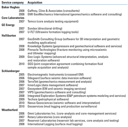
These innovations are increasingly being provided by a few major service companies, due a large number of recent consolidations, Table 1.
| TABLE 1. Recent corporate acquisitions in logging and formation evaluation |
 |
WIRELINE LOGGING
The past year saw many new and enhanced logging tools that have extended wireline technology’s available measurements, accuracy and applicability to tough downhole environments. Additionally, a new paper investigates the errors affecting uncertainty in image-derived relative dip and azimuth in highly deviated and horizontal wells
Static SP tool. The Beijing Energy Development Company designed and developed a prototype electrode tool, the SSPT, to provide more accurate spontaneous-potential (SP) values, better definition of bed boundaries, and improved water resistivity (Rw) calculation, particularly in thin beds. The electrode configuration uses focusing similar to that of a dual laterolog to reduce the borehole (mud resistivity) and shoulder-bed (bed thickness) effects on the SP curve. The tool provides a vertical resolution of about 1 ft. In thick, clean sands, water salinities calculated from the static SP (SSP) curves are very close to laboratory core analyses.1
Geochemical logging. The increased importance of mineral-based lithofacies analysis in complex lithologies, particularly in shale gas exploration and development, has resulted in several new pulsed-neutron “geochemical” or elemental spectroscopy tools, which have been discussed in previous installments of this article. Previous generations of carbon/oxygen-type tools were designed for cased-hole reservoir monitoring; however, the new tools are intended primarily for use in open hole. They are typically run in combination with spectral gamma-ray, density and neutron-porosity tools to acquire maximum data for generating high-resolution interpretations of mineralogy and lithology.
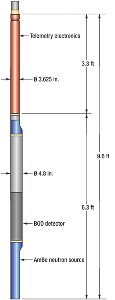
The latest entry is Halliburton’s GEM elemental analysis tool. This device, which uses a standard americium-beryllium (AmBe) chemical neutron source and a bismuth-germanate oxide (BGO) scintillation detector (Fig. 1), provides elemental yields for silicon, calcium, iron, sulfur, potassium, titanium, gadolinium, magnesium and aluminum. The aluminum and magnesium values, which are important for clay and carbonate typing, are also provided by Baker Hughes' FLEX instrument, introduced in 2006 and discussed in the March 2007 installment of this article. (Schlumberger’s original Geochemical Logging Tool, introduced in the late 1980s and since retired, provided an aluminum yield.) The geological model used in the software typically converts the measured elemental yields into weight percentages for the most common rock-forming minerals—i.e., quartz, limestone, dolomite, feldspar, illite, smectite, kaolinite and chlorite. However, the model can be customized to reflect local geology, based on well cuttings or core. Where the data are available, core X-ray diffraction mineralogical analyses are used to calibrate the model.
 |
|
Fig. 1. Halliburton’s pulsed-neutron GEM geochemical logging tool.2
|
|
The new tool is designed to maximize the signal-to-noise ratio of formation-element responses by incorporating borehole gamma-ray and thermal-neutron shielding that reduces detected responses from the borehole and tool. The tool has a depth of investigation of 6 in. and a vertical resolution of 18 in. At the recommended logging speed of 15 ft/min., it acquires four samples per ft. A Dewar flask and a heat sink permit extended operations of the BGO-based spectrometer for extended periods in wells with bottomhole temperatures (BHTs) up to 350°F and pressures to 20,000 psi. The tool can be run in water- and oil-based muds and air-filled boreholes that range 6–20 in. in size. It is combinable with conventional 3⅝-in.-diameter tools.2,3
Accuracy of image-derived dip and azimuth. Uncertainty in image-derived relative dip and azimuth in highly deviated and horizontal wells can significantly impact the determination of reservoir thickness and reserve estimates. To better understand and improve the modeling of this uncertainty, the various factors affecting it—e.g., errors in depth, borehole position, borehole geometry, tool eccentricity, data sampling and resolution—are investigated in a recent paper.4
Wellsite verification of WFT fluid sample integrity. A new wireline formation testing (WFT) sample-chamber design permits noninvasive quality checks of downhole fluid samples (level of contamination) directly at the wellsite.5 The sample chambers are weighed before the job and again at various points in the QC process. The chamber contains a floating piston whose position is measured as the sample is pressurized incrementally in 1,000-psi increments. The pressure at which the piston first moves indicates the internal pressure of the captured sample.
The weight and pressure data are entered in a new software application, which calculates sample density and compressibility, volume and internal pressure. The contamination (integrity) of the sample can be estimated by combining surface measurements with measurements from the downhole fluid-identification sensors (or known density values) to verify fluid type and sample quality. Mud types and expected fluid values are used to determine the estimated fluid contamination level.
Several assumptions must be made to establish the contamination level, and these assumptions (density of filtrate, formation water, formation oil and gas) are selected based on the downhole measurement, or known values. The accuracy of the method is directly affected by the accuracy of these underlying assumptions. This wellsite method is intended to assist in selection of the most representative samples to send to the lab. It can also be useful in situations where high H2S levels prevent opening the sample chambers at the wellsite.
Hostile-environment WFT. Halliburton’s second-generation hostile-environment WFT tool, the Hostile Sequential Formation Tester II (HSFT-II), is capable of operating at up to 450°F and 30,000 psi.6 The tool design addresses many HPHT operational issues encountered with the first-generation tool. Metal-to-metal seals replace O-ring and elastomer seals wherever possible. A variety of pad materials and designs are available to meet specific borehole conditions, and prejob planning is used to determine the appropriate pad type.
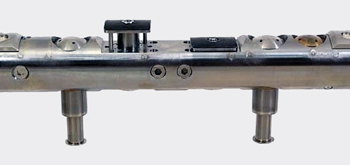
A second independent pad and probe have been added (Fig. 2) to increase pad life and tool reliability at temperatures above 380°F. The two pads can be configured differently to test or sample different zones within the same borehole. In low-mobility (tight) formations, both pads can be deployed to increase the flow area, or a single oval pad (discussed in previous installments of this article) can be used. To meet the higher operational temperature and pressure rating, the tool uses newly designed quartz gauges and a vibrating-tube densitometer for fluid identification.
 |
|
Fig. 2. Halliburton’s HSFT-II shown in single-pad mode. The second, independent pad and probe can be seen in retracted mode.6
|
|
The tool can be run on wireline or conveyed on drill pipe. Metal multifin standoffs replace rubber standoffs, which had experienced premature wear in deviated wells at temperatures exceeding 350°F. The narrow tool diameter—3¼ in. for the body alone and 4¼ in. with fin standoffs—was found to significantly reduce the likelihood of differential sticking, as was the wave shape of the multifin standoffs.
The electronics are flasked to avoid heat-related failure. Also, to minimize the tool temperature during operation and thus extend downhole operation, the new tool uses low-voltage, low-power electronics, highly efficient heat exchangers, and prejob cooling of the electronics. The tool can be powered down completely until required, or operated in a power-saving mode that only maintains communication. A graphic software interface is used to control downhole operation. New techniques are being developed to maximize the limited operational time available to achieve fluid identification and sampling at very high temperatures.
Electromagnetic casing inspection. A new multipad, thru-tubing tool detects internal or external corrosion in up to two strings of tubulars.7 Schlumberger’s 2⅛-in. EM Pipe Scanner uses low- and high-frequency induction currents to make three casing measurements. These measurements are used to calculate surface impedance, magnetic permeability and electrical conductivity, and are combined to quantify metal loss and changes in casing geometry. An imaging section of the tool contains 18 azimuthal sensors deployed on bowsprings (Fig. 3), which are used to generate images of casing thickness (low-frequency) and the surface of the inner wall (high-frequency) for detecting corrosion or defects. Tool measurements are insensitive to nonferrugenous well scale and can detect the inner tool diameter behind such scale.
.jpg) |
|
Fig. 3. The imaging section of Schlumberger’s EM Pipe Scanner, with the azimuthal sensors in bowspring deployment.7
|
|
The tool is rated to 302°F and 15,000 psi and for casing/tubing ODs of 2⅞–13⅜ in., and can image casing of up to 9⅝-in. diameter. It can operate in both liquid- and gas-filled boreholes. A high-speed reconnaissance of the casing is made as the tool is run into the well to flag intervals of interest for the diagnostic scans that are conducted as the tool is pulled uphole. When combined with a multifinger caliper tool in the same run, the tool can provide comprehensive corrosion evaluation for the inner tubing as well as the outer casing in double strings, with full discrimination between internal and external defects.
Multisensor production logging. Hallliburton has added two tools to the line of fullbore production logging tools it initiated in 2002 with the Capacitance Array Tool (CAT)8: the Resistance Array Tool (RAT) and Spinner Array Tool (SAT).9,10 The CAT and SAT were originally developed in collaboration with Sondex. All three tools employ arrays of sensors to provide fullbore fluid-holdup measurements that permit accurate characterization of fluid type, composition, velocity and point-of-entry in segregated- and nonsegregated-flow environments.
In highly deviated and horizontal wells, gravity causes intermixed production fluids to separate and move at different velocities, with lighter fluids moving along the high side of the well. Conventional center-sampling devices cannot accurately quantify fluid distributions and velocities in these wells; this may result in incorrect volume estimates and misdiagnoses of fluid entry or exit points. The problem is exacerbated in horizontal boreholes with undulating well paths.
The CAT has 12 sensors that measure fluid capacitance to distinguish the fluid phases, position in the borehole and determination of fluid holdup in casing and tubing. Each sensor forms part of a circuit that resonates at different frequencies in gas, oil and water. This resonance variation allows the tool to determine what phase (or mixture) exists at a given region across the wellbore. The 12 RAT sensors differentiate between conductive water and nonconductive hydrocarbons by measuring the resistance of very small, fast-moving bubbles. This allows determination of the water holdup cross-sectional profile in all types of boreholes and flow regimes. Both tools include a relative-bearing sensor that makes it possible to determine the position of each sensor in the wellbore and in the flow stream.
The SAT uses six miniturbines (spinners) and an inclination measurement to directly measure phase (or mixture) velocities and direction. Combined use of all three tools allows quantitative estimates of volumetric flowrate for each phase. A new interpretation system displays raw and processed sensor data from the array tools as images to facilitate interpretation. The CAT and RAT are of 1 11⁄16-in. diameter; the SAT tool is of 1⅞-in. diameter. All three are designed for use in casing sizes up to 7-in. diameter. The tools are rated to 350°F and 15,000 psi.
RESERVOIR MONITORING
Recent advances include memory-mode operation pulsed neutron devices and a borehole gravity gradiometer.
Memory-based pulsed-neutron logging. Improved downhole batteries and new power-management technology have allowed conventional wireline thru-tubing pulsed-neutron devices to be adapted for memory-mode operation. In memory-mode logging, battery, electronics and communication sections are added above the pulsed-neutron tool; data are recorded as a function of time (similar to LWD) and stored in downhole memory until retrieval at surface, where they are converted to depth. Battery operation eliminates the need for surface-provided power, therby allowing deployment on slickline and coiled tubing. This, in turn, reduces the need for full-sized rigs and logging units and allows greater operational flexibility. Slickline deployment also increases logging efficiency and operational safety. Together, these factors reduce overall logging costs.
Weatherford’s Memory Pulsed Neutron Decay-Spectrum (MPND-S) tool improves power management by pulsing the neutrons at 200–1,000 Hz in sigma mode, and at 1,400 Hz in elastic mode. Lithium-ion batteries operating in series allow 16 hr of operation. The 128-MB downhole memory stores up to 100 hr of formation data and quality-control parameters. A variety of safety systems have been engineered to prevent inadvertent activation of the tool and to kill tool operation if it hasn’t turned off in response to programed commands. Field tests indicate that the memory data are statistically equivalent to wireline data.11
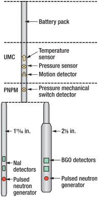
Halliburton’s 1 11⁄16-in. and 2⅛-in. diameter pulsed-neutron tools (called TMD-L and RMT-Elite, respectively) now operate identically on slickline or wireline. In slickline deployment, modules containing the battery, controller clock, memory and downlink electronics are added, Fig. 4. These modules also contain temperature and pressure sensors and motion-detection accelerometers. Memory-mode operation allows up to 10 hr of pulsed-neutron logging. The high-capacity battery allows the neutron generator to operate at full wireline intensity, which enables memory-mode operation to provide identical results to wireline operation. Safety features have been engineered to safeguard against accidental tool activation. The tools are rated to 325°F and 15,000 psi and are combinable with gamma-ray, casing collar locator, and production logging tools in either wireline or memory-mode operation.12
 |
|
Fig. 4. Halliburton’s memory-mode pulsed-neutron logging system.
|
|
Borehole gravity gradiometry. Gravity gradiometry, a measure of differential acceleration of the Earth’s gravity field over a unit distance, is used to measure density changes in the subsurface (i.e., the rate of change of rock properties). A gravity gradiometer can measure up to five of the nine terms that comprise the gravity field tensor. By using first- and second-order differential measurements (i.e., gravity gradients), rather than absolute measurements, many of the environmental factors that affect conventional gravimeters are eliminated. Consequently, this technique can offer a more accurate interpretation of near- and far-field features, including the density of non-horizontal rock formations. Gravity gradiometry is widely used in surface reservoir monitoring.
Gravitec Downhole Instruments Ltd. is developing a borehole ribbon gravity gradiometer.13,14 Sensors based on ribbon gravity gradiometers can be deployed in the borehole as wireline intervention tools or as permanently mounted sensors. A thin metallic ribbon sensor is held at both ends with a knife-edge constraint in the middle, Fig. 5. Inductive readouts mounted along the length of the ribbon can detect very fine deflections in the ribbon produced by the local gravity gradient or changes in the uniform gravity field along the ribbon. The sensor can directly measure the off-diagonal gravity gradient components of the gravity tensor. These measurements are combined with additional input or constraints, using well-established gravity-interpretation algorithms and interpretation methods, to derive a unique solution. Ribbon sensors have the potential for providing azimuthal measurement of density changes that are tens or hundreds of meters away from the borehole. These sensors’ small size allows their use in small-diameter, deviated or horizontal boreholes.
 |
|
Fig. 5. The long, thin design of the ribbon gradiometer sensor is well-suited to borehole applications.14
|
|
Borehole radar for reservoir monitoring. Researchers at Delft University are exploring the concept of a permanently installed borehole radar sensor for near-well imaging (about 30 ft) of fluid movement in production wells.15 In intelligent wells, real-time availability of time-lapse fluid movement data could be used to control fluid flow from different compartments along the wellbore to prevent early water breakthrough or to monitor steamflooding.
LWD/MWD
Last year’s advances include an improved MWD error model, a flexible LWD system for logging through tight curves and slimhole NMR logging.
Wellbore position and survey accuracy. MWD wellbore surveying algorithms use an error model that is based on a mathematical model of the global magnetic field. These algorithms’ accuracy in predicting wellbore position depends on the accuracy of the basic data: the declination, dip angle and total strength of Earth’s magnetic field. However, Earth’s magnetic field is continually changing.
Improvements in geomagnetic modeling, together with more accurate data from magnetic-survey satellites, have been used to update the British Geological Survey Global Geomagnetic Model (BGGM). The use of these revised geomagnetic uncertainty data in the MWD error model published by the Industry Steering Committee on Wellbore Survey Accuracy will reduce wellbore position uncertainty and increase the accuracy of MWD surveys.16
The accuracy of wellbore position surveys decreases in higher latitudes as Earth’s magnetic poles are approached, due to increases in magnetic-azimuth uncertainty. A recent study documented that the uncertainty in lateral position doubles when moving from 60°N to 75°N and suggested a variety of remedial actions to mitigate the problem.17
Test formations. Logging tools must be characterized in formations of known properties before they are deployed in the field. Designing and building test facilities for qualifying new logging tools is a scientifically rigorous process. A number of proprietary and public test facilities (such as the Gas Technology Institute’s test facility in Catoosa, Oklahoma) have been for established for calibrating and verifying single-function logging tools. A recent paper details the design and creation of the test formations used in characterizing Schlumberger’s compact multifunction LWD tool.18
Flexible logging system. The ability to log lateral and horizontal boreholes through the curve section to TD in a single run can result in significant cost savings. Weatherford has developed a flexible 4¾-in. triple-combo LWD system capable of logging through curve sections with dogleg severity to 68°/100 ft in short-radius horizontal wells.19
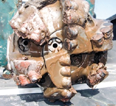
Through-the-bit logging (TBL). ThruBit LLC, the company created to develop and commercialize Shell’s innovative logging-conveyance design (discussed in a previous installment of this article), successfully conducted the first commercial applications in the Deep Bossier trend and Cotton Valley in 2008 and 2009.20 TBL was initially viewed as a safer and surer method for acquiring logs in high-risk wells where sticking pipe and losing wireline tools are serious concerns. Specially designed “portal” bits (Fig. 6), which are adaptable to most PDC bit models and deliver the same performance as standard bit configurations, allow a variety of compact (2⅛-in.) logging tools, including a triple-combo string, to be run through drill pipe and out the bit, or suspended in front of the bit.
 |
|
Fig. 6. The center section of ThruBit’s bit (i.e., the portal) drops down to allow logging tools to pass through.
|
|
TBL is conducted post-drilling and, compared to conventional LWD, offers greater reliability, reduced operational risk, wireline-quality data, and rig time savings (fewer bit trips). The tools are rated to 300°F and 15,000 psi, and can be run in vertical, deviated or horizontal (pumpdown) boreholes. Two operational modes are available: direct-drill mode and security mode. In both modes, the tools can be deployed either on wireline (slickline or E-line) or wireless. In direct-drill mode, the data are acquired in memory as the drillstring is tripped out of the hole. In security mode, which is designed to ensure log acquisition even in difficult borehole conditions, the wireline option allows real-time logging of the borehole below difficult intervals and the drill pipe can be manipulated to avoid differential sticking during logging. In the wireless option (run on a separate wiper trip after TD has been reached), the tool is suspended off the bit after it has reamed past the problem interval, and log data are recorded to memory as the drillstring is pulled out of the hole during a bit trip.
Slimhole LWD NMR tool. Saudi Aramco needed to run nuclear magnetic resonance (NMR) logs in a heavy-oil/tar reservoir to identify viscosity trends so the placement of water injectors could be determined. However, conventional NMR tools, which are designed for boreholes larger than 8½ in., are too large for the slim boreholes (5⅞–6⅛ in.) used in developing the field. The operator collaborated with Baker Hughes to develop a new 4¾-in. slimhole NMR logging tool. Using the latest magnet technology and optimizing the measurement for the smaller hole size resulted in high-quality data. Two prototype tools were delivered within 18 months and are undergoing field tests for a variety of NMR applications, with a commercial version expected soon.21,22
Integrated near-bit pad-contact caliper. Poor borehole quality results in tight borehole, packing off, high torque/drag, stick-slip, degraded log quality, unpredictable directional performance and problematic casing runs. PathFinder’s rotary steerable systems (RSS) use pad extensions just behind the bit to measure offset from the center of the hole. Data from these sensors are used to calculate an accurate mechanical borehole caliper.
By integrating the pad extensions directly into the RSS, the data are always taken at the same position in the BHA without adding complexity or power requirements and without altering the BHA length and behavior, as a separate sub would. Frequency analysis of 2D and 3D images generated from real-time and memory-based caliper measurements (Fig. 7) leads to early detection of borehole problems (e.g., oscillation) while the BHA is still in the borehole. This allows engineers to optimize selection of the drillbit and BHA design for subsequent runs. The pads have an extension range of 1 in., and the caliper is accurate to 0.005 in. (in a calibration ring).23,24
 |
|
Fig. 7. Three-dimensional caliper images and frequency spectrum analysis plots are used to identify borehole oscillation problems, ledges and erratic borehole surfaces. The left side of the caliper images is the borehole’s low side. The height of the plot in the z-axis shows the magnitude of the frequency response.24
|
|
Near-bit resistivity. Baker Hughes has introduced an at-bit resistivity device. At-bit resistivity is an axial, unfocused “toroidal” resistivity measurement in which current from the toroidal transmitter flows down the BHA toward the bit.
Bit resistivity is a raw (uncorrected) qualitative resistivity value. However, when the mud resistivity is known, a mud-corrected resistivity can be computed from the apparent resistivity. At-bit resistivity measurements provide the first look at changes in bed boundaries, which allows real-time selection of core and casing points. Changes in resistivity can also provide early indication of approaching changes in pore pressure (overpressuring) and thereby enable implementation of safety precautions.
The new device is a dedicated sub, available in 6¾-in. and 9½-in. diameters, that is placed directly behind the bit in conventional rotary drilling systems, or behind the steering unit in motor systems and RSS. The bit-resistivity measurement in the new tool has a depth of investigation of a few centimeters and a measure point of about 1 m. At-bit resistivity is available in both oil- and water-based mud.25
Near-bit gamma ray. Halliburton has introduced two near-bit azimuthal gamma-ray devices for drilling systems and geosteering. The At-Bit Gamma (ABG) tool is designed for use with RSS systems and can be mounted directly behind the bit.26 The Gamma/At-Bit Inclination (GABI) sensor, a combination of azimuthal gamma-ray and inclination sensors, is mounted on positive displacement motors and provides continuous real-time gamma-ray images in rotating and sliding drilling modes.27
The ABG sensor comprises three axially mounted sodium-iodide (NaI) scintillation sensors positioned 120° apart that are referenced to the directional package for azimuthal binning used to generate the gamma-ray images. The ABG sensor can be located as close as 3 ft behind the bit box.
The GABI tool can be mounted in any SperryDrill positive displacement motor and is designed primarily for geosteering horizontal boreholes ranging 5⅞–7⅞ in. It comprises two sections, one above the mud-motor power section and one below it. The upper section contains the electronics to support the through-motor short-hop telemetry to the lower section, the communication interface to the LWD/MWD tool, and the data memory. The lower section contains four radially mounted NaI scintillation sensors, positioned 90° apart, a triaxial inclinometer package, and electronics for the short-hop and data acquisition telemetry. The four simultaneous and independent gamma-ray measurements are used to generate four-sector real-time rotary and sliding-mode images and 16-sector memory-data images in rotating mode.
In a typical configuration, the gamma-ray detectors are located 6.5–10 ft behind the bit and the inclinometers another 1 ft uphole. A drive-shaft extension running through the tool’s center transfers torque from the power section to the drillbit. The short-hop telemetry is bidirectional, allowing commands to be passed down and sensor measurements passed up the motor, as required. Data are transmitted to the MWD section located above the motor and transmitted uphole by mud-pulse or electromagnetic telemetry. A lithium battery enables up to 300 hr of continuous operation.
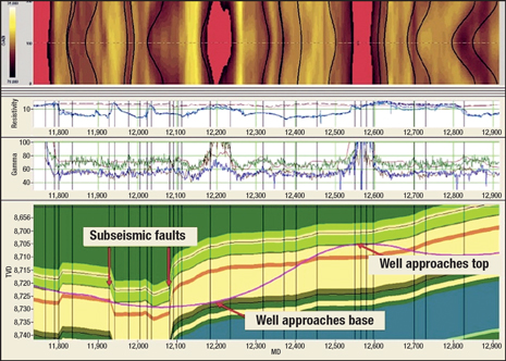
The combination of near-bit inclination and real-time gamma-ray data from near-bit sensors provides the first indications of changing bed boundaries, and image-based dip determination allows evaluation of changes in geologic structure, Fig. 8. These capabilities are valuable for geosteering, optimizing well placement, and in the selection of core and casing points. The gamma-ray images also enable fracture identification. The tool is rated to 300°F and 20,000 psi.
 |
|
Fig. 8. GABI image across small faults and approaching bed boundaries.27
|
|
SURFACE LOGGING
Advances include a high-efficiency wellsite gas extraction system, a portable NMR core scanner, and new mineralogical analysis methods for gas shale applications.
Reservoir pressure from mud-log gas. ConocoPhillips has developed a cost-effective method for obtaining estimates of formation pressure in tight formations where conventional wireline testing is technically or economically unfeasible. They found that in wells with multiple (up to 60) stacked tight sands, WFT was technically ineffective or economically impractical due to the length of time needed to test each zone, the effect of supercharging on the pressure readings, and frequent tool sticking and resulting fishing jobs. The company’s proprietary method, Geobaric Thermal Volume Analysis (GTVA), is based on the observation that the relative pressure difference between drilling and formation fluids has a significant effect on the magnitude of a gas show observed at surface.
This method integrates mud-log gas with drilling and petrophysical data to quantify pressure and gas content. It exploits the gas-reducing effect of increased relative pressure (i.e., increased overbalance) to quantify pressure, quantify formation gas content, and/or predict mud cut in gas-bearing formations. Resolution is sufficient to support zone selection, completion design and identification of bypassed pay, while eliminating the mechanical risk associated with openhole WFT logging.28
Wellsite gas extraction. Baker Hughes introduced Constant Volume Gas Trap (CVGT), a high-efficiency wellsite gas extraction system designed to provide cost-effective acquisition of representative downhole mud-gas data. Improved gas extraction (30–50% over the quantitative gas measurement, or QGM, gas-trap system) is achieved through collision of opposing mud streams from jet nozzles to create very fine mud droplets that release a greater volume of entrapped gas. The system also includes a high-pressure pump and suction strainer assembly with automatic cleaning and flowback that allow it to maintain a constant mud-suction volume despite varying mud-return flowrates.
Designed for use with a fast-cycle gas chromatograph, this system offers more efficient gas extraction, more stable gas detection (reduced influence from environmental factors), and improved gas-ratio analysis. This results in more cost-effective evaluation of reservoir fluids and fluid contacts needed to guide subsequent WFT sampling, completion, testing and production design. Correlating the mud-gas evaluation results with LWD and wireline data leads to improved characterization of reservoir vertical connectivity, compartmentation and caprock efficiency.29
Cuttings lag in high-angle and horizontal wells. Drill cuttings are used for formation identification (lithology) and reservoir characterization (petrophysical properties and hydrocarbon content). Their usefulness in formation evaluation depends on the ability to accurately estimate the well depth at which they originated.
These estimates are based on cuttings-transport models that permit determination of the time (i.e., the lag) required to move the cuttings from drillbit depth to the surface. Lag determination is a function of borehole size, mud properties and flow (circulation), and drill pipe rotation. The models developed for vertical wells allow reliable lag-time determination in these wells. Recent experimental work at the University of Tulsa is part of an effort to develop new cuttings-transport models for use in high-angle and horizontal wells.30
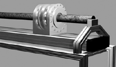
Mobile NMR core scanner. A new portable NMR core scanner developed at the University of Aachen (Germany) provides NMR 1D T2 measurements and 2D T1-T2 correlation experiments of porosity, pore-size distribution and permeability estimates on water-saturated full or split core and core plugs ranging 20–80 mm in diameter.31,32 A tube-shaped Halbach-design magnet-system weighing less than 30 kg is used with a sliding table to allow rapid automatic scanning of long cores up to 60-mm
diameter, Fig. 9.
 |
|
Fig. 9. The portable NMR core scanner uses a sliding Halbach magnet.32
|
|
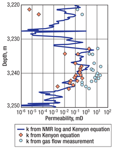
The large sensitive volume of the Halbach magnet and the high signal-to-noise ratio deliver T2 measurement times ranging from a few tenths of a second to a few minutes, depending on porosity, and allow determination of porosity values as low as 2%. Surface or exchangeable cylindrical RF coils are used, depending on the shape and diameter of the core. NMR-derived permeability estimates using the portable scanner compare well with well-log-derived permeability, Fig. 10.
 |
|
Fig. 10. Comparison of NMR well-log (solid line) and mobile NMR sensor data (diamonds). Core-plug gas-flow permeability is also shown (circles).32
|
|
Dielectric rock properties and rock typing. The dielectric properties of sedimentary rocks are used primarily for pore-fluid analysis (i.e., to distinguish freshwater from hydrocarbons) and to provide salinity-independent evaluation of water-saturated rocks. These properties are also sensitive to the rock matrix (i.e., clay content) and can be related to wettability and pore geometry.
Integrating log- or lab-derived data in petrophysical interpretation programs can improve evaluation of thin-bed, carbonate and heavy-oil reservoirs. Concurrent with the recent introduction of new broadband dielectric wireline loggings tools (discussed in a previous installment of this article), new laboratory facilities have been developed to provide dielectric measurements on core and cuttings that can be used calibrate well-logging tools and supplement available petrophysical data.33 A new rock classification model relates lab-derived dielectric properties to lithology. Porosity, cation exchange capacity (CEC) and static relative dielectric permittivity are related to pore geometry, while high-frequency relative dielectric permittivity is a lithologic indicator related to the rock’s electronic density. The statistical model uses discriminant analysis of the two dielectric parameters, CEC, and porosity to identify broad sandstone and carbonate lithofacies.34
Mineralogical analysis in drilling and completion design. The strong interest in gas shales has propelled the formerly obscure field of mineralogical analysis to the foreground. Gas shale reservoirs are typically mineralogically complex rocks composed of varying volumes of quartz, carbonates, clays and organic matter.
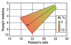
Productive shale reservoirs are very heterogeneous, and rock properties can change rapidly in the vertical and horizontal directions. Identifying the best areas for development (i.e., the sweet spots) requires characterization of the shale formation to determine where it is naturally fractured and/or most easily stimulated through hydraulic fracturing. Fracturing is a function of shale brittleness, which can be defined by geomechanical parameters (i.e., Poisson’s ratio and Young’s modulus), Fig. 11.
 |
|
Fig. 11. A crossplot illustrating the relationship between Young’s modulus, Poisson’s ratio and the brittleness index (BI). Brittleness increases toward the lower left corner of the plot, with increasing values of Young’s modulus and decreasing values of Poisson’s ratio.35
|
|
Brittleness is largely a function of mineralogy, increasing with the volume of hard minerals, such as quartz or carbonates, and decreasing with increasing clay content. Brittleness provides an indication of fracability—i.e., the ease with which rock can be fractured. As brittleness increases, fracture initiation pressure decreases and fracture complexity increases.
Knowledge of the clay minerals present is also critical in the choice of drilling completion fluids to avoid clay-related borehole instability issues and damage to reservoirs containing water-sensitive clays. Characterizing shale mineralogy is essential for optimizing well placement (i.e., geosteering) and designing the completion and fracture treatment to maximize production. Another application is mineralogy-based lithostratigraphy (“chemostratigraphy”), which is used to correlate key stratigraphic horizons for a variety of E&P purposes.36–38
A number of service companies are employing conventional and new technologies, such as X-ray fluorescence, inductively coupled plasma optical emission and mass spectroscopy, and laser-induced breakdown spectrometry, in lab-based automated mineralogy systems (e.g., Intellection/FEI’s Qemscan 39–41) and rigsite-based mineralogical characterization services (e.g., Halliburton’s LaserStrat 42,43). In addition to core- and cuttings-based methods, greater emphasis is also being placed on borehole determination of mineralogy using the latest generation of pulsed-neutron geochemical (i.e., elemental analysis) logging devices.44–48 
LITERATURE CITED
1 Xu, H. et al. “Static SP measurement tool and its field applications,” paper CC presented at the 50th Society of Petrophysicists and Well Log Analysts (SPWLA) Annual Logging Symposium, The Woodlands, Texas, June 21–24, 2009.
2 Galford, J. et al., “A new neutron-induced gamma-ray spectroscopy tool for geochemical logging,” paper X presented at the 50th SPWLA Annual Logging Symposium, The Woodlands, Texas, June 21–24, 2009.
3 Galford, J. et al., “Field test results of a new neutron-induced gamma-ray spectroscopy geochemical logging tool,” SPE 123992 presented at the SPE Annual Technical Conference and Exhibition (ATCE), New Orleans, Oct. 4–7, 2009.
4 Perkins, T. et al., “Wireline and LWD borehole image log dip and azimuth uncertainty,” paper E presented at the 50th SPWLA Annual Logging Symposium, The Woodlands, Texas, June 21–24, 2009.
5 Eyuboglu, S. et al., “New non-invasive sample chamber testing methods confirm downhole sensor measurements and verify sample quality,” paper PP presented at the 50th SPWLA Annual Logging Symposium, , The Woodlands, Texas, June 21–24, 2009.
6 Van Zuilekom, A. and M. Rourke, “Hostile formation testing advances and lessons learned,” SPE 124048 presented at the SPE ATCE, New Orleans, Oct. 4–7, 2009.
7 Schlumberger, EM Pipe Scanner brochure, 09-PR-0064, 2009.
8 Frisch, G. et al., “Integrating wellbore flow images with a conventional production log interpretation method,” SPE 77782, SPE ATCE, San Antonio, Texas, Sept. 29–Oct. 2, 2002.
9 Frisch, G. et al., “Providing accurate PL interpretation with multi-probe, multi-sensor tools in segregated flow environments,” paper U presented at the 50th SPWLA Annual Logging Symposium, The Woodlands, Texas, June 21–24, 2009.
10 Frisch, G. et al., “Improving the process of understanding multiprobe production logging tools from the field to final answer,” SPE 125028 presented at the SPE ATCE, New Orleans, Oct. 4–7, 2009.
11 Campbell, S. et al., “Memory-enabled pulsed-neutron logging tool reduces cased-hole formation evaluation and diagnostics costs,” SPE 121788 presented at the SPE/ICoTA Coiled Tubing and Well Intervention Conference and Exhibition, The Woodlands, Texas, March 31–April 1, 2009.
12 Crawford, D. et al., “Case histories of memory-based pulsed-neutron capture and carbon-oxygen logs on slickline,” paper W presented at the 50th SPWLA Annual Logging Symposium, , The Woodlands, Texas, June 21–24, 2009.
13 Golden, H. et al., “Description of and results from a novel borehole gravity gradiometer,” presented at the Australian Society of Exploration Geophysicists (ASEG) and Petroleum Equipment Suppliers Association (PESA) 19th International Geophysical Conference and Exhibition, Perth, Australia, Nov. 18–22, 2007.
14 Neill, F., “Development of a ribbon gravity gradiometer and its applications for reservoir monitoring,” SPE 124286 presented at the SPE ATCE, New Orleans, Oct. 4–7, 2009.
15 Miorali, M. et al., “A modeling study of a borehole radar system as a permanent down-hole sensor,” paper BG 2.3, SEG International Exposition and Annual Meeting, Houston, Oct. 25–30, 2009.
16 Macmillan, S. et al., “Confidence limits associated with values of the earth’s magnetic field used for directional drilling,” SPE/IADC 119851 presented at the SPE/IADC Drilling Conference and Exhibition, Amsterdam, March 17–19, 2009.
17 Bang, J. et al., “Targeting challenges in northern areas due to degradation of wellbore positioning accuracy,” SPE/IADC 119661 presented at the SPE/IADC Drilling Conference and Exhibition, Amsterdam, March 17–19, 2009.
18 Labous, L., “Customized artificial formation for LWD platform tool development and manufacturing,” IPTC 13956 presented at the International Petroleum Technology Conference, Doha, Qatar, Dec. 7–9, 2009.
19 Azizi, M. I. et al., “Flexible 4¾ inch LWD system enhances short radius horizontal drilling applications in Ghawar Field, Saudi Arabia,” SPE/IADC 125749 presented at the SPE/IADC Middle East Drilling Technology Conference and Exhibition, Manama, Bahrain, Oct. 26–28, 2009.
20 Ernst, S. and C. Matula, “Through-bit tools log difficult wells,” American Oil and Gas Reporter, 52, No. 9, 2009, pp. 115–117.
21 Akkurt, R. et al., “Collaborative development of a slim LWD NMR tool: from concept to field testing,” SPE 126041 presented at the SPE Saudi Arabia Technical Section Symposium and Exhibition, Al-Khobar, Saudi Arabia, May 9–11, 2009.
22 Kruspe, T. et al., “Slimhole application of magnetic resonance while drilling, paper EEEE,” 50th SPWLA Annual Logging Symposium Transactions, 2009.
23 Sugiura, J. and S. Jones, “Integrated approach to rotary-steerable drilling optimization using concurrent real-time measurement of near-bit boehole caliper and near-bit vibration,” SPE 112163 presented at the SPE Intelligent Energy Conference and Exhibition, Amsterdam, Feb. 25–27, 2008.
24 Sugiura, J., “Improving rotary-steerable borehole quality using innovative imaging techniques,” OTC 19991 presented at the Offshore Technology Conference, Houston, May 4–7, 2009.
25 Hartmann, A. et al., “Early bed boundary detection while drilling - testing and application of a bit resistivity device,” IPTC 12063 presented at the International Petroleum Technology Conference, Doha, Qatar, Dec. 7–9, 2009.
26 Kok, K. H. et al., “Case history: A robust point-the-bit rotary steerable system with at-bit imaging and 3D geosteering service integral to optimal wellbore placement in a complex thin sand reservoir,” SPE 121186 presented at the SPE Europec/EAGE Annual Conference and Exhibition, Amsterdam, June 9–11, 2009.
27 Pitcher, J. et al., “A new azimuthal gamma at bit imaging tool for geosteering thin reservoirs,” paper SPE/IADC 118328, SPE/IADC Drilling Conference and Exhibition, Amsterdam, March 17–19, 2009.
28 Lapierre, S. G. et al., “Technology for determining reservoir pressure from mud log gas improves mature, tight gas asset performance: a case study of Ada field, north Louisiana,” SPE 124315 presented at the SPE ATCE, New Orleans, Oct. 4–7, 2009.
29 Zhou, L. and D. Blue, “Reservoir characterization from gas ratio analysis using new high efficiency gas extraction system,” IPTC 13594 presented at the International Petroleum Technology Conference, Doha, Qatar, Dec. 7–9, 2009.
30 Garcia-Hernandez, A. et al., “Determination of cuttings lag in horizontal and deviated wells,” SPE 109630 presented at the SPE ATCE, Anaheim, California, Nov. 11–14, 2007.
31 Anferova, S. et al., “Improved Halbach sensor for NMR scanning of drill cores,” Magnetic Resonance Imaging, 25, No. 4, 2007, pp. 474–480.
32 Pape, H. et al., “Permeability prediction for low porosity rocks by mobile NMR,” Pure and Applied Geophysics, 166, No. 5–7, 2009, pp. 1125–1163.
33 Josh, M. et al., “Practical broadband dielectric measurement of geological samples,” paper DD presented at the 50th SPWLA Annual Logging Symposium, The Woodlands, Texas, June 21–24, 2009.
34 Garrouch, A. A. et al., “A classification model for rock typing using dielectric permittivity and petrophysical data,” Journal of Geophysics and Engineering, 6, 2009, pp. 311–323.
35 Wang, F. P. and J. F. W. Gale, “Screening criteria for shale-gas systems,” Gulf Coast Association of Geological Societies Transactions, 59, 2009, pp. 779–793.
36 Kear, G. R. et al., “Using high resolution lithofacies from spectroscopy logs and microresistivity logs to optimize formation pressure, sampling, and interference testing operations,” SPE 100936 presented at the SPE Russian Oil and Gas Technical Conference and Exhibition, Moscow, Oct. 3–6, 2006.
37 Dix, M., “Using elemental chemostratigraphy for high-resolution correlation and improved geosteering in Mid-Continent gas shales,” presented at the Oklahoma Geological Survey Gas Shale Workshop, October 2008.
38 Sprague, R. A. et al. “Integration of core-based chemostratigraphy and petrography of the Devonian Jauf Sandstones, Uthmaniya area, Ghawar field, eastern Saudi Arabia,” AAPG Search and Discovery Article No. 20065, 2009.
39 Hoal, K. O. et al., “Advanced mineralogy research: Mineral characterization using QEMSCAN techniques,” paper 75-15, Geological Society of America Abstracts with Programs, 39, No. 6, 2007, p. 205.
40 Potter, S.L. et al., “QEMSCAN: A revolutionary sedimentary petrology tool,” paper 42-5, Geological Society of America Abstracts with Programs, 41, No. 7, 2009, p. 142.
41 Sliwinski, J. et al., “A new quantitative method form analysis of drill cuttings and core for geologic, diagenetic, and reservoir evaluation,” CSPG CSEG CWLS Convention, Calgary, Alberta, Canada, May 4–8, 2009.
42 Sumrow, M.H., “Rigsite chemostratigraphy”, Oil and Gas Journal, 99, No. 35, Aug. 27, 2001, pp. 33–40.
43 Halliburton, “LaserStrat wellsite chemostratigraphy service,” service brochure H02801, 2009.
44 Jacobi, D. et al., “Effective geochemical and geomechanical characterization of shale gas reservoirs from the wellbore environment: Caney and the Woodford shale,” SPE 124231 presented at the SPE ATCE, New Orleans, Oct. 4–7, 2009.
45 LeCompte, B. et al., “Evaluation of Haynesville Shale vertical well completions with a mineralogy based approach to reservoir geomechanics,” SPE 124227 presented at the SPE ATCE, New Orleans, Oct. 4–7, 2009.
46 Pemper, R. et al., 2009, The direct measurement of carbon in wells containing oil and natural gas using a pulsed neutron mineralogy tool,” SPE 124234 presented at the SPE ATCE, New Orleans, Oct. 4–7, 2009.
47 Jacobson, L. et al., “Mineralogy analysis from pulsed neutron spectrometry tools,” paper T presented at the 50th SPWLA Annual Logging Symposium, The Woodlands, Texas, June 21–24, 2009.
48 Al-Fawwaz et al., “New era of formation evaluation while drilling of complex reservoirs in Saudi Arabia, paper SPE/IADC 106596 presented at the SPE/IADC Middle East Drilling Technology Conference and Exhibition, Manama, Bahrain, Oct. 26–28, 2009.
|
THE AUTHORS
|
|

|
Stephen Prensky is a consultant to logging service companies, with 37 years’ working experience in petroleum geology and petrophysics. He previously worked for Texaco, the US Geological Survey and the Minerals Management Service. He has served as the SPWLA vice president of technology and as editor of SPWLA’s Petrophysics. He now serves on the SPWLA Technology Committee. In addition to SPWLA, he is a member of AAPG and SPE.
|
|


.jpg)


