Use of industrial methylated spirit was considered critical for flow assurance in an HPHT subsea tieback, but could impact processing and product quality.
Jonathan J. Wylde, Clariant Oil Services
At an HPHT subsea tieback to a gas-condensate platform in the North Sea, gas and fluids from three wells were routed through individual in-field flowlines and gathered at a subsea manifold several miles from the platform. The fluids passed from the manifold through a pipe-in-pipe pipeline back to the platform. Tieback fluids were processed after being commingled with the host platform fluids. Gas and oil were exported via pipelines, and the produced water was reinjected down a disposal well.
Industrial methylated spirit (IMS) was the hydrate control chemical selected for the tieback, and large quantities of it (30 m3) were used to inhibit the pipeline on a “cold start” after depressurization. There was very little data on the phase partitioning of IMS, and quantities could end up at the oil terminal, where they could seriously impact processing and product quality.
To manage the use of such large quantities of IMS, a series of injection trials at the oil terminal were conducted to show how partitioning of IMS occurred. The results proved crucial in risk assessing the impact and use of IMS on the platform. The data has been used to improve the model (cubic-plus-association, or CPA, equation of state and Hysys) data sets. Extensive sampling exercises performed offshore when injecting and processing IMS (necessary to meet export waiver requirements) revealed details of phase partitioning behavior through the platform process plant.
Such considerations are rarely made, nor are such lengths usually taken, to understand the exact partitioning and fate of a chemical when injected offshore. The implications in this instance were significant, and, therefore, the exercise was necessary. The results show that exact quantification is very elusive and that relying on models and standard principles can be misleading and potentially damaging.
INTRODUCTION
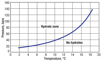
Gas hydrates pose a significant threat to the flow assurance of production systems that contain water and encounter low temperatures and high pressures. Hydrates can plug flowlines during operations with little or no warning. More vulnerable are the transient operations, such as shut-in and startup, where temperatures tend to be lower, pressure differentials (causing gas expansion and, therefore, cooling) tend to be higher, and water can accumulate in low spots. The hydrate curve for the tieback gas is plotted in Fig. 1.
 |
|
Fig. 1. Hydrate curve for the subsea tieback gas.
|
|
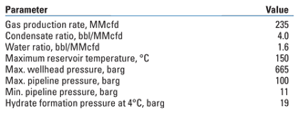
During normal operating conditions, the whole subsea system was outside the hydrate formation envelope, Table 1. Even when shut in, the pipeline had a survival time of over 40 hr before it was necessary to depressurize. During a cold start, however, there was a very high propensity for both ice and hydrate formation due to Joule-Thomson (J-T) cooling across the choke. Further hydrate risks were present when the pipeline was brought up to pressure after the initial J-T effect, as most of the fluids present had been cooled to seabed temperature.
| TABLE 1. Key tieback parameters |
 |
IMS, the hydrate inhibitor selected to protect the tieback fluids, is composed of 99% ethanol (EtOH), 1% methanol (MeOH), with a trace of denatonium benzoate (roughly 50 ppm). The bulk of the IMS used was dictated by pipeline depressurization and specific cold-start procedures. These are infrequent, however, due to the pipeline’s long survival time. IMS was chosen over dry methanol because of the presence of titanium shell and tube coolers in the host platform gas export system. Any dry methanol passing over these coolers could cause catastrophic failure due to stress corrosion cracking.
During a cold start, IMS injection was required subsea for batch dosing of the flowlines before startup, due to initial low temperatures downstream of the choke. Additionally, it was crucial to fully inhibit the pipeline prior to re-pressurization and ramp-up to full production rates.
During a tieback pipeline depressurization, IMS injection would be required topsides to prevent the formation of hydrates in the flare header; this would use 5 m3 of IMS, though to date this operation has not been performed in the field.
COLD-START PROCEDURE
During cold startup, the pipeline pressure was minimal and the temperature was seabed ambient (4°C). When the wells were brought online, the rate at which they were flowed was controlled so that the backpressure in the pipeline did not exceed 19 barg, the hydrate formation pressure at 4°C. However, there are two distinct stages to the cold-start procedure that still presented a significantly increased hydrate formation risk:
Initial startup. The biggest ice and hydrate risks occurred upon initial startup when the choke was opened. The pressure upstream of the choke was over 650 barg; downstream of the choke, the pipeline was depressurized to about 10 barg. Upon opening the choke, the maximum J-T effect could take the absolute temperature down to −60°C. Choke management controlled the effect somewhat, but temperatures had still been observed as low as −40°C. The strategy was to inject 5 m3/hr of IMS at the wellhead to provide a 60% IMS concentration in water (derived from the Hammerschmidt equation) to protect against ice and hydrates. This high-volume injection was required for the first 2 hr of bringing the well online.
Low-pressure flow to compressor. For the next 11 hr, after the initial J-T effect had been overcome, the IMS injection rate was reduced to 1.1 m3/hr. This was not to protect against immediate hydrate formation, as flow was restricted to keep the pressures outside the hydrate formation envelope. The low-volume injection served to ensure that, after the 11 hr, the entire pipeline had been primed with IMS treated fluids so that, when repressurization of the pipeline occurred, the cool gas would be protected as it passed into the hydrate formation zone. Once flow was established, the pipeline warmed up quickly, though an additional 1 m3 could be required to equalize the downhole safety valve if it had closed. About 30 m3 of IMS was required for a two-well cold start.
IMS AND THE OIL TERMINAL
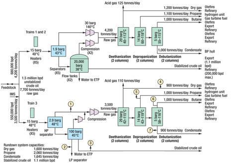
There was great uncertainty regarding the ability of the oil terminal to handle the quantities of IMS expected to enter the main oil line.
Two major concerns existed for the terminal: 1) The strict daily biological oxygen demand (BOD) discharge limitations could be breached if the IMS displayed a high propensity to enter the water phase and get discharged into a local river. 2) The gas process could be affected in a number of adverse ways, including degradation of molecular sieves and effects on butane quality. The ethanol limit was 25 ppm in any single gas product, above which severe fiscal implications existed through either reduced tariffs or flaring requirements.
In a worst-case scenario, it was believed that about 10% of the 25 m3 of IMS injected subsea during a cold start would be exported in the oil pipeline (i.e., 2.5 m3). In this case, it was assumed that this volume of IMS would arrive at the terminal over a period of three hours; thus the IMS rate through each of the three trains would be:
(2.5 m3 / 3 hr) / 3 = 0.28 m3/hr
equivalent to 2,800 L/hr of 10% solution. An injection trial was performed at the terminal, in which aliquots of IMS were injected into the inlet crude. This mimicked the arrival of the tieback cold-start fluids. The trial was designed to fully investigate the gas contamination potential and partitioning of IMS in the oil terminal process system.
BOD was not a primary concern; this could be managed using flow tanks to hold up any ethanol-rich water and slowly bleed it into the produced water to ensure that the BOD limitations were never breached. Furthermore, the IMS contribution to BOD was well understood and quantifiable (1 tonne of IMS is equivalent to 2.1 tonnes of BOD, and the daily discharge limit was 4 tonnes of BOD) without the need for a trial.
IMS INJECTION TRIAL
Hysys modeling of IMS partitioning at the oil terminal was performed, but was a very poor fit with the observed data. The data set on ethanol phase behavior at pressure and temperature was incomplete, and a number of assumptions had to be made using methanol partitioning as an analog. On account of this uncertainty, an IMS injection trial was performed at the terminal.
The trial went through a number of variations before the final operational format was determined. Several different analytical techniques were used in order to get repeatable results. Different injection locations were also used as well as different concentrations of IMS in water. The final selected methodology was injection of a 10% solution in water at the front end of Train 3; when neat IMS was injected, it did not equilibrate with the various phases. The selected analysis for the samples was gas chromatography–mass spectrometry (GC-MS).
It was discovered that significant analytical interference was obtained using GC alone. Molecules were found to elute through the analytical column at the same time as the methanol and ethanol. Further analysis of the molecular ions via mass spectrometry after elution through the GC was able to remove this interference effect. A hydroxycarbonyl anion (m/z 45) was used as a qualifying ion to confirm identity of ethanol, and an ethyl cation (m/z 29) for methanol.
Several trials were necessary to increase the rate of 10% IMS injection so as little risk as possible was posed to the process plant operability. For each trial, air-driven pump units were used to inject the IMS solution. Initially, plant air was used to drive the pumps. However, when the required injection rates became far higher, a temporary diesel-driven air compressor was used, as air consumption rates resulted in low air pressure spikes at the pump inlets.
During the trial, seven streams throughout the plant were sampled and tested for ethanol and methanol content:
1. Raw gas (separator offgas)
2. Effluent water
3. Stabilized crude
4. Dry gas (C1 and C2)
5. Propane (C3)
6. Butane (C4)
7. Condensate (C5+).
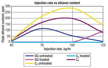
A summary graph (Fig. 2) shows the results for the various product streams (dry gas, C3 and C4). Ethanol was detected in all product streams at varying concentrations, with the highest amount of ethanol passing into the C4 stream, causing this untreated stream to far exceed its LPG export specification of 25 ppm. Both the dry gas and C3 streams were treated: The dry gas passed through molecular sieves and the C3 through amine units, effectively removing ethanol from both gas streams. From Fig. 2, it appears as though the 125-kg/hr trial results were not consistent with the other trials, demonstrating the dynamic nature of IMS partitioning.
 |
|
Fig. 2. Summary of all high-rate IMS injection trials at Train 3 of the oil terminal showing dry gas (DG), C3 and C4 (both treated and untreated) IMS contamination.
|
|
Figure 3 plots the manual and online sample results. It can be seen that there is a delay of about 1.5 hr from the injection of IMS until it is detected in the C4 export stream. Furthermore, the plot shows that the maximum ethanol concentration in the untreated Train 3 propane was 145 ppm, which is less than would have been predicted from the initial trial results (in the 100-kg/hr trial, the concentration was 280 ppm). The treated dry gas (C1 and C2) and the treated propane again show that the processing effectively removes the ethanol prior to export. This is not the case for the butane, and the trial showed that the terminal butane specification was at significant risk even if only small volumes of IMS enter the oil export line at the host platform. A further piece of data shown in the plot is that the manually sampled combined butane data (blue triangles) and the online butane ethanol analyzer data (green line) are very similar, thus validating the online analyzers. The results of these trials quantified the risk both financially and with regard to integrity and allowed appropriate mitigation strategies to be developed.
 |
|
Fig. 3. Manual and online analysis results of the 125-kg/hr trial.
|
|
QUANTIFYING EXPORT IMS
On performing a cold start of the subsea system, hourly sampling was performed offshore to determine the base sediment and water (BS&W) of the export crude. Additionally, hourly sampling of both the export crude and produced water was done in order to perform (onshore) quantification analysis for IMS (ethanol and methanol). Crude oil samples were extracted into water, and the whole contents of the oil containers were extracted to ensure the inclusion of any water in the oil. Produced water samples were analyzed as received or diluted as required. The water extracts/produced water samples were analyzed for ethanol by headspace GC-MS using the same methods as employed during the terminal injection trial.
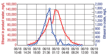
Plotting the volume of IMS exported (a percentage of the total IMS injected at the subsea wellheads) as a function of the export BS&W (averaged from samples taken when IMS is passing through the platform process) revealed a linear trend by which, for a 0.5% BS&W, 5% of the IMS injected would be expected to be exported. This is lower than the original basis-of-design estimates of 10%. Figure 4 shows an example of the detailed ethanol analysis taken from the platform export liquids and produced water after IMS had been used to cold-start the subsea tieback.
 |
|
Fig. 4. Example of the detailed analysis taken after a slug of IMS has been used to cold-start the subsea system.
|
|
From this data it was possible to quantify the volume of ethanol exported, thus enabling the risk to the plant to be understood and mitigation methods quantified before the slug of ethanol arrived at the terminal.
CONCLUSIONS
IMS use created processing challenges at the oil terminal because of ethanol contamination of LPG product streams. Hysys modeling poorly predicted the partitioning of IMS and, therefore, was not able to quantify the risk; this necessitated injection trials at the terminal.
The trials were able to quantify both the financial and integrity risk posed by the use of IMS and allowed appropriate mitigation strategies to be developed. The data generated from sampling the produced fluids offshore after IMS use enabled quantification of the risk prior to the arrival of the IMS, further minimizing the fiscal and integrity-related issues. 
ACKNOWLEDGMENTS
This article was prepared from SPE 133344 presented at the SPE Western Regional Meeting held in Anaheim, California, May 27–29, 2010.
|
THE AUTHORS
|
 |
Jonathan Wylde is the Business Manager for Clariant Oil Services Canada based in Calgary, Alberta. He joined Clariant Oil Services in 2002, initially working in the scale team of the R&D Center in Aberdeen, UK. Over the next four years, he managed the production chemistry on several major North Sea assets. Dr. Wylde earned a BSc degree with honors in geology and a PhD degree at the University of Bristol in the UK.
|
|


