An innovative application of casing-exit technology saved two trips and $2 million in Norway’s Åsgard Smørbukk Sør Field.
Mark Glaser and Tage Heng, Weatherford International Ltd.; and Olle Balstad, Statoil ASA
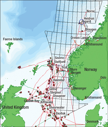
The Åsgard subsea development incorporates three separate fields 120 miles offshore at 984-ft water depth in the Norwegian Sea: Smørbukk, Smørbukk Sør and Midgard, Fig. 1. The prospect development is at an advanced stage with limited availability of subsea template slots for new well development. On Smørbukk Sør Field, there are four templates: three for production and one for injection. The injection template had only one available slot. Since Statoil planned to inject gas into two formations, it was necessary to drill a multilateral well using the single slot. This well would require a Technology Advancement for Multilaterals (TAML) Level 4 multilateral (ML) junction system to prevent sand incursion, which was a problem with both formations, and it would also have to be capable of being switched to production after 10 years of gas injection.
 |
|
Fig. 1. The Åsgard development is located in the extremely harsh region of the Norwegian Sea.
|
|
The project presented complex challenges in a daunting environment. The weather can switch from benign calm to full gale within an hour, and sea conditions can be harsh. The well would be drilled from a semisubmersible rig, and the multilateral system would have to minimize risk in heaving seas, be simple to install, and require as few pipe trips as possible.
There were additional complications: 13% Cr-S-110 casing used for the well would be difficult to mill, and the rock at the casing exit would be hard, impermeable sandstone with possible quartz stringers. The casing exit itself had to be long enough so that a rotary steerable drilling system could navigate through the window to drill the lateral. Finally, the static downhole temperature could reach 284°F.
On the positive side, since injection was to be controlled by a new downhole instrumentation and control system that was undergoing qualification testing, it would not be necessary to maintain full workover access to the main bore after completion of the multilateral. Instead, a hollow whipstock could be left in place and perforated.
The Weatherford/Statoil team decided to take a new approach based on the hollow-whipstock technology used for more than 10 years in the North Sea. The new approach would combine the setting of the whipstock and all milling and rathole operations into a single run, saving two pipe trips and about $2 million in rig costs. Perforating the hollow whipstock through the liner using wireline would save an additional trip, and the resulting perforations would allow fluid access to and from both the main bore and the new lateral. Stage cementing would isolate permeable formations and create a TAML Level 4 junction; liners would include sand screens and swell packers.
The well was successfully completed, and gas injection had an immediate positive effect on adjacent producing wells from both formations. It is unusual to use a multilateral well for gas injection, but this project demonstrated that the single-trip method could be applied to any multilateral well requiring a Level 4 junction.
SINGLE-TRIP TAML LEVEL 4 SYSTEM
The single-trip TAML Level 4 system represents an extension of two existing technologies: hollow whipstocks and single-trip casing exits.
Hollow whipstock. Developed in the 1990s, the hollow whipstock provides a simpler way to construct a TAML Level 4 junction while avoiding the time and risk of installing additional junction equipment. The technology used overlapping casing strings plus cement for maximum strength, stability, and to prevent sand intrusion.1
Hollow whipstocks do not require any special liner or completion equipment and are compatible with reservoir sand control and completion systems, including intelligent well control devices. The disadvantage is that the technology prohibits future re-entry to the main bore below the junction; however, a 2003 review of existing multilateral subsea wells reveals that such re-entry is normally very expensive and often unsatisfactory, making it a low priority.2
The useful feature of the hollow whipstock is that it contains pressure during the milling and lateral drilling stages, and then enables perforating with a zero-phase gun. It is possible to shoot low-debris charges in a single line through the liner and faceplate of the hollow concave without penetrating the backside of the whipstock.
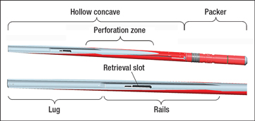
Using the hollow whipstock for both milling and production phases reduces overall risk by eliminating difficult whipstock fishing operations, but mills must be able to pass over the hollow face of the whipstock without damaging or compromising the integrity of the perforation zone. Special whipstock features were developed to achieve this, including a bronze lug at the nose of the whipstock and rails alongside the concave portion. In addition, retrieval features were added in case orientation failed and the tool had to be retrieved before milling began, Fig. 2. The original hollow whipstock required three runs for the running tool, the starter mill and the multilateral window mill.
 |
|
Fig. 2. Hollow whipstock with a 9-ft-long perforation zone.
|
|
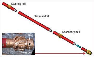
Single-trip casing exit system. The first single-trip casing exit systems were introduced in the early to mid-1990s; it took years of effort to develop a reliable, single-trip casing exit system that incorporated more than one mill. Much of that work went into designing a lead mill with a smooth, smaller-diameter pilot nose with full-gage aggressive cutting blades behind it. The pilot rode on the whipstock’s sacrificial lug and directed the starter mill into the casing wall. New designs for the bottomhole assembly (BHA) included one or two additional mills, depending on the concave angle. These mills helped steer the lead mill to ensure that the exit was milled to gage, Fig. 3.
 |
|
Fig. 3. Milling portion of the single-trip system combines three mills with a shear-bolt mechanism that attaches it to the whipstock.
|
|
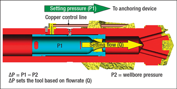
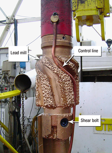
To simplify running single-trip whipstocks, a new setting mechanism for hydraulic anchors was designed. The new design generates hydraulic pressure by flowing drilling fluid through a changeable nozzle restriction inside the lead mill. As a result, increasing the flow creates a greater pressure drop. The high pressure from the upstream side of the restriction flows through a copper line outside the mill to the packer-setting valve below, Figs. 4 and 5.
 |
|
Fig. 4. The whipstock packer is set using the pressure differential created by a restrictive nozzle within the nose of the milling assembly.
|
|
 |
|
Fig. 5. The control line and shear bolt are used to separate the whipstock from the lead mill after the packer is set.
|
|
The system design allowed sufficient drilling fluid flow to operate the MWD without setting the packer. A computer program was used to determine the optimum flowrates. After orientation was set, the flowrate was increased to set the packer and anchor. This system became an industry standard for making casing exits that allowed stiff rotary-steerable systems (RSS) to be run through the window. The only difficulty was that this system was designed for situations where the main bore of the well would be abandoned. For Statoil in the Norwegian Sea, the technology would have to be modified to provide fluid access to both the lateral and the main bore.
Merging technologies. This project provided the opportunity to merge single-trip casing exits and hollow whipstock technology into a single process that would incorporate the best features of both and save substantial rig time.3,4 Several enhancements were incorporated into the system design. First, the rails of the whipstock (the projecting portions on each side of the concave) were extended and strengthened to provide additional support for the pilot nose of the lead mill to protect the integrity of the hollow portion of the concave. Second, the 9⅝-in. packer was redesigned to allow hydraulic setting as described above and was further refined to allow the set packer to withstand 5,000 psi from above and below the packer at 302° F. Third, the two retrieval features of the single-trip system were left in place—a retrieving slot in the side, and a die collar on top—in case the tool had to be retrieved before milling.
RUNNING PROCEDURE
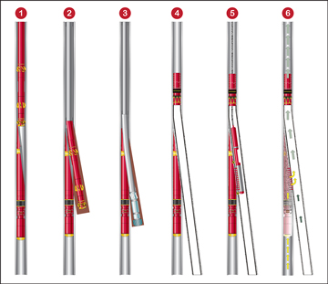
The Weatherford-Statoil team ran the new system using the following basic procedure, Fig. 6:
1. Run the whipstock/packer assembly, orient, set at the required depth, and shear the milling assembly free.
2. Mill the casing exit and rathole, reaming and cleaning it to ensure trouble-free entry of the subsequent drilling assembly.
3. Run the drilling assembly and drill the lateral, logging the positions of the radioactive tags in the whipstock for future reference.
4. Run, set and cement the liner (liner hanger shown at top), perforate the liner and/or perform sand control operations.
5. Run in zero-phase perforating guns to perforate the whipstock. In this case, the team ran the gun on wireline to save time, using the radioactive tags on the whipstock to position and orient the gun.
6. Complete the lateral and start commingled or separate production.
Before start of the running procedure, a gauge run is recommended with a stiff assembly to thoroughly scrape and clean the casing at the point where the whipstock will be set. While some operators may wish to omit this step, it prevents a host of potential problems.
 |
|
Fig. 6. Main steps in creating the TAML Level 4 connection.
|
|
PRE-JOB CONCERNS
While the approach used was straightforward, there were a number of pre-job concerns. First was the issue of milling the super 13%-Cr, 110-ksi) casing. The team reviewed previous milling reports of jobs that had used the same mills for superduplex P-110 with 25% chrome in heavy-wall Q-125 casing to determine the optimum milling parameters for this job. The second concern was that the exit would be in a very competent, dirty and hard sandstone formation. Following a discussion with product line management and R&D engineers, the team decided to have available a diamond mill that had previously achieved very good results as a backup mill in a hard sandstone formation.
Perforating the super 13 Cr casing presented another potential for trouble. Nominal perforation hole size in an 80-kip yield material is 0.33 in. Given the 125-kip yield material, the team anticipated a reduced hole size of 0.32 in. and a corresponding flow area reduction from 2.8 sq in. to 2.7 sq. in. Because of reduced hole size, the team decided to make two perforation runs to ensure sufficient total flow area (TFA) through the hollow concave of the whipstock even if some of the shots missed the perforation area. To deal with high temperature in the well, the team decided to use a high-temperature HMX charge in the perforation guns. This charge can perform after 200 hr at 295°F. Accommodating the substantial heave of the rig required a higher value shear attachment that could withstand the stress and still shear when expected. Finally, the team prepared a detailed procedure to communicate all stages of the completion process, including risk analysis, contingencies, comprehensive pre-testing of assemblies, and every step of the job to provide clear QHSE guidelines and achieve a seamless operation.
MAIN BORE DRILLING AND COMPLETION
Drilling and completion of the main bore proceeded without incident as follows:
1. The 20-in. casing was set at 2,608 ft and cemented to surface.
2. The 13⅜-in. casing was set at 6,936-ft MD and partially cemented with the top of the cement at 5,623 ft.
3. 10¾-in. x 9⅝-in. tapered casing string was set at 13,454-ft MD with a total vertical depth (TVD) of 12,648 ft, and cemented in place with the top of the cement being logged at 7,523-ft MD.
4. The 8½-in. diameter main bore was then drilled horizontally into the lower formation to a TD of 20,538 ft.
After cleaning the main bore thoroughly to TD and running the requisite logs, the team completed it using a 5½-in. sand screen. Because the screen was so long, and because of the critical need to place the top liner hanger at the correct depth, the sand screen was run in two sections.
Run 1: Setting the sand screen lower section. The lower screen section was run to TD. It consisted of a 2,418-ft assembly that incorporated a bullnose assembly; 5½-in.-OD sand-screen sections; 7.9-in.-OD, 5½-in.-ID, 20-lb/ft swell packers at suitable intervals; an upper polished bore receptacle (PBR) for the second section; and a hydraulic release running tool. The assembly was run on 5½-in. drill pipe. Once this assembly reached TD, it was released by circulating a 1½-in. ball to bottom and pressuring up to shear-release the running tool.
Run 2: Setting the sand screen second section. The balance of the main bore screen liner, which was run in next, consisted of a 6.1-in.-OD bullnose with a 2-in. hole; 5½-in.-OD sand-screen sections; the same type of swell packers at suitable intervals; an openhole packer; a hydraulic cementing sliding sleeve (HCSS); a crossover to 7-in., 29-lb/ft tubing; 7-in. tubing; 7-in. liner hanger and packer; and a liner running tool. This assembly was also run on 5½-in. drill pipe. Once this second string tagged the PBR of the lower sand-screen section, the liner hanger was set using the same type of ball-dropping mechanism.
Run 3. Setting the openhole packer and cementing. The new workstring consisted of a shifting tool assembly for setting the openhole packer; a washing tool with HCSS shifting tool; a no-go assembly; 3½-in. wash pipe; 3½-in. drill pipe; and packer-setting assembly, all run on 5½-in. drill pipe. The workstring was run in, landed on the no-go, and then pulled up slowly to snap through the HCSS and openhole packer profiles. A 4-ton overpull indicated that the packer had been set and the HCSS closed. The string was then run back to open the HCSS and position the wash tool for the stage cement.
The stage cement job isolated the permeable formations between the reservoir and the 9⅝-in. casing shoe. Then the team released the drill pipe dart, circulated it to bottom, and landed it with good surface indication. The string was picked up slowly to close the HCSS, and pressure was applied to verify that the HCSS was closed. Then the string was pulled up to clear the packer setting assembly above the PBR to facilitate circulating out the excess cement. After cleanout, the workstring was lowered again to locate the packer-setting dog sub on the top of the liner PBR. A set-down weight of 30 t set the packer, and good surface shear was observed.
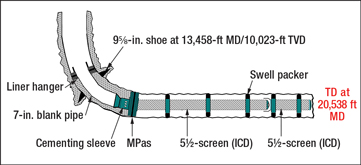
Run 4. Cleaning and logging the hole. The 7-in. and 5½-in. liners and screens, just set all the way to bottom, were cleaned out. The 9⅝-in. casing was then scraped, particularly in the area where the single-trip hollow whipstock would be set.5 These operations were absolutely essential because there would be no future access to the main bore after the lateral was completed, and any debris in the main bore could affect the setting of the whipstock packer. The team also ran an ultrasonic imager-tool log to assess any wear in the 9⅝-in. casing where the single-trip hollow whipstock would be set. This completed work on the main bore, Fig. 7.
 |
|
Fig. 7. Main bore completion.
|
|
DRILLING THE UPPER LATERAL
Even though the new approach to a TAML Level 4 junction eliminated two runs, it still required several runs to complete the job.
Run 5. Milling the casing exit. The mill assembly was attached to the hollow whipstock using a shear bolt of greater than normal strength to compensate for the rig heaving. The whipstock assembly was then run in the well on 5½-in. drill pipe at a controlled rate to minimize stress on the bolt. The whipstock was oriented and the flowrate increased to set the whipstock packer/anchor so that the top of the whipstock would be at 13,607-ft MD and 64° inclination. The whipstock was positioned adjacent to the formation, which was hard, impermeable sandstone with quartz stringers. The team had selected this formation to provide a consolidated formation for milling the window and rathole.
The workstring was slacked off to confirm the setting of the packer/anchor, and then picked up to shear the attachment bolt. The casing pressure was tested to 1,500 psi to verify the integrity of the packer. After completing this successful test, milling of the window was started using minimal weight to avoid digging into the hollow whipstock. Milling of the 9⅝-in. casing-exit window and rathole, each 6 m in length, through the 53.5-lb/ft super 13% Cr casing was completed in a total of 5½ hr. This step was completed by sliding and pulling the mill assembly through the window to ream and polish it. The lack of drag indicated that the window was clean and would provide access for the stiff RSS assembly.
Run 6. Drilling the lateral. In this run, an RSS, consisting of a drilling motor, bent housing, and PDC bit was lowered into the hole and through the window to drill the lateral to 13,586 ft. It took several runs using PDC bits to reach the TD goal of 15,889 ft in the upper formation. Upon reaching TD, pressure points and hole conditions were checked in the sliding mode to ensure that the lateral was clean and up to gage.
Run 7. Running liner and sand screen, and setting packers. The team made up the liner assembly for the lateral and ran it to setting depth at a slow rate (1.5 min. per stand), taking weights up and down, and breaking circulation every 3,219 ft. The string was made up of a bull nose assembly; openhole packer; 5½-in. sand screen; 7.9-in. OD swell packers at intervals; another openhole packer; an HCSS cementing sleeve; 7-in. tubing for the upper liner; liner hanger and packer with PBR; and a liner hanger setting tool, all run on 5½-in. drill pipe.
The liner assembly was run to planned depth, placing the liner hanger and PBR inside the 9⅝-in. casing at 13,179 ft. Then circulation was re-established and the liner hanger was set by dropping a 1½-in. ball, circulating to bottom and pressuring up. After pressure was bled off, weight of 30 t was set down to verify that the hanger was set, and pressure was re-applied to shear out the ball seat and enable the setting tool to be released. A separate run was made to set both openhole packers prior to cementing.
Run 8. Stage cementing. A workstring was made up to open the HCSS, stage-cement the upper liner to isolate the permeable formations above the formation, close the HCSS, clean out excess cement from the 7-in. liner and 9⅝-in. casing, and set the liner-hanger packer. The workstring consisted of a shifting tool for the openhole packer; a wash tool with shifting tool for the HCSS; no-go assembly; 3½-in. wash pipe and drill pipe; and liner-hanger packer-setting assembly. The workstring was run on 5½-in. drill pipe until the packer setting assembly settled in the PBR and landed on the no-go. The workstring was then pulled up slowly to snap the shifting tool through the HCSS and openhole packer profiles and to ensure that the upper openhole packer was set. The cement stand was installed at surface.
After slacking off to the no-go, a stage cement job was performed using the wash tool through the HCSS, thereby isolating permeable formations and the whipstock. A dart was then pumped down to its seat, and additional pressure applied to shear it out to re-establish circulation. Then the string was picked up to close the HCSS, and re-establish circulation to clean out the excess cement in the liner and 9⅝-in. casing. Finally, the liner-hanger packer was set by applying set-down weight on the liner top PBR. To isolate the lateral during perforation and also to facilitate flow through the main bore after perforation was complete, a short 5-in. liner was landed and set inside the lateral’s 7-in. liner.
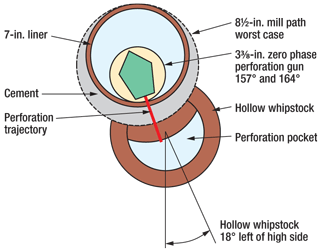
Perforating the hollow whipstock. After the upper lateral was completed, the team flowed the lateral to clean up the lower formation. Then a plug was set in the 5-in. inner liner to isolate the lower portion of the lateral during perforation operations. The hollow whipstock was perforated in two separate runs, one to 13,125-ft MD and the other to 13,333-ft MD. The 3⅜-in. orienting guns were used at two shots per foot with 0° phasing located at 157° and 164° from the high side, Fig. 8. Radioactive tags in the hollow whipstock were used for depth control and orientation.
 |
|
Fig. 8. The hollow whipstock was perforated in two passes.
|
|
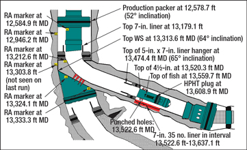
After perforation, the main bore was successfully unloaded and cleaned; however, attempts to retrieve the plug from the 5-in. liner in the lateral were unsuccessful. The only way to gain access to the upper formation was to perforate the 5-in. liner above the plug using limited-entry shots. This operation was successful, and the well was handed over to operations. Figure 9 shows the schematic for the completed junction.
 |
|
Fig. 9. Completed TAML Level 4 junction.
|
|
CONCLUSIONS
The first run of this single-trip hollow whipstock system proceeded without incident. The simplicity of the approach reduced risk for Statoil, and the elimination of two runs saved about $2 million in rig time. The ability to create a TAML Level 4 junction so easily was a major advantage in addition to increasing the stability of the junction and preventing future sand damage.
The well was placed on gas injection at a combined rate of 190 MMcfd with positive response from the producing wells in the same formations. An estimated 30% of the injected gas is going through the perforated hollow whipstock into the lower formation with the remainder flowing to the upper formation. Because this project proceeded so quickly, the downhole control system was not qualified in time to be installed, and the well was completed without it. Because the well was an injection well, it had to be cleaned up using the rig facilities, and platform production facilities could not be used. The ability of the hollow-whipstock approach to isolate the two zones for separate unloading and cleanup was an important advantage. The successful installation of this system in a subsea injection well demonstrates that this technology can be used for many different applications. The caveat is that it requires precise and highly detailed planning of all downhole operations. 
ACKNOWLEDGMENT
The authors would like to acknowledge Aker Solutions for granting permission to publish this article.
LITERATURE CITED
1 Westgard, D., “Multilateral TAML Levels Reviewed, Slightly Modified,” JPT, September, 2002.
2 Redlinger, T. et al., “Multilateral Technology Coupled with an Intelligent Completion System Provides Increased Recovery in a Mature Field at BP Wytch Farm, UK,” SPE/IADC 79887 presented at the 2003 SPE/IADC Drilling Conference in Amsterdam, The Netherlands, 19-21 February, 2003.
3 Glaser, M. et al., “Evolution of Single-Trip TAML Level 4 Multilateral Junction Technology to Reduce Well Costs,” presented at the 2009 IADC World Drilling Conference 17-18, June 2009, Dublin, Ireland.
4 Balstad, O. et al, “New Single-Trip, TAML Level 4, Multilateral Junction Technology Reduces Well Costs in Norwegian Sea Subsea Well - A Case History,” SPE 123935, presented at the 2009 SPE Europe Oil & Gas Conference & Exhibition, Aberdeen, UK, 8–11 September 2009.
5 Horne, K. et al., “The Evolution of a TAML L-4 Multilateral System to Meet the Challenges of a BP Deepwater Subsea Well,” presented at the 2007 SPE/IADC Drilling Conference in Amsterdam, The Netherlands, 20-22 February, 2007.
|
THE AUTHORS
|
| |
Olle Barstad is the Principal Engineer for well technology operations at Statoil ASA.Mr. Barstad graduated from the Norwegian Institute of Science in 1998 and holds a MS degree in Petroleum Engineering. He started his career as a roughneck for Odjell Drilling in the North Sea, and joined Statoil ASA in 2003, planning completions and interventions for the Åsgard license and working both onshore and offshore.
|
|
| |
Mark Glaser is the Engineering Manager for re-entry systems for Weatherford International Ltd. He has 34 years of experience working with multilateral, drilling, fishing, milling, completion and cementation products. He earned a degree in mechanical engineering and an MBA from the University of Houston.
|
|
| |
Tage Heng is Sales and Operation Engineer for Weatherford International’s Fishing and Re-entry group in Stavanger, Norway. He joined Weatherford in 2000 after 10 years of industry experience.
|
|


