SPECIAL FOCUS: DRILLING REPORT
Drilling induced vibration may cause riser fatigue
Modifying drilling practices can avoid damage related to close annular tolerances.
Roger T. Chang, Engineering, Research & Computing
Drilling Induced Vibration (DIV) is a relatively new field observed phenomenon. It is most likely to occur in narrow annulus drilling such as casing drilling or re-completion through a top-tensioned production riser. Most research was done by testing. An analytical procedure using a Multi-Tube riser modeling scheme was developed to assess quantitatively the DIV amplitude, bending moment and associated fatigue damage. The results coincide with field observations and tests. Field operations to avoid DIV are suggested.
No published literature addressing the DIV issue was found. Most research was done by experiment and those test results are confidential and proprietary. The general consensus from researchers in the field is that:
1. DIV seems to occur only in tight-annulus risers, e.g., casing drilling or workover in the production riser.
2. DIV seems to occur only during drilling in hard formations, i.e., at very slow penetration rates.
3. Changing drill pipe rotating speed seems to alleviate, if not eliminate, the vibration.
4. Changing circulating fluid density also seems to alleviate the vibration.
There are logical explanations for these observations. Any vibration must have its cause. For DIV, it is the contact between the drill pipe and outer riser, Fig. 1. The narrower the annulus is, the higher the possibility of contact occurring. When drilling a hard formation, the contact load becomes a periodic loading on the outer riser. If the drill pipe rotating speed matches the outer riser’s natural frequency, resonance happens and vibration is observed.
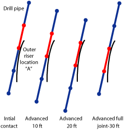 |
Fig. 1. The driver for drill pipe induced vibration is the contact load between the drill pipe’s tool joint and the outer riser.
|
|
Changing the drill pipe rotating speed eliminates one part of the necessary resonance condition. Changing fluid density will alter the riser’s natural frequency, hence, eliminating the other part of the necessary resonance condition.
ANALYSIS METHODOLOGY
Since DIV is a new “buzz word,” there is no well-developed or well-accepted analytical procedure to quantitatively calculate its vibration magnitude and induced damage. But, the above logical explanations led to developing these procedures:
Step 1. Perform centralizer analysis to obtain the contact loads at the drill pipe tool joints.
Step 2. Perform Eigenvalue analysis to obtain the riser system’s natural frequencies. The added mass must be included in the natural frequency analysis, since the riser is in water.
Step 3. Perform steady-state dynamic analysis to obtain the deflections and bending moments along the riser. The contact loads obtained in the centralizer analysis should be used as the periodic loading. Theoretically, these loading periods should be exactly the same as the natural frequencies obtained in Step 2. However, it is known that resonance occurs within a bandwidth (not necessarily exact), therefore, the contact load periods may be varied in the rotating speed study.
Step 4. From bending moment, the stress amplitude may be calculated by the section modulus (Z = I/c).
Step 5. With fatigue curve and Stress Concentration Factor (SCF) data, the allowable number of cycles (N) may be calculated by  , where A is a constant. With the estimated number of occurrence (n), the fatigue damage (D) may then be calculated by D = n/N. , where A is a constant. With the estimated number of occurrence (n), the fatigue damage (D) may then be calculated by D = n/N.
Except for the first step, the steps above are quite typical and straight-forward procedures for determining fatigue damage caused by dynamic vibration. Hence, centralizer analysis is further explained.
CENTRALIZER ANALYSIS
Traditionally, riser analysis is performed using a composite modeling scheme, in which only one mathematical line of elements represents the masses, weights, areas and inertial moments of all riser strings. In doing so, the load distribution among riser strings is completely missed, not to mention the contact loads between the riser strings.
The Multi-Tube riser modeling scheme1 on the other hand, models each riser string as a separate line of elements. It fully captures the load path and has advantages over the composite model in performing riser installation/completion sequence simulation analysis2 and riser centralizer analysis.3
In the model, there are two ways to confine the inner riser string inside the outer riser string. The first is by using Kinematic Constraint (KC); the second is by Gap Element (GAP). Centralizer analysis, for sizing centralizers and their locations, uses GAP to determine the contact loads between the centralizers and outer riser.
Since the DIV driver is the contact load between the drill pipe coupling (tool joint) and the outer riser, the coupling is treated like a centralizer in applying the Multi-Tube centralizer analysis methodology. Also, because the drill pipe is constantly advancing, a parametric study of the coupling locations has to be performed. For a typical 30-ft drill pipe, three drill pipe advancements were studied.
HESS PRODUCTION RISER
Hess Corp.’s Equatorial Guinea Northern Block G development has two tension leg platforms, Oveng and Okume. For horizontal well drilling, the company decided to drill through production riser instead of using a drilling riser. There were concerns about the potential fatigue damage that might be caused by this drill-through operation.
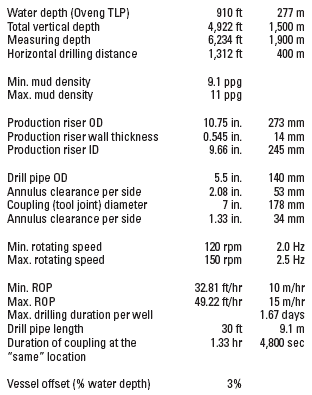
Table 1 summarizes the drill-through operation for Oveng TLP. The first data block is of water depth, total vertical depth, measuring depth and horizontal drilling distance. The horizontal drilling distance is most important for the Hess project because of its objective.
| TABLE 1. Hess production riser drill-through paramaters |
 |
|
The mud density range is listed in the second block, whereas the third data block is of the production (outer) riser. Drill pipe (inner riser) OD and tool joint diameter are listed in the fourth block along with their annulus clearances per side with respect to production riser ID. The drill pipe rotating speed range is listed in the fifth block, an increment of 0.1 Hz between the upper and lower bounds will be analyzed for dynamic response.
The minimum and maximum rates of penetration (ROP) are listed in the sixth block. The maximum duration of drilling per well is the horizontal distance divided by the min ROP. Since the drill pipe is advancing, a ‘fixed’ location on outer riser location (point A in Fig. 1) will only be subjected to the same contact load every drill pipe length of times, so the duration of coupling at the same location is further divided by the drill pipe length. Note this is a hypothesis for determining the number of occurrences (n) in fatigue damage assessment.
STEP 1: CONTACT LOAD DETERMINATION
The Multi-Tube model with GAP as the interface between the outer riser and drill pipe was used to determine the contact loads for three drill pipe advancements, Fig. 2. Note the results are for a vessel offset of 3% water depth.
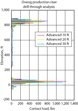 |
Fig. 2. This analysis shows that contact loads occur only at the tool joints near the keel joint (top) at about 850 ft and near the stress joint (bottom) at about 60 ft.
|
|
Because the stress joint and keel joint are two most-bent regions, higher contact loads are expected. The riser joints between them are almost on a straight line due to the applied top-tension; hardly any contact is observed. Contact only occurs at tool joints near the keel joint (top) at about 850 ft and near the stress joint (bottom) at about 60 ft.
STEP 2: NATURAL FREQUENCY ANALYSIS
Natural frequency analysis was then performed for all three drill pipe advancements; up to 50 modes were extracted. The graph in Fig. 3 shows natural frequencies over the rotating speed range of interest.
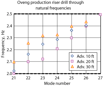 |
Fig. 3. Drill pipe’s natural frequencies vary significantly over the normal rotational speed range.
|
|
The drill pipe’s natural frequencies are the same at the lower modes (1 to 6). A slight difference among three drill pipe advancements is seen at the higher modes because the outer riser and drill pipe can have different mode shapes in the higher modes, depending on the contact element status (open or close). Also, there are seven modes (21 to 27) in the frequency range of interest.
STEP 3: STEADY-STATE DYNAMIC ANALYSIS
Assuming that the contact loads obtained in Step 1 are periodic loading acting on the outer riser (the period being the drill pipe rotating speed), steady-state dynamic analyses in the frequency domain were performed. Six rotating speeds were studied; 2.0-2.5 Hz in 0.1 Hz increments.
Figure 4 is the deflection plot for the 10-ft pipe advancement showing the full riser length. Observe that the production riser excites in different modes depending on the assumed periods (0.5 to 0.4 sec) of the contact loads.
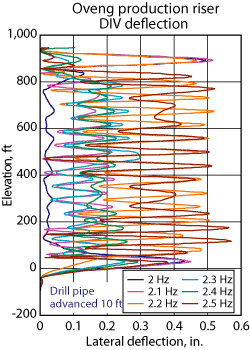 |
Fig. 4. The production riser excites and deflects in different modes, depending on the contact load periods.
|
|
Figure 5 is the moment plot for the 10-ft pipe advancement. Due to the inclusion of soil in the riser model, the highest moment is at about 25 ft below the mud line. The moment value of 8.79 ft-kips at the stress joint top of 2.5 Hz curve is identified for the bending stress calculation in the next figure.
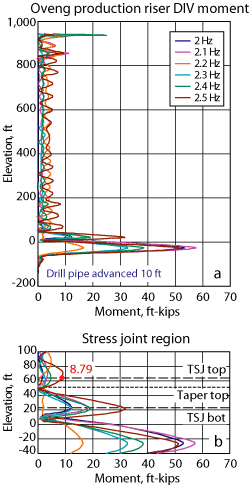 |
Fig. 5. For a 10-ft pipe advancement, the highest moment is at about 25 ft below the mud line.
|
|
STEP 4: ALTERNATING STRESS CALCULATION
Figure 6 shows the bending stress amplitude plots for the same case. It should be noted that proper dimensions (OD, ID and section modulus Z) were assigned to each element to calculate bending stress, except for the structural components below the stress joint and above the tension joint, since they are not part of riser system deliverables. At the stress joint top, the section modulus is 40.19 in3 with 5% wall thickness reduction. Therefore, the bending stress is 2.625 ksi (8.79*12/40.19, where 12 converts ft to in.).
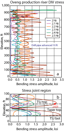 |
Fig. 6. The bending stress amplitude plots show significant stress changes depending on rotational speed.
|
|
STEP 5: FATIGUE DAMAGE CALCULATION
Fig. 7 shows the fatigue damage plots for the same case. SCF of 1.6 was assigned to each connector along the Oveng production riser. DNV Clause B curve has an A of 4.51e11 ( in ksi) and slope (m) of 4. So, for bending stress amplitude of 2.625 ksi, the allowable number of cycles N is calculated as 4.51e11 * (1.6*2*2.625)-4 = 9.05e7, where 1.6 is SCF and 2 converts stress amplitude to stress range. in ksi) and slope (m) of 4. So, for bending stress amplitude of 2.625 ksi, the allowable number of cycles N is calculated as 4.51e11 * (1.6*2*2.625)-4 = 9.05e7, where 1.6 is SCF and 2 converts stress amplitude to stress range.
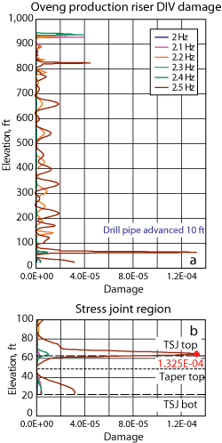 |
Fig. 7. The fatigue damage plots demonstrate the SCF effect on fatigue damage, with the greatest damage at the first conductor above the stress joint.
|
|
The number of occurrences was calculated as 4,800*2.5 =12,000, where 4,800 is the duration of coupling at the same location and 2.5 Hz is the maximum rotation speed, both from Table 1. Note that for other curves Hz will be different. The damage at the stress joint top of 2.5 Hz rotating speed is 1.325e-4 (12,000/9.05e7) as shown in the stress joint graph.
The same five steps calculating the fatigue damages for the 20-ft and 30-ft drill pipe advancements were also performed, but are not presented.
FATIGUE LIFE CALCULATION
The maximum damage for all six rotating speeds and three drill pipe advancements were searched along the full riser length, and their reciprocals were designated as the DIV fatigue life for the combination case of rotating speed and drill pipe advancement. Note, even though it is called fatigue life, it does not have the same meaning as the typical fatigue life because DIV damage does not happen annually.
Figure 8 is a graphical presentation of DIV fatigue life. The X-axis is the fatigue life presented in logarithmic scale and reversed order, so that the least life is on the right of graph. The Y-axis is the drill pipe advancement (ft). It should be noted that the fatigue lives at zero advancement are the same as those at 30-ft advancement. Also, two fatigue lives are identified in the graph: 7,545 yr of 10-ft drill pipe advancement and rotating speed of 2.5 Hz is the reciprocal of 1.325e-4 in Fig. 7 and the least fatigue life of 30 yr occurs at 20-ft drill pipe advancement and 2 Hz rotating speed.
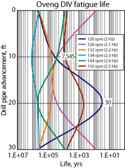 |
Fig. 8. DIV fatigue life can vary widely depending on the speed of drill pipe advance and rotation, in this case from 7,545 yr to 30 yr.
|
|
This graph demonstrates drastic fatigue life differences at different rotating speeds. It also illustrates that fatigue life varies as the drill pipe advances a full joint length, an interesting yet important finding.
CONCLUSIONS
Based on the analysis results, DIV-caused damage is very sensitive not only to the drill pipe rotating speed, but also to the tool joint location (drill pipe advancement). The first part of this conclusion coincides with field observations. The second part suggests that DIV should not be a concern, if the drill pipe keeps advancing. This also suggests that constant rotation speed should be avoided at all costs when drilling encounters a hard formation (i.e., ROP is near zero). 
ACKNOWLEDGEMENTS
The author thanks Hess Corp. for their permission to publish this Drilling Induced Vibration work performed for its Equatorial Guinea Northern Block G development.
LITERATURE CITED
1 Chang, R, E. Fisher, H. Underland and M. Wu, “Riser modeling scheme: Multi-Tube vs. Composite,” paper 8012 presented at the ASME OMAE Annual Conference in New Orleans, La., 2000.
2 Chang, R, and Smedley, M., “Multi-Tube model application in riser installation/completion simulation analysis,” paper 37416 presented at the ASME OMAE Annual Conference in Cancun, Mexico, 2003.
3 Chang, R, and Yu, J, “Multi-Tube model application in riser centralizer analysis,” paper 37417 presented at the ASME OMAE Annual Conference in Cancun, Mexico, 2003.
|
THE AUTHOR
|
|
Roger Chang is president of Engineering, Research & Computing of Houston, Texas. He earned a BSCE degree from National Cheng-Kung University in Taiwan and an MS in hydraulics and mechanics from the University of Iowa. Prior to starting Engineering, Research & Computing in 1990, he was director of Analytical Systems at Cameron Offshore Engineering. His specialty is riser analysis and he has been responsible for the riser analysis program for seven major offshore developments. Chang’s main contribution to the oil industry is the Multi-Tube modeling scheme.
|
|


