When flow assurance fails: Melting hydrate plugs in dry-tree wells
Transient simulations assisted hydrate remediation efforts in deepwater Gulf of Mexico wells.
DEEPWATER TECHNOLOGYWhen flow assurance fails: Melting hydrate plugs in dry-tree wells
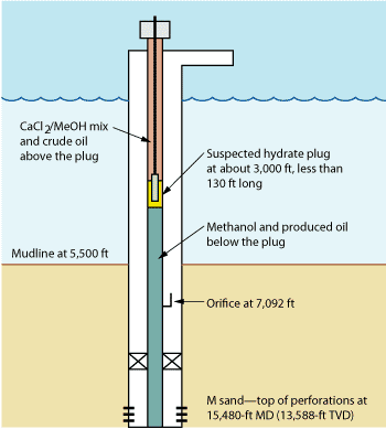
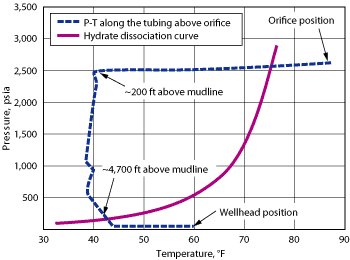
Transient simulations assisted hydrate remediation efforts in deepwater Gulf of Mexico wells.Amrin F. Harun, Thomas E. Krawietz and Muge Erdogmus, BP America. In deepwater oil wells, thermodynamic conditions are favorable for the formation of gas hydrates, which tend to agglomerate and plug wells, reducing flow and sometimes causing damage to infrastructure. Because hydrates are very difficult and expensive to remediate, offshore operators spend significant resources to avoid operating conditions that might allow hydrate formation, including the injection of chemical inhibitors into the wellbore. However, these flow assurance methods are not always successful, leaving operators the difficult task of dissociating the hydrate plugs to restore production. To determine the temperature and pressure conditions under which hydrates can form, the best approach is to conduct experimental measurements on the appropriate hydrocarbon/water mixture. However, this is not always practical, so it is more common to use thermodynamic models to predict hydrate behavior by calculating the hydrate equilibrium curve, also known as the hydrate dissociation curve. This is a prediction of temperature, at a given pressure, above which hydrates will not form. Hydrate plugs formed above the mudline in three dry-tree oil wells in the Gulf of Mexico. After several unsuccessful attempts to remove the hydrate blockage, injection of hot oil into the tubing-casing annulus was considered. Transient simulations were performed to determine the required injection temperature, rate and time. The hot oil injection successfully melted all three plugs, and practices were implemented to prevent future hydrate problems both in the slickline operation and in startups. INTRODUCTION A slickline operation was being performed in a dry-tree well in the Gulf of Mexico when the tool string became stuck at a water depth of about 3,000 ft while pulling out of the hole. A hydrate plug was suspected to have formed inside the production riser above the mudline. This was supported by the loss of movement of the spang jars. Estimated hydrostatic pressure and temperature inside the wellbore after shut-in were compared with the hydrate dissociation curve and shown to be favorable for hydrate formation. On two other dry-tree wells that had been shut in at the wellhead and at the Surface-Controlled Subsurface Safety Valve (SCSSV) due to hurricane evacuation, hydrate plugs were suspected to have formed when the SCSSV was opened to bring the wells back on production. Even though an Anti-Agglomerate Low-Dosage Hydrate Inhibitor (AA LDHI) was injected into the wells before shut-in, a hydrate plug was believed to have formed inside the production riser above the mudline. Further analysis showed that an inadequate amount of LDHI was injected due to calibration problems with the injection skid. Hydrate formation was supported by the pressure buildup in the tubing when crude oil was injected to confirm that the SCSSV had opened. Estimated hydrostatic pressure and temperature inside the wellbore after shut-in were compared with the hydrate dissociation curve and shown to be favorable for hydrate formation. Several unsuccessful attempts were made to melt the hydrate blockage. These included pumping methanol through the chemical injection line below the plug and pumping glycol down the tubing above the plug. Before trying to remove the plug with coiled tubing, injection of hot oil into the tubing-casing annulus was attempted. Thermal-hydraulic transient analyses were performed to determine injection temperature, pumping rate and pumping time at which hot oil would need to be injected through the 4½ x 9⅝-in. annulus. The transient simulation results confirmed that the existing topside facilities were adequate to support the operation. Well integrity issues mainly involved the compatibility of hot oil with elastomers and possible asphaltene or paraffin precipitation in the wellbore annulus. HYDRATE ISSUES IN A DRY-TREE WELL In a dry-tree well, the most critical area that is subject to hydrate formation, particularly during extended shut-in and cold startup, is along the wellbore above the mudline, since there the production riser is in direct contact with the sea ambient. During an extended shut-in, phase segregation in the wellbore causes a gas cap to form, and, depending on the gas-oil ratio and pressure, the gas cap may extend down to the mudline. If water is introduced into this cold gas column either due to condensation or other stimuli and agitated, then hydrates may form and grow into a blockage. Therefore, the best practice for extended shut-in is to push the wellbore fluid below the mudline using a dry gas mixed with methanol, dry crude or diesel. Another preventive measure during a planned shutdown is to inhibit the well by injecting an AA LDHI through the downhole injection mandrel for some time before shutting in the well. Remedial action for a dry-tree well is to reduce pressure, increase temperature, inject chemical or change fluid composition. This is to remove the hydrate and/or move wellbore fluids out of the thermodynamic region that encourages hydrate development. The action can fall into any of the following five categories: Pressurization. A pressure higher than the BHP is applied to move the plug, typically downward. This is rarely effective, since increased pressure tends to solidify the plug by moving thermodynamic conditions further into the hydrate-forming region. Depressurization. Reducing pressure in the riser causes a temperature decrease at the hydrate interface, resulting in heat exchange when the external temperature becomes greater than the hydrate equilibrium temperature. The tubing pressure must be bled off in a controlled manner, because a sudden and great pressure differential during dissociation may turn the hydrate plug into a projectile, launching it up the tubing where it could damage downstream equipment. Chemical injection. A thermodynamic inhibitor, usually methanol or glycol, is pumped down the tubing through the chemical injection line or the access port. Applied heat. Often in pipelines and flowlines, heat is applied to the plug from outside the line, either by mechanical means-such as in an electric heated flowline, where heat is applied to specific points using electric coils wrapped around the flowline-or by circulation of heated fluids outside the line, as in heat-medium pipelines. This practice is applied when the plug location is known and dissociation can be controlled. In these cases it is recommended to apply heat to the hydrate location from upstream. Heat applied to the line at the center of the hydrate location could cause over-pressurization, dislodging the plug and launching it upstream. Mechanical removal. Coiled tubing is used to drill, circulate heated fluids or run a heated wireline broach. It is usually successful in reaching and eliminating the plug, and it is applicable when equipment is readily available and cost-effective. However, use of these tools in the hydrate-formation region may cause the tools to become stuck if hydrates re-form. Also, drilling operations may encounter significant pressure differentials as the hydrate breaks up, releasing gas trapped inside it. OPERATIONS AND WELLBORE CONDITIONS Well A-5 is a gas-lifted oil well with an orifice, or gas-lift valve, located inside the gas-lift pocket mandrel at 7,092 ft below the sea surface, Fig. 1. The mudline is located at 5,500 ft of water depth. A slickline operation was being performed when the tool string suddenly became stuck, suggesting a hydrate plug. The estimated hydrostatic pressure and temperature inside the wellbore after shut-in were plotted against the hydrate dissociation curve, revealing that conditions were favorable for hydrate formation in the range of about 100-4,700 ft above the mudline, Fig. 2. Based on the location at which the tool string was stuck in the wellbore, the expected location of the hydrate plug was 3,000 ft below sea level and its expected length was 130 ft.
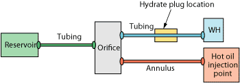
An attempt to melt the plug from the top by pumping down the tubing 63 bbl of crude at 100°F and 9 bbl of calcium chloride/methanol mixture was unsuccessful. Another attempt was made to melt the plug by injecting methanol through the downhole chemical injection valve at 5,879 ft (below the plug), but without success. Well A-9 is a dry-tree, gas-lifted oil well with an orifice located inside the gas-lift pocket mandrel at about 6,600 ft below the sea surface. The mudline is located at 5,500 ft of water depth. The well was believed to have been inhibited with AA LDHI and was left shut in at the wellhead and with the SCSSV closed during hurricane evacuation. Before shut-in, the well was producing 4,350 bopd, 1000 bwpd and 4.2 MMcfgd. Before bringing the well back on production, hydraulic fluid was applied to open the SCSSV, and 44 bbl of crude oil was pumped down the tubing to ensure that the SCSSV had been opened. However, the wellhead pressure was observed to build up to 3,500 psig, which indicated blockage in the wellbore. It was determined later that the well had been inadequately inhibited using LDHI. A hydrate plug was suspected to have formed inside the production riser above the mudline. The estimated hydrostatic pressure and temperature inside the wellbore after shut-in were compared against the hydrate dissociation curve and shown to be favorable for hydrate formation. An attempt to melt the plug by pumping glycol down the tubing, above the plug, and injecting methanol through the downhole chemical injection valve, below the plug, was unsuccessful. Well A-10 is a dry-tree, gas-lifted oil well with an orifice located inside the gas-lift pocket mandrel at about 5,200 ft below sea level. The mudline is located at 5,500 ft of water depth. The well was believed to have been inhibited with AA LDHI and was left shut in at the wellhead and with the SCSSV closed during hurricane evacuation. Before shut-in the well was producing 4,600 bopd, 5,000 bwpd and 5.9 MMcfgd. Similarly to Well A-9, the wellhead pressure built up to 3,500 psig after pumping 44 bbl of crude oil down the tubing to confirm that the SCSSV had opened, and the well was later found to have been inadequately inhibited with LDHI. A hydrate plug was believed to have formed inside the production riser above the mudline. An attempt to melt the plug by pumping glycol down the tubing, above the plug, and injecting methanol through the downhole chemical injection valve, below the plug, was unsuccessful. THERMAL-HYDRAULIC TRANSIENT SIMULATION Before going to a coiled-tubing remediation option, hot oil injection was considered for all three wells. Thermal-hydraulic transient analyses were performed to evaluate the feasibility of injecting hot oil into the tubing-casing annulus. These analyses were considered particularly important due to fluid compatibility and well integrity concerns. The transient analyses were expected to yield the injection temperature and pumping rate that would ensure enough heat at the plug location to melt the hydrate. The analyses also would predict whether the pressure-temperature conditions at the plug location would come out of the hydrate formation region eventually and, if so, the pumping time and hot oil volume that would be required. Modeling approach. OLGA 2000 commercial software (version 4.10) was used to simulate the transient phenomena during hot oil injection into the tubing-casing annulus. The software is capable of calculating the heat transfer rate in the wellbore given the downward flow in the tubing-casing annulus and the upward flow in the tubing. More detailed theoretical background of the software can be found in Bendiksen et al.1 The objective of the simulation was to determine the minimum time, for a given injection temperature and pump rate, that would change the conditions around the hydrate plug from hydrate formation-favorable to formation-nonfavorable, called the warm-up time. For Well A-5, simulations could be run for both the entire tubing above the orifice and for the specific tubing section where the hydrate was suspected, about 3,000 ft below sea level. The latter could not be performed for Wells A-9 and A-10, because for those wells there was no way to predict the hydrate location. It is important to note that the “warm-up time” predicted by the simulation does not include the time necessary to melt the hydrate plug. In the simplified wellbore model built by the software, the hot oil flows from the injection point down the annulus to the orifice and continues to the reservoir, Fig. 3. The software’s “annulus” feature allows the user to calculate heat transfer between the annulus and the tubing from the wellhead to the orifice.2 Pressure and temperature profiles along the tubing section above the orifice are provided by the model and can be compared against the hydrate dissociation curve.
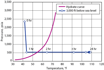
Sensitivity studies. To ensure that operations could succeed using the hot oil pumping rate and heater capacity available topsides, sensitivity simulations were performed for Well A-5 at different injection rates and temperatures to predict the time necessary for the tubing 3,000 ft below sea level-the location of the stuck tool string-to come out of the hydrate formation region. Simulations were performed for both shut-in and open-well scenarios. For shut-in well cases, the simulation included the trapped pressure in the wellbore above the hydrate plug, which worsened the wellbore condition relative to the hydrate dissociation curve; this caused a longer warm-up time. For open-well cases, the wellhead pressure was set at 500 psig. SIMULATION RESULTS The injection simulation for Well A-5 predicted that 7 hr would be required to move the entire tubing section above the orifice out of the hydrate-formation zone, assuming a 200°F injection temperature, an injection rate of 2 bbl/min. and wellhead pressure of 500 psig, Fig. 4. In contrast, to move just the tubing section at 3,000 ft-where the stuck tool string was located-out of the hydrate-formation zone, the predicted warm-up time was only 2 hr, Fig. 5.
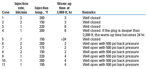
Sensitivity results indicate that the warm-up time is more sensitive to oil injection rate than to injection temperature, Table 1. The results also show that opening the well reduces the warm-up time by depressurizing the wellbore. For example, with the well open, an injection rate of 1 bbl/min and 150°F injection temperature yields a 4-hr warm-up time (Case 11), which increases to more than 24 hr if the well is closed (Case 5).
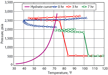
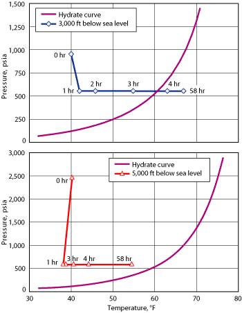
INJECTION OPERATIONS The danger of the hydrate plug shooting up the wellbore after being dislodged was determined to be minimal, due to fluids that were pumped into the tubing above the plug (glycol and crude oil for Well A-9 and Well A-10; methanol/calcium chloride mixture and crude oil for Well A-5). Well integrity issues mainly concerned the compatibility of the hot oil with the elastomers and possible asphaltene or paraffin precipitation in the annulus. A review of the type of materials present in the wellbore confirmed that all were compatible with hot oil. A review of the oil characteristics determined that asphaltenes were not likely to precipitate. To avoid any possible solid deposition in the annulus, the hot oil injection was followed by dry gas injection immediately after the hydrate plug melted. Dry gas injection was considered the simplest and fastest operation to flush the annulus before the well cooled down, since no additional equipment would be required. At Well A-5, several attempts were made to pump hot crude oil into the tubing-casing annulus using a rental thermal unit to heat the crude to 200°F. These attempts were unsuccessful because excessive gas flashing out of the crude oil caused the rental booster pump to cavitate. The operator then decided to use production equipment to get the produced crude oil entering the dry oil tank as hot as possible (in this case 135°F) and then inject the heated crude into the annulus using the pump-down pump on the platform. Based on the transient simulation results, the necessary equipment for hot oil injection operations, particularly the pump and production equipment, were assessed and found to be adequate to inject up to 1.5 bbl/min. at 125°F. The hot crude oil (125°F at injection) was pumped down the annulus through the orifice, into the reservoir at 1.5 bbl/min. After 12 hr of injection, the tool string became free and was tripped out of the wellbore. A transient simulation with the same injection rate and temperature was performed; it predicted 3 hr of warm-up time for the tubing section at 3,000 ft. The difference between the estimated and actual times may be attributable to the time needed to melt the hydrate plug, as well as other factors including the wellbore model’s simplicity and assumptions in the input data. At Well A-9, 120°F crude oil from production was injected into the annulus with the facility’s pump-down pump. The hot crude was pumped down the annulus through the gas-lift valve, about 6,600 ft below sea level, into the reservoir at 1.5 bbl/min. After 6 hr of injection, communication in the tubing was established by rising wellhead pressure, and the crude was able to be pumped down the tubing. After the operation, the crude was displaced from the annulus with gas-lift gas at 3.8 MMcfd to prevent crude cooling and paraffin deposition in the annulus and to keep from washing out the gas-lift valve. A subsequent transient simulation with the same injection rate and temperature predicted a 4-hr warm-up time for the tubing section at 3,000 ft. At Well A-10, 125°F crude oil from production was injected into the annulus with the pump-down pump on the facility. The hot crude oil was pumped down the annulus through the gas-lift valve, 5,200 ft below sea level, into the reservoir at 1.4 bbl/min. After several hours of injection, no communication was established in the tubing, so transient simulations were performed. At the same injection rate and temperature, the simulations predicted a warm-up time of only 4 hr for the tubing section 3,000 ft below the sea level. However, the section 5,000 ft below sea level was predicted to stay in the hydrate-formation region even after 58 hr of injection, Fig. 6. This is because as the hydrate plug becomes deeper, the ambient seawater temperature gets colder. Thus, it worsens the hydrate risk condition; i.e., it moves wellbore conditions on the pressure-temperature plot further to the left relative to the hydrate dissociation curve.
After 60 hr of injection, communication in the tubing was established and the crude was able to be pumped down the tubing. After the operation, the crude was displaced from the annulus using gas-lift gas at 0.4 MMcfd. As was the case for Well A-9, this was done to prevent crude cooling and paraffin deposition in the annulus and to keep from washing out the gas-lift valve. Comparing the simulation results with the actual time necessary to melt the plug indicates that the plug is located between 3,000 and 5,000 ft below sea level. PREVENTATIVE AND CORRECTIVE ACTIONS After review of the slickline operations, lessons learned were drawn. Among these, it was recommended that glycol be used as the fluid for all pressure testing, because it also serves as a hydrate inhibitor. Also, a quick-test sub should be used for wireline operations to minimize fluid loss into the wellbore when conducting lubricator pressure tests. Post-mortem analysis of the shut-in operations showed that insufficient AA LDHI had been injected due to problems in the chemical injection skid. In response, a multidisciplinary team was formed to revise the restart procedures after long-term shut-ins if inadequate AA LDHI was pumped. To prevent hydrate from plugging the well, the team recommended the following procedure be conducted after opening the SCSSV:
The revised procedure was implemented at other dry-tree wells that had been shut in at the same time as Wells A-9 and A-10 due to the hurricane with inadequate AA LDHI. Hydrate problems were not encountered when restarting these wells. Based on the remediation experience at Well A-5, it is recommended that crude oil, to be injected into the tubing-casing annulus for hydrate remediation, be heated to the highest temperature possible using production facilities, rather than using a third-party heater. This should avoid gas flashing that could cause the pump to cavitate. If production facilities cannot heat crude to the desired temperature, then diesel, water, dead crude or other fluid may be used, though it wasn’t required in this case. CONCLUSIONS Hot oil injection to the tubing-casing annulus successfully melted the hydrate plugs formed inside the tubing in all three wells. Thermal-hydraulic transient simulation of the wellbore was helpful in assessing the feasibility of hot oil injection for remediating hydrate plugs, particularly in estimating the required injection temperature and rate. Assuming that the wellbore model is accurate and all the input data in the simulation is correct, the melting time of the hydrate plug was found to be about three times as long as the warm-up time. Knowing the approximate location of the hydrate plug was helpful in assessing the likelihood of melting it. A revised well restart procedure was developed to minimize the likelihood of hydrate plug formation. ACKNOWLEDGMENT This article was modified from “Transient simulations assist hydrate remediation efforts in deepwater Gulf of Mexico dry-tree wells,” SPE 100750 presented at the SPE Asia Pacific Oil & Gas Conference and Exhibition held in Adelaide, Australia, Sept. 11-13, 2006. LITERATURE CITED 1 Bendiksen, K. H., Malnes, D., Moe, R. and S. Nuland, “The dynamic two-fluid model OLGA: Theory and application,” SPE Production Engineering, May 1991, pp. 171-180.
|
|||||||||||||||||||||||||||||||||||||||||||||||||||
- What's new in production (February 2024)
- Prices and governmental policies combine to stymie Canadian upstream growth (February 2024)
- U.S. operators reduce activity as crude prices plunge (February 2024)
- U.S. producing gas wells increase despite low prices (February 2024)
- U.S. drilling: More of the same expected (February 2024)
- U.S. oil and natural gas production hits record highs (February 2024)
- Applying ultra-deep LWD resistivity technology successfully in a SAGD operation (May 2019)
- Adoption of wireless intelligent completions advances (May 2019)
- Majors double down as takeaway crunch eases (April 2019)
- What’s new in well logging and formation evaluation (April 2019)
- Qualification of a 20,000-psi subsea BOP: A collaborative approach (February 2019)
- ConocoPhillips’ Greg Leveille sees rapid trajectory of technical advancement continuing (February 2019)

