SAND CONTROL
Reservoir formation failure and sanding prediction
for well-construction and completion design
Two
North Sea fields overcame sanding problems after detailed rock
mechanic analysis and completion designs tailored to the reservoirs’ limits.
Giin-Fa Fuh,
Ian Ramshaw, Kerry Freedman and Nabeel Abdelmalek, ConocoPhillips; and Nobuo Morita,
Waseda University
Sand production due to reservoir formation failure often causes significant
production loss, facility damage, and can lead to well shut-in after
continuous sanding-up. It is cost effective to generate a good well
completion design by running a series of computer simulations. Historically,
several completion methods were tried for a field. However, this trial-and-error
method required time, excessive cost and effort before the best sand
mitigation completion method was identified.
Our study showed that, if the reservoir rock strength and its variation
along depth were measured for each well, the conditions inducing sand
production could be predicted for each interval. Therefore, if permeability
distribution and oil and water saturations were measured for each well
in addition to the rock strength, the best completion method could
be identified without trial-and-error.
Our SAND3D program, a 3D finite element sand production and well mechanics
analysis system, has been developed and extensively field-applied over
15 years to predict and handle the onset condition of sand production
from the productive interval. This article provides details about our
approach and analysis procedures.
JUDY/JOANNE RESERVOIRS
The Judy/Joanne field is located in Block
30/07a in the North Sea’s
UK sector, within the central graben some 175 mi. east-southeast of
Aberdeen, Fig. 1. It is a Triassic gas-condensate field with a hydrocarbon
column down to 11,440-ft TVDSS. The development is borderline HPHT
with a calculated BHST of 320°F. The main reservoir is the Mid-Upper
Triassic-age Joanne sandstone. Hydrocarbons have also been proven and
targeted in the Middle Triassic Judy sandstone and the Upper Jurassic
Fulmar formation.
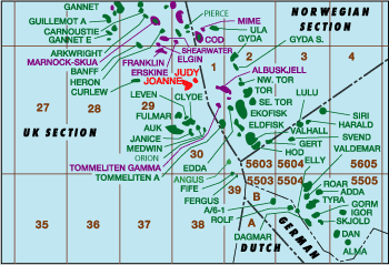 |
Fig.
1. The Judy/Joanne field is in Block 30/07a
of the North Sea’s UK sector. |
|
The field’s pre-Cretaceous wells
have been cased and perforated. Some of these are known solids producers
that have to be choked back to minimize solids production. To find
an improved completion solution for new wells, investigators examined
the problem using a systematic rock mechanics approach. Two well
cores from Well 30/7a-7 (Judy) and Well 30/7a-P3 (Joanne), provided
representative reservoir sandstone samples for sand strength determination
and sanding evaluation.
FORMATION STRENGTH
Both cores were sampled and tested using a manual load frame and a
penetrometer for unconfined compressive strength (UCS). Further samples
were selected from low-to-intermediate strength portions for triaxial
tests.
Judy sand strength has 2,000-7,100 psi or higher UCS, Fig. 2.
Nearly 50% of the samples tested had UCS lower than 3,000 psi. In the
weaker Joanne sandstone, 90% of the samples had UCS below 3,000 psi.
About 50% of Joanne sands have UCS from 770-1,500 psi. The P10/P50/P90
values for Judy and Joanne sand strengths are about 2,500/3,000/3,600
psi and 1,000/1,600/3,400 psi, respectively. Sand strength and reservoir
depth suggest sand production or sand failure during production, so
some control strategy is needed.
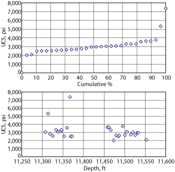 |
Fig.
2. Unconfined compressive strength work was
performed on Judy field’s sandstone cores. |
|
TRIAXIAL TESTS
Core segments were selected for triaxial
testing and multiple plugs were used to determine stress-strain relationships
and failure criteria. Stress-strain relationships were obtained at
five different confining pressures: 0, 500, 1,500, 3,000 and 4,500
psi covering the net stress range anticipated over the field’s
productive life. These data were then analyzed to define the non-linear
material laws and critical plastic strain failure limits for formation
failure and sanding prediction, Fig. 3.
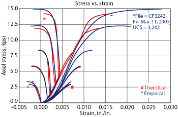 |
Fig.
3.
Stress-strain curve input helped characterize Judy sandstones. |
|
The analysis of stress-strain and rock
failure/yield data shows “cap” failure,
Fig. 4. Pore collapse failure would occur at high confining pressure
for the Joanne sandstone, since it has porosity of 25-32%. The
initial shear failure envelope is followed and bounded by a cap representing
the onset of pore collapse failure. For the yield envelope, J1 represents
the arithmetic sum of the three principal (normal) stresses, while
SQRT(J2) represents the generalized shear stress in 3D. Cap failure
was not detected and shear failure is projected for the Judy sandstone,
due to its tighter nature and 15-25% porosity.
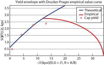 |
Fig.
4. The initial shear failure envelope for
Joanne sand,
UCS = 1,152 psi, is followed and bounded by a “cap,” representing
the onset of pore collapse failure. |
|
FAILURE ANALYSIS AND MODELING
Formation failure analysis provides an estimate of failure conditions
for particular reservoir rock strengths. Data were gathered and organized
into four categories for formation failure and cavity stability modeling:
- Rock strength
- Formation stress state
- Reservoir properties and flow
- Well geometry and completion
plan.
There is a more complex rock failure behavior and mechanism for the
Joanne sandstone, i.e., a combination of shear and pore collapse failures.
The sandstone exhibits normal shear failure mode resulting from reservoir
depletion.
Formation stresses were characterized using well logs, drill stem
test, leak-off test, core test, and drilling reports for field wells.
In the modeling, the average depths of 11,261-ft TVD and 11,621-ft
TVD were used for Joanne and Judy sandstone reservoirs, respectively.
The initial stress states are derived or estimated for overburden,
maximum horizontal and minimum horizontal stress gradients: Sv = 0.98
psi/ft; Shmax = 0.91 psi/ft; and Shmin = 0 .86 psi/ft. Likewise, the
pore pressure gradients of 0.736 psi/ft and 0.728 psi/ft were determined
for Judy and Joanne reservoirs, respectively.
Fluid and reservoir permeability was used to determine pressures throughout
the grid-blocks and nodes in the reservoir/wellbore system. That allows
for prediction of stress changes due to fluid flow and pressure changes.
Some of the properties used in the simulation include:
- K = 20 md (Joanne), 5 md (Judy)
- Hydrocarbon saturation = 21%
(Joanne), 15% (Judy)
- Gas gravity (relative to air)
= 0.74
- Reservoir temperature = 300°F (Joanne), 320°F
(Judy)
- Porosity = 30% (Joanne), 25%
(Judy)
- Pri = 8,200 psi at 11,261
ft TVD and 8,550 psi at 11,621 ft TVD.
Well geometries from conventional to horizontal
were investigated. Borehole inclinations range from 0° to 90°, and all cases with
inclinations less than 90° were considered conventional. All well
models used an 8½-in. borehole through the reservoir. This borehole
was cased or left open as required for the evaluation case. The conventional
wells were modeled with standard, randomly-oriented perforations and
with stress-oriented perforations for failure prevention.
Conventional well, standard perforation
cases used perforations with 0.4-in. diameter, 11-in. formation penetration
length, 6 spf density and 60-120° phasing. In these cases, no tie between perforation
phase direction and wellbore stress direction was made. Conventional
well, stress-oriented perforation cases used perforations with 0.4-in.
diameter, 11-in. formation penetration length, 2-4 spf density and
0°/180° phasing (0° up, 180° down). Both horizontal
and high-angle openhole well cases were evaluated for sand failure
potential.
SAND3D SIMULATION
Conventional well cases were run for reservoir rocks with different
sand strengths. UCS values of 3,242 psi and 1,152 psi are the lower
average sand strength values and represent the formation failure analysis
for Judy and Joanne sandstone reservoirs, respectively.
Conventional well, standard perforations. The finite element rock
mechanics simulator solves for whether or not failure would occur for
a given rock strength, pressure depletion and associated reservoir
drawdown pressures. Results are displayed as a failure envelope, Fig.
5.
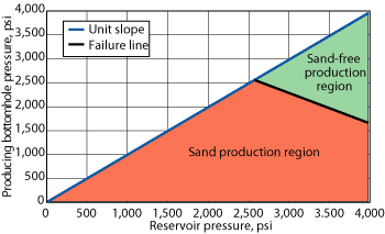 |
Fig.
5. The finite element rock mechanics simulator
solves for whether failure would occur for a given
rock strength, pressure depletion and reservoir drawdown
pressures. |
|
The failure plot is made from individual runs, accounting for reservoir
depletion and drawdown effects. The X-axis designates reservoir pressure,
and the Y-axis designates flowing bottomhole pressure. A unit slope
line runs diagonally across the plot, separating injection cases in
the upper half of the plot from positive drawdown production cases
in the lower half of the plot. A failure line is also shown.
In this example, the failure line intersects the unit slope line at
about 2,500 psi. The drawdown failure line is for a particular rock
strength, typically designated by the UCS value. The failure line represents
the reservoir and producing pressure conditions, which resulted in
formation failure for the rock UCS at the well and completion conditions.
Pressure conditions above the failure line (green) are expected to
allow sand-free production, while pressure conditions below the failure
line (orange) are expected to result in formation failure and sand
production.
Conventional well, oriented vs.
non-oriented perforations. The range of sand failure prediction results, considering
715-4,026 psi
UCS, for conventional wells completed with standard, non-oriented,
perforations at 11,261-11,621-ft TVD are summarized in Fig. 6.
The stronger rocks (above 4,026 psi UCS) could still fail, but failure
would occur at much lower pressure when the reservoir is further depleting.
This multi-rock plot contains a number of failure lines. Each represents
a particular rock type, designated by its UCS. They all indicate that
sand failure would happen early, i.e., within 16.4-22% or less
of the reservoir depletion, if the conventional well is completed with
standard (random) perforations. Field observation confirmed such early “solid
production” results.
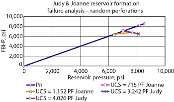 |
Fig.
6. The range of sand failure prediction results,
UCS 715-4,026 psi, for conventional wells completed
with standard, non-oriented, perforations at 11,261-11,621
ft TVD. |
|
Stress-oriented perforations in inclined wellbores produce a favorable
effect on rock failure conditions in the Judy at 11,621 ft TVD, Fig.
7.
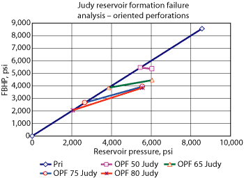 |
Fig.
7. Formation failure analysis for the most
representative Judy sandstone with UCS = 3,242 psi,
using wellbore angles of 50°, 65°, 75°,
and 80°. |
|
The stability condition improvements from
using stress-oriented perforations are significant. For example,
for a 50° inclined well, the depletion
failure (shear failure at drawdown pressure = 0 psi) could be delayed
by 1,400 psi, if stress-oriented perforations were used instead of
random ones. In the same manner, a delay of depletion-only sand failure
is increased (improved) by 3,300 psi, 4,500 psi, and 5,100 psi for
wells with 65°, 75°.and 80° hole inclinations, respectively.
However, there is also a significant limit
for high drawdown in the Judy reservoir as the failure envelope is
moving “upward” with
positive slope in the fluid flow regime. This indicates that the perforation
tunnels become unstable due to changing stress conditions. Similar
failure envelopes were obtained for Joanne sands, but envelopes become
a little more restraining in the drawdown portion. The Judy case is
slightly better than Joanne’s, since the “slope” is
milder, and it only becomes positive when hole angles increase to 65° or
higher.
The upward failure envelopes in the fluid
flow regime result from perforation tunnels becoming unstable. While
applying drawdown to the oriented perforations, the degree of directional
stress difference (Sv/Sh ratio) in the radial plane (tunnel cross-section)
would become large and “inhomogeneous” due to the continuous fluid drawdown
and large fluid flow. Therefore, if the rock itself or its cementation
strength is not strong enough, the tunnel becomes weaker during the
drawdown and pushes the curve upward, limiting the “sand-free” drawdown.
The stress ratio and perforation angle affect the overall stability
of the perforation tunnel. The stability enhancement due to drawdown
is most evident for stronger rocks and for a larger stress difference
or Sv/Sh ratio. Other factors such as the rock non-linearity could
also play a role in this special effect.
Openhole horizontal and high-angle
wells. A similar failure analysis was conducted for both Judy and Joanne
sandstone reservoirs. The objective was to quantify formation stability
compared with other completion options. Results of the openhole horizontal
and high-angle well failure modeling work are provided in a failure
envelope. The hole angles analyzed are 90° (horizontal well) and 65°.
ORIENTED PERFORATION
While our work on the Judy/Joanne reservoir
formation failure analysis and sanding prediction was in progress,
the new pre-Cretaceous well from the Judy platform, P20, was set
for a March 2005 spud date. The Joanne sandstone’s relatively low UCS values and the fact the
P20 was to be completed with an 80° wellbore deviation were sufficient
to investigate downhole solids control solutions.
Two options were considered: standalone openhole screens and oriented
perforations. Given the early results of our formation failure analysis
and sanding prediction, and the success that ConocoPhillips UK Ltd
had running screens in the southern North Sea since 1995, the use of
screens was the preferred option. However, given that there had been
no previous study work performed by the J Block to select an optimum
drill-in fluid along with the long lead time on the base pipe required,
this was not a viable option.
As an alternative, the Halliburton G-Force
oriented-perforation system was chosen. The guns run were 3 1/8-in.,
4 spf with 0°/180° phasing.
This system was chosen based on our previous success in an Indonesian
field, along with the ease of system deployment versus other perforation
systems. The Well P20 completion was a 5½-in. monobore with
a sliding-side-door/PBR/production packer/tailpipe assembly and a cemented
production liner. Prior to running the upper completion, the guns were
deployed on drill pipe in an overbalanced, clear caesium formate brine.
There were 1,200 ft of guns run across the Judy formation and 800
ft of guns run across the Joanne with about 600 ft of spacer between.
On successful perforation, the upper completion was run using overbalanced
clear fluid. With the completion landed and Christmas tree installed,
the wellbore and annulus were circulated-out to inhibited seawater
and the well was ready to be brought into production. The well was
completed in September 2005.
As an evolution to the downhole solids control philosophy now being
adopted on the Judy platform, studies are developing a standalone screen
solution for the next Judy well (P21). The same upper completion will
be run (minus the sliding side door). However, rather than using a
cased production liner with oriented perforations, the operator hopes
to complete it with 4-in. openhole sand screens.
WELL P20
When P20 was brought into production, its performance was above expectation
with initial rates of 13,000 bopd and 33 MMcfd at 31% choke. For reservoir
management reasons, the well continues to be operated on this choke
setting. Solids production is monitored using a Cormon intrusive probe
mounted on the P20 flowline.
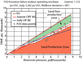
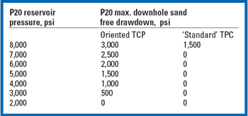
Figure 8 shows the P20 failure envelope developed from the SAND3D
modeling analysis. The green area shows the safe operating zone. The
orange zone indicates that sand production is likely. The results of
the operational envelope are summarized in the table below the chart
and are compared with the standard TCP case.
|
Fig.
8. Well P20’s failure envelope’s
positive slope restricts drawdown to avoid early sand
failure. |
|
The “positive” slope of the
failure line restricts drawdown so as not to induce early sand failure.
The yellow dots are data points showing how the well was operated
over a six-month period, since being brought online (through end
March 2006). There were initial activity signs on the intrusive probe
when P20 was started, which were attributed to wellbore cleaning.
Since then, there has been no evidence of solids production. As can
be seen from the two latest data points, we are producing solids
free, despite venturing into the orange zone.
EMBLA FIELD RESERVOIRS
Embla Field is in PL018 license about 300 km southwest of Stavanger
in the Norwegian North Sea. Over time, several field wells exhibited
abnormally high production decline, and formation failure was considered
a likely source. Pressure transient and production inflow revealed
that perforation tunnel collapse could cause a pressure loss up to
99% of total drawdown.
Embla reservoirs are at ±13,250 ft TVDSS. The Devonian-age
D1 and D3 sands are heterogeneous with thick, multilayered sand-shale
sequences and up to 1,000 ft of hydrocarbon column. However, the Permian
age sand is a high net-gross reservoir. These sands have 1-35
md and produce 42° API oil with 1.8-2.2 Mcf/bbl of gas. The
zones have an average reservoir pressure of 12,200 psi and temperature
of 325°F. Wells were drilled at shallow angles (up to 30°)
and are completed conventionally with 6 or 12 spf, non-oriented perforations.
FORMATION STRENGTH
Three well cores from Wells 2/7-21S, 2/7-23S,
and 2/7-26S were tested. Sand strengths varied from 1,800-7,000 psi UCS. Reservoir sands
are generally strong and competent, with the majority ranging from
3,000-5,000 psi UCS. The sand strengths are relatively stronger
because there are more fine-grained and tight rocks. With an HPHT well
and a deep reservoir, there is good potential for sand failure, especially
for sands with strengths below 3,500 psi UCS.
In the same manner as Judy/Joanne field,
multiple plug samples were taken for triaxial tests, covering sand
strength groups from 3,030-5,690
psi UCS. Unlike Joanne sands’ cap failure, only shear failure
mode developed for Embla sands, due to its lower 12% average porosity.
The stress gradients for the Embla reservoirs are derived and estimated
at: 1.02 psi/ft Sv; 0.95 psi/ft Shmax; and 0.91 psi/ft Shmin.
A range of well geometries from conventional
to horizontal were investigated along with perforations. All models
used an 8½-in. borehole
through the reservoir. Failure lines show that rocks with 1,800 psi
UCS should have shear failure when the reservoir pressure drops from
Pri = 12,191 psi to 7,491 psi (38.6% pressure depletion). Beyond this,
sand production occurs for all drawdown conditions and field observations
agree. Embla sands with an average 3,455 psi UCS were more stable than
the lowest UCS 1,800 psi rocks. Depletion-only failure can initiate
when the reservoir pressure drops to 6,091 psi (50.0% pressure depletion).
Stress-oriented perforations in inclined
wellbores also produce a favorable effect on Embla rock failure conditions,
i.e., the higher hole inclination the better. All failure lines show
a “negative” slope.
The Embla sandstone is fundamentally stronger than Judy/Joanne. Therefore,
Embla drawdown is not as restricted as for Judy/Joanne reservoirs.
Sand failures are independent of well inclination angle with random
or arbitrary perforations. A significant percentage of random perfs
are incorrectly aligned. However, the majority of randomly-perfed tunnels
would fail above 40-50% depletion.
Modeling indicates that top/bottom-oriented
perforations could delay sand failure, especially at wellbore inclinations
above 40°. When
hole inclination reaches 70-75°, there would be little or no sand
failure, even if reservoir pressure was fully depleted. This is due
in large part because, at higher well angles, oriented up/down perfs
align somewhat parallel to the maximum stress direction. At 60-75° hole
angles, oriented top/bottom perforations offer a significant increase
of “allowable” reservoir pressure depletion in the weakest
rock.
HORIZONTAL AND HIGH-ANGLE CASES
Rocks with a reference UCS of 1,800 psi
and 3,455 psi are all likely to produce sand at some point. As expected,
an increase in hole angle induces sand failure sooner during the
well’s
productive life. Likewise, the stronger reservoir rocks would see
sand failures at much later stage.
For a higher 3,455 psi UCS in the same horizontal openhole completion,
sand production could start when the reservoir pressure is depleted
by 5,500 psi (45.1% original pressure); this is a 10.6% improvement
in drainable reservoir pressure without initiating sand failure.
In wells with an openhole inclination
angle at 60° and 50°,
pressure depletion by 41.0% and 46.0%, respectively, could cause sand
failure in the low-strength portion of the Embla reservoir (1,800 psi
UCS).
SCREEN FAILURE/STABILITY
The use of stand-alone screens was considered
as a completion option in an openhole high-angle or horizontal Embla
well. We assumed that a 5.62-7.66-in. OD screen could be used for the 8½-in.
open hole.
The larger diameter minimized flow plugging
and screen collapse problems. However, we assumed it would be installed
in a highly inclined well, so we select a 6.13-in. OD screen that
left a 1-in. clearance between the outer shroud and borehole annulus.
Numerical analysis indicated that an openhole completion could induce
sand failures in the weakest sand interval at well inclinations as
low as 30°.
The results of Pipe3D analysis show that standard N-80 or J-55 base
pipe would remain stable at abandonment reservoir pressure as low as
500 psi. It is safe to use the commercially available stand-alone screens
for Embla, regardless of angle.
The issue of formation permeability is a critical factor in determining
the effectiveness of a stand-alone screen. If the formation permeability
is less than 100 md like the most Embla reservoirs, then the skin damage
per openhole foot is very small.
EMBLA WELL DESIGN
Based on the sand failure study, cost
evaluation and completion design parameters, engineers decided that
the newest Embla well would penetrate the reservoir with a 60° wellbore and be complete with a cased
hole and stress-oriented perforations. The well angle through the reservoir
was later revised to 50-55° because of HPHT challenges and logging
tool limits.
Well 2/7-D-07’s construction program
was designed to achieve the 50-55° well angle. The well was turned
to the ±50° deviation
at about 12,000-ft TVD and held there to 15,196-ft TVD. Wireline conveyed
the 3 3/8-in. OD eccentrically-weighted perforating guns to orient
the charges at 0°/180°. The guns were loaded at 6 spf with
deep-penetrating charges.
Drilling and completion went smoothly
and Well 2/7-D-07 reported no major problems. The initial completion
included 426 ft of the pay section and 10 perforating runs were required.
The gun system included a shot orientation detection device to record
the gun’s orientation
at detonation time and data indicated the orientation system was functional.
The well was placed on production in December 2005. Based on the limited
production to date, it is still too early in the well life cycle to
determine the success of the stress-oriented perforation completion
strategy.
CONCLUSIONS
Our approach to the well construction and completion design uses a
systematic reservoir formation failure, sanding prediction and screen
failure analysis, based on our North Sea operational cases.
Reservoir rock strength and failure behaviors are key elements to
determine well performance, completion scheme selection and effective
sand control during reservoir depletion. The clear difference in sand
failure mechanism between the Judy/Joanne and Embla reservoirs governed
the choice of completion design. The effectiveness of the stress-oriented
completion technique in high-angle wells is good for many different
rock types, but may not be ideal for others where control of sand failure
or production becomes difficult or restrictive during reservoir production
and depletion.
The use of a systematic SAND3D/Pipe3D analysis offers a realistic
and reliable approach to evaluating and optimizing well completion
design options, when sand production and wellbore or perforation collapse
are considered or evaluated as a risk. Field experience supports this.
Periodically taking reservoir cores is
a worthwhile investment for future design of a well’s construction
and completion scheme to achieve optimum well productivity with effective
sand control or management and prolonged well life. 
ACKNOWLEDGEMENTS
The authors thank ConocoPhillips’ management and its North
Sea unit partners Total, ENI, Norsk Hydro, Statoil and Petoro for
Embla (under License PL018), as well as British Gas and ENI for Judy/Joanne,
for permission to publish. We appreciate the review and constructive
suggestions by many colleagues, particularly Hilde Alexandersen and
Craig Stewart. This article was prepared from SPE103244 presented
at the 2006 SPE Annual Technical Conference and Exhibition held in
San Antonio, Texas, September 24-27, 2006.
BIBLIOGRAPHY
1 Morita, N., et al, “Realistic sand-production
prediction: Numerical approach,” SPE Production Engineering
Journal, v. 40, n. 9, p 15-24, February 1989.
2 Morita, N., et al, “Parametric study of sand
production prediction: Analytical approach,” SPE Production
Engineering Journal, v. 5, n. 1, pp. 25-33, February 1989.
3 Morita, N. and G. F. Fuh, “Prediction of
sand problems of a horizontal well from sand production histories
of perforated cased wells,” SPE 48975, presented at SPE Annual
Technical Conference and Exhibition, New Orleans, La., September
27-30, 1998
4 Burton, R. C., et al, “Application of reservoir
strength characterization and formation failure modeling to analyze
sand production potential and formulate sand control strategies for
a series of North Sea reservoirs,” SPE 48979, presented at
SPE Annual Technical Conference and Exhibition, New Orleans, La.,
September 27-30, 1998.
5 Fuh, G. F., et al, “Pre-Cretaceous Judy/Joanne
reservoir formation failure analysis for sanding prediction and well
completion design,” ConocoPhillips Report, WBT.550077.PO,
2005.
6 Fuh, G. F., et al, “Embla reservoir formation
failure analysis for sanding evaluation and screen stability study,” ConocoPhillips
Report, WBT.520148.PO, 2005.
7 Fuh, G. F. and N. Morita, “Development of
Pipe3D model for casing and/or screen stability analysis of sequential
loading during reservoir depletion and drawdown,” ConocoPhillips
Report, WBT.CU5711.PO., 2004.
8 Morita, N., et al, “Collapse resistance of
tubular strings under geotectonic load,” SPE 95691, SPE Annual
Technical Conference and Exhibition, Dallas, Texas, October 9-12,
2005
9 Bruno,
M. S., “Geomechanical analysis and decision analysis for
mitigating compaction related casing damage,” SPE 71695, SPE
Annual Technical Conference & Exhibition, New Orleans, La., September
30- October 3, 2001.
|
THE AUTHORS |
|
Giin-Fa
Fuh earned a PhD degree in rock mechanics from the
University of Wisconsin-Madison. He has 29 years’ experience with
ConocoPhillips providing engineering services and technology
development to the company’s worldwide business units.
His projects concern drilling and completion-related wellbore
stability, formation failure/sanding prediction, wellbore
strengthening and lost circulation prevention, reservoir
compaction and subsidence prediction, and formation fracturing.
Dr. Fuh is a ConocoPhillips engineering fellow in Upstream
Technology, Houston, Texas. |
|
| |
Ian
Ramshaw earned a BS degree in chemical engineering
from Cambridge University. He began his career as a service
company field engineer and has been with ConocoPhillips since
2001 working in various roles. Ramshaw is the ConocoPhillips’ North
Sea J-Block asset production team leader, based in Aberdeen. |
|
| |
Kerry
Freedman earned a BS degree in petroleum engineering from Louisiana
State University. He is a staff production/completions engineer
for ConocoPhillips’ North Sea business unit. |
|
| |
Nabeel
Abdelmalek earned a BS degree in chemistry and an MS degree in petroleum
engineering from the University of Pittsburgh. He has 30 years’ experience
in engineering with ConocoPhillips, providing integrated technical
support for field developments around the world, well design,
performance analysis and field production optimization. Abdelmalek
has specific interests in reservoir, production and well completion
engineering. |
|
| |
Nobuo
Morita earned MS and PhD degrees in petroleum engineering
from the University of Texas at Austin. Dr. Morita was a research
fellow for Conoco and is now a professor at Waseda University,
Japan, in the Resources and Environmental Engineering department. |
|
|


