Technology from Europe: France
Subsea slug catchers provide flexibility for deepwater field developments
Moving slug catchers to the seabed frees floating-facility space and weight, creating more topside processing options.
St�phanie Abrand and St�phane Anres, Saipem; Christian Rueda, Saibos; Constant Tsouza, Total E&P
Subsea processing technologies have moved forward quickly in the last few months. Several projects including subsea boosting, subsea separation or subsea gas compression are foreseen or already sanctioned.
The development of gas fields usually requires the use of slug catchers. For large flowrates or when the length of the multiphase line is long, this equipment can be very large and require heavy structures, up to several thousand tons. Installing them on the seabed would be preferable to installing them on topsides or at shore.
The first Subsea Slug Catcher (SSC) was installed in 1985 by Texaco on the Highlander field in the North Sea. This equipment, in 550 ft (168 m) of water, is used for a limited slug volume.
Total E&P recently awarded Saipem an SSC feasibility study, covering very large slug volumes and water depths. This article discusses using such systems for several offshore field development scenarios like new stand-alone developments, subsea tie-backs to existing platforms or tie-backs to shore.
The main function of a slug catcher is to collect the liquid coming from a gas line and avoid the gas-processing system, which may be limited or bottlenecked by liquid. So, the slug catcher has to handle a defined liquid volume, while separating the gas and routing it through the gas-processing system.
On topsides or onshore, a slug catcher could be so huge that it could be detrimental for new tie-ins or very constraining for platform/plant designs. With a subsea design, this space could be re-allocated, giving higher design flexibility. Moreover, all the requirements for safety and fire fighting linked to this equipment are released.
A slug catcher, subsea or not, is made of two parts: The first separates gas from liquid, and the second holds the liquid. The first is sized based on the process requirements for gas separation, and the second is sized by the liquid volume handled, Fig. 1.
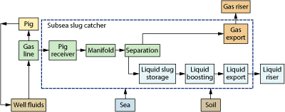 |
Fig. 1. Functional requirements for a subsea slug catcher include gas separation and liquid storage. The functions can be designed into one unit or separated into two or more devices.
|
|
Liquid can be produced through different modes:
- Continuous liquid production under normal steady-flow conditions
- Intermittent or transient liquid production, when flowrates vary (slugging)
- Pigging or sphering, when liquid is displaced from the pipeline into the slug catcher in a relatively short time.
For each study case, many geometries have been proposed for a slug catcher: a single vessel, for small slug volumes, and piping arrangements specifically for bigger sizes. For this option, several configurations could be proposed depending on space limits. The main rule to follow for the liquid-containing equipment is to provide a minimal slope to ensure good liquid flow.
DESIGN
A slug catcher can be divided into two main functions (excluding the boosting function): separation and storage, Fig. 2. Several designs have been proposed:
- Conventional multiple-pipe slug catcher (several fingers, each with separation and storage functions)
- Divided separation and storage: separation is done with one vessel (pipe or separator) along with several storage solutions (pipes, vessels, tanks, etc.)
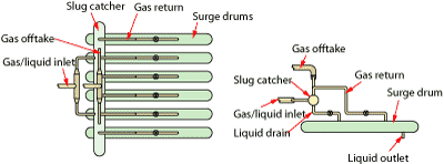 |
Fig. 2. Typical slug catcher arrangement includes several surge drum �fingers� to separate gas and store liquid.
|
|
Separation process. The length of the separation device between its inlet and its gas outlet is determined by the desired settling and separation efficiency. Droplet setting can occur by gravitation when flowing at low velocities, typically less than 2 m/s, and provided there is sufficient residence time.
The calculation model used to size the slug catcher is based on rules found in the literature. It is based on experimental curves giving an L/D ratio vs. separation efficiency and droplet size. An efficiency of 99% was the base case and the smallest droplet size was chosen. To calculate the gas velocity, a cross-section ratio from the inlet gas velocity was used. This procedure is used as well for pipe-like or vessel-like separation.
Storage. The storage volume of a slug catcher corresponds to the maximum liquid volume it has to hold. It must intercept the maximum possible slug size emerging from the flowline. It should also contain a buffer volume of condensate to guarantee liquid supply to topsides facilities downstream of the slug catcher.
The storage volume is designed to handle the slug volume. The worst case (bigger slug based on a frequency of 1/1000) is considered for design purposes. A buffer of 10% of the slug volume was assumed. This is an arbitrary value that must be discussed, depending on the topsides facilities. In a conventional multiple-pipe slug catcher design, liquid misdistribution is considered, assuming that the most heavily loaded finger receives 20% more than in the even-distribution case.
In designs where the separation and storage functions are divided, the whole volume (slug + buffer) is held by one large vessel, several vessels or pipes. No misdistribution is taken into account. There is only one gas outlet from the separation device, connected to all storage devices, so that liquid in the gas outlet indicates that all the storage devices are full. All storage devices are connected to one another by an inlet manifold and a liquid outlet manifold for pressure equilibrium.
Boosting. Liquid boosting was estimated to deliver the pressure required for topsides. Boosting is also required to eliminate the liquid during specific operations, such as pigging.
Mechanical. For each case, the internal design pressure assumed was 240 bars, the reservoir pressure. To determine the pipe (or the vessel) wall thickness, the API RP 1111 standard for burst and collapse was used for preliminary sizing.
Burst (240 bars minus hydrostatic pressure) and collapse (with 1 bar internal pressure) calculations were performed, and the maximum wall thickness was considered for the preliminary weight estimate.
Modularization. Since the system will be installed subsea, critical equipment should be retrievable. This means that the subsea station should be modularized to allow easy retrieval of each part. Intervention vessels should be able to handle the modules, so that installation vessel mobilization is not required.
OPERATING STRATEGY
To prevent and control hydrate formation, the general strategy selected is to inject Mono-Ethylene Glycol (MEG) at wellheads. Thus, there is no hydrate issue during normal flowing conditions.
During production when low liquid quantities are produced, liquids can segregate and potentially form hydrates in the storage part of the system. During shutdown, a recycling loop, working with the boosting system, can overcome this hydrate issue by keeping the liquid mixed with MEG.
If a shutdown occurs and if power can be sustained to the pump, even at a lower pumping rate, then MEG can be kept mixed with the liquid, preventing hydrates. However, the pump is shut down in most cases, allowing the liquid phases to separate. Depressurization could then be required to keep condensate outside of the hydrate zone. Depressurization may not be required for shallow water cases where hydrostatic pressure is limited.
CASES STUDIED
Four different cases were investigated. Flowing calculations were performed to size the diameter and estimate the slug volume. The aim was to have wide variation among the cases to propose different solutions for the slug catcher design. The data are summarized in Table 1.
| TABLE 1. Cases studies |
 |
|
Depending on the volume considered, several designs were proposed. These designs offer options that can be used on different fields, highlighting the main constraints and limitations, such as water depth and soil characteristics.
For Cases 1, 3 and 4, the design criteria governing the shell’s thickness is the burst pressure. In Case 2, the shells are sized to resist to the collapse pressure. In all cases, the shell weights do not depend significantly on the proposed design. For each study case, the choice of design was governed by fabrication, installation, available seabed space and operational constraints.
Case 1. The small (100 m3) storage volume in Case 1 does not justify a divided storage function with several parts. This is why the “single vessel” was selected. This design leads to excessive vessel sizes and wall thicknesses for the other cases.
Cases 2, 3 and 4. For the remaining cases, the choice was from among several configurations. Only Cases 2 and 4 are described, since they are the extremes. Case 2 is located in deepwater, so a compact solution—a “beams” configuration—is preferred for easier installation and handling operations. It uses the same principle as fingers, but with piping superposed, Fig. 3.
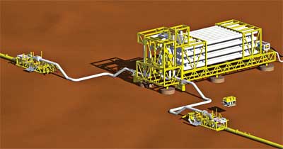 |
Fig. 3. The �beams� configuration has many �fingers� ganged as a unit.
|
|
For Case 4, with a huge slug catcher volume, a solution maximizing pipelaying was selected, Fig. 4. A 42-in. pipe is installed after the first separation vessel to store liquid, and the boosting system is installed at the end of the pipe. This configuration is highly dependent on mudline topography, and especially on its slope. Engineers proposed studying an alternative to installing the slug catcher as a single structure. This SSC is more compliant with shallow water, since the pipe has a large diameter. A deepwater installation would be very challenging.
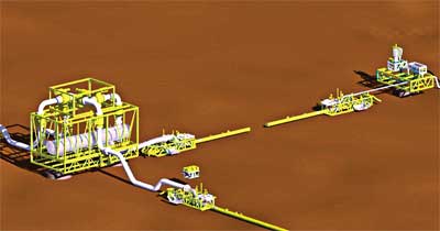 |
Fig. 4. The pipe configuration for Case 4 uses a long pipe section as the storage vessel.
|
|
The main slug catcher parts are retrievable. The structure is divided into several modules for valves, gathered as a manifold, and for the boosting system. Tables 2 and 3 give the weight and size of installed structures for each case (foundations excluded).
| TABLE 2. Weight summary |
 |
|
| TABLE 1. Size summary |
 |
|
INSTALLATION
Case 2. The SSC is installed on top of its foundation, Fig. 5. The foundation will be previously deployed by the same vessel. The vessel proposed to perform this (SSC, foundation, umbilicals and spools installation) was the Saipem 3000 vessel or equivalent. This vessel meets the functional requirements developed during the study. The SSC, along with the suction caissons or the suction piles, is transported to the site by a cargo barge (CB).
 |
Fig. 5. Typical installation includes (a) setting the suction pile, (b) installing the manifold, then (c) connecting the jumper(s).
|
|
The following steps are performed during installation:
- Connect the main crane and A&R winch to SSC rigging (minimum load is taken on the crane to tighten rigging and remove all sea-fastenings)
- SSC is lifted to 5 m above CB deck to move the CB and deploy the SSC at 65-m water depth
- SSC weight is transferred from the main crane to the A&R winch; the crane hook is disconnected and returns to its initial position
- SSC is lowered to 30 m above the seabed. The heave compensation is activated, and the SSC is lowered to about 6 m above its foundation with ROV survey and orientation control
- When all alignment checks are performed, the final lowering occurs; the rigging is disconnected and recovered with the hook crane when close to surface.
Case 4. A Derrick-Lay Barge (DLB) with high lifting capability would be required (separator module weight in air is 750 t) as well as a Pipe-Laying Barge (PLB) that can work with high tension in classic S-lay (about 200 t tension). For this reason, depending on contractor fleet capability, two vessels would be necessary for this work. Deploying a PLB, such as the Castoro 6 or equivalent for pipelay, and a derrick barge or DLB, such as the Castoro 8 or equivalent for lifting-in-air and lowering-in-water operations, makes this alternative the most efficient installation method. A multi-service vessel is used for spool installation and umbilical lay.
The procedure for structure installation (separator and boosting systems) is equivalent to those described for Case 2. For pipe-laying, conventional S-lay procedures are used, Fig. 6.
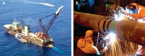 |
Fig. 6. The derrick-lay barge Castoro 8 (left) using the S-lay welding method (right).
|
|
INSPECTION
The intervention program and frequency will be based on engineering and on in-service behavior or abnormalities. The SSC inspection philosophy is similar to that for flowlines, considering that the SSC is mainly composed of pipes or vessels. Specific inspections would be performed on the pump as active equipment.
The subsea station will be permanently monitored through sensors (pressure, temperature, flowrate etc.) to detect any failure or abnormality. Periodic visual inspection is scheduled to prevent and detect any connector leakage (on the same basis as a manifold).
MAINTENANCE
The main objective of maintenance is to sustain system availability and preserve the integrity of physical assets. Maintenance is related either to preventing equipment failure (preventive maintenance) or to restoring equipment to service after breakdown (corrective maintenance). Corrective maintenance is carried out after fault recognition and is intended to put an item back into service, so it can function as required.
Maintenance does not require that the system or sub-system be taken out of service, whereas repair does. Maintenance can be performed in situ; repair cannot, since it involves replacement.
Planned maintenance includes maintenance on caps, valves and cathodic protection.
Very few maintenance operations can be performed without SSC shutdown; other SSC interventions are treated like repairs, even if they can be done without failure or abnormality detection on the SSC.
REPAIR
The SSC maintenance philosophy is to run to failure or to strong indication of failure, and then replace the unit with a complete spare, which is readily available on relatively short notice. Repair will normally take place with removal of a system unit from service, followed by shutdown and flooding before the repair intervention. Since repairs to be performed are likely to involve replacement of several elements or equipment sub-units, the operation to be carried out will require significant preparation and planning, comparable to the tasks undertaken at the time of installation.
In this global inspection-maintenance-repair philosophy, special attention should be paid to active components such as pumps, where specific maintenance could be required.
CONCLUSION
This study demonstrates the feasibility of SSC for shallow water (including very large capacity units—4,000 m3) and also for deepwater applications. The screening showed wide design flexibility, so that the system can be adapted to a diversity of field configurations.
The system is considered ready for a subsea application, since there is no need for new development: The qualification required is limited. The main challenge still remains in the operability and availability guaranteed by major equipment reliability, such as pumps.
Subsea slug catchers will open new opportunities in field development architectures, either to facilitate the tie-in of new production on existing congested platforms, or to reduce topsides weight on new fixed or floating platforms. Also, large slug catchers located at onshore terminals could be relocated to shallow water in areas where earth work is expensive or not possible due to environmental constraints. 
ACKNOWLEDGEMENTS
The authors and Saipem thank Total for its permission to publish this article.
BIBLIOGRAPHY
Dover, S. and M. T. Cooling, �The Highlander field�A year's operating experience,� SPE 16532, Journal of Petroleum Technology, February 1990.
Shotbolt, K., �Methods for the alleviation of slug flow problems and their influence on field development planning,� SPE 15891, presented at the European Petroleum Conference, London, October 20-22, 1986.
Smith, G. D. and G. H. Batcheler, �Overview of the Highlander field development,� SPE 13970, SPE Production Engineering, November 1987.
|
THE AUTHORS
|
|
Stéphanie Abrand earned an engineering degree from Ecole Centrale de Marseille in 2002. Abrand joined Saipem in 2002 as part of the Offshore Technology Development division, where she is a project engineer. She has worked on tensioned risers, insulating materials, a deepwater tender for Saibos division and subsea production-system studies.
|
|
|
Stephane Anres earned a BS degree in engineering from Ecole Centrale de Marseille and an MS degree from Carnegie Mellon University. He joined Saipem in 1990 and is currently project manager within the Offshore Technology Development. Anres has extensive experience in deepwater development conceptual studies for floating and fixed platforms, as well as risers and flowlines. He has been in charge of several preliminary studies for subsea processing, focusing on field architecture and subsea process equipment.
|
|
|
Christian Rueda earned a BS degree from the Civil Engineering School in Reims, France. He has over 29 years’ experience in offshore pipeline installation as design engineer, project engineer and engineering manager in ETPM and Bouygues Offshore Co., where he managed the Pipeline Section. He participated in the design and construction of the Saipem FDS, a deepwater installation vessel, then joined the Girassol UFL project as installation engineering coordinator. Since 2002, Rueda has been deepwater method manager within Saipem’s Saibos Division.
|
|
|
Constant Tsouza earned a degree in mechanical engineering from Institut Francais du Petrole. He joined Total in 1985, where he works in drilling, completion and subsea facilities. Tsouza is working in Norway as a senior petroleum architect.
|
|
|


