Horizontal drilling with liner provides savings
Pemex saved 40 days and $5 million, drilling its largest inclination ever with DWL.
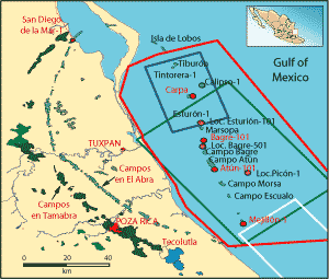
DRILLING TECHNOLOGYHorizontal drilling with liner provides savingsPemex drilled its largest inclination ever with DWL, saving 40 days of NPT and $5 million in the El Abra formation.Agust�n Jardinez Tena, Mart�n Terrazas, Renato Gami�o Ramos, and Victor M. L�pez Solis, Pemex E&P; Eduardo D�az, SPE, Hydril Co.; and Mike Fisher, Weatherford Drilling in the Cretaceous El Abra formation in Mexico’s GOM has proven costly and time consuming because of the difficulty in detecting natural fractures in the limestone formation. This difficulty is caused by the erosion of the formation’s top layer, which was originally reef. Moreover, the differential pressure between the Tertiary layer and El Abra results in several problems, such as lost circulation, stuck pipe, hole cave-ins and bad casing cement jobs. Operator Pemex responded by applying rotary Drilling-With-Liner (DWL) to cut a high-angle hole to the target depth, cement the liner and drill out the following interval horizontally, steering in the reservoir. GEOLOGY Eight fields have been developed in the offshore Faja de Oro or "Golden Lane"-Arrecife Medio, Isla de Lobos, Tiburon, Bagre, Atun, Morsa, Escualo and Marsopa-for a cumulative production of 210 million boe. These fields have produced light crude of 30–40° API from the Middle Cretaceous El Abra limestone. In May 1972, the Carpa 1 well was completed, on a structure detected with 2D seismic. This well produced from El Abra formation, which was found at 8,013 ft. In the well’s formation test, rates of 503 bopd of 33° API light crude were recorded together with 188,000 cfd of associated gas. From 1996 to 1997, 350 mi2 of 3D seismic from the Faja de Oro offshore was acquired, revealing that the Carpa 1 well was on the western flank of a high that formed a depositional paleo-relief-type stratigraphic trap modified by erosion. This interpretation also allowed a better choice for the location of the Carpa 101 well, which found the El Abra top 121 ft higher than Carpa 1. The Carpa 101 well was drilled and completed from 7,865 to 8,102 ft and plugged due to borehole instability. An openhole sidetrack drilled a horizontal lateral into the formation. The well produced at a maximum measured rate of 4,814 bopd of 32° API and 613,000 cfd in the flow tests. The well was shut down awaiting the production export pipeline. Location. Carpa field is on the Mexican Continental Shelf of the Gulf of Mexico, 19 mi off the coast of northern Veracruz, between the Tuxpan port and the Tamiagua lagoon, at a water depth of 154–174 ft. Geologically, it is located on the eastern edge of the Tuxpan Cretaceous shelf, in the El Abra play within the Tiburón-Esturión area, Fig. 1.
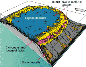
Structural geology. Seismic interpretation of the Lankahuasa Norte cube visualized a paleo relief of the El Abra formation, forming an elongated structure pointing toward Carpa field. The structure is part of a paleo relief set aligned north-south, which is crossed by east-west canyons. The structure points toward the Tamabra formation, which is Middle Cretaceous, Fig. 2.
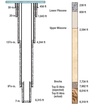
The sedimentary column cut by the well ranges in age from Middle Cretaceous to Cenozoic. The reservoir rock is post-reef facies, made of carbonate sands, represented by miliolid packstone and grainstone. These are the dominant facies in the producing sequence offshore Faja de Oro. The reef-front facies have only been found in the southern portion, at the Percebes 1 and Ostiones 1 wells. The diagenetic process controls rock quality. Reservoir seal. The seal for the El Abra reservoirs is Miocene shales. Mioliolid packstone and grainstone comprise the reservoir, which lies at 11,808 ft with a net thickness of 131–348 ft. Porosity is about 18% and permeability ranges from 70 to 3,000 mD. The oil reservoir is associated with a very active aquifer, and data from other fields shows that pressure decline is almost null. WELL HISTORY Carpa-7 and Carpa-101 wells are on a Sea Pony-type platform 1,312 ft from the platform where Carpa-3 and Carpa-55 wells are located. Carpa-101 was drilled in October 2002. In the original borehole, 7-in. casing was run and cemented at 7,865 ft. After that, drilling was performed with a 5 7/8-in. bit to 8,101 ft with an 8.8-ppg mud. The top El Abra was detected at 7,960 ft. A Drill Stem Test (DST) was performed in openhole and no flow was observed. A 5 7/8-in. bit was returned to hole, but found resistance at 7,875 ft. The borehole was reamed to total depth; cave-ins and mud losses were observed. A 3½-in. liner with inflatable packers was set at 8,016 ft. The well came online without production. A whipstock was set and a window was cut in the 7-in. casing at 7,209 ft, and a 5 7/8-in. borehole was drilled to 8,466 ft. A 5-in. liner was run and cemented, and a horizontal section was drilled to 8,823 ft. The well pressure was 500 psi, with an initial production rate of 4,814 bopd. Non-productive time (NPT) during drilling was 15 days, with total mud losses of 173 bbl, equaling a cost of about US $900,000. The Carpa-7 well was drilled in August 2004. On the original borehole, a 133/8-in. casing was run and cemented at 3,955 ft. A 12 ¼-in. bit and 10-ppg mud were used to drill to 8,574 ft at a 70° angle. At the top El Abra, total mud loss occurred, and seawater was pumped to regain full returns. A short trip was made into the borehole, and drillers encountered several instances of stuck drill pipe. At 8,085 ft, an unsuccessful attempt was made to overcome resistance. Mud weight was increased to 10.7 ppg, and the drillstring was retrieved to the surface, leaving a fish in the borehole. The fish was recovered. A tricone bit was picked up and run, finding resistance points along the way mainly in the 8,091–8,144-ft interval. Resistance was not overcome, so the company decided to set a cement plug to drill the first sidetrack. Drilling continued to 8,515 ft with a 73.80° inclination angle (16 ft above the top El Abra), and a short trip was made to the casing shoe. There was 30,000 lb of uphole drag at the 8,190–7,537-ft interval. The bit was lowered to the bottom of the hole, and mud weight was increased from 10.2 to 10.3 ppg. The drill pipe was pulled up the hole to 8,128 ft with 25,000 lb of drag. Pressure buildup, followed by circulation loss, was observed, and the drillstring became stuck. An unsuccessful attempt was made to free the drillstring with tension and jar. Pipe was cut at 7,974 ft, leaving a 154-ft fish at the bottom. A cement plug was placed to drill the second sidetrack. Due to the risk of circulation loss near the top El Abra, as well as borehole instability due to marls (which require a higher mud weight), it was decided to drill to 40 ft above El Abra and then run and cement 9 5/8-in. casing. This casing was set at 8,312 ft with a 72° inclination. An 8½-in. borehole was drilled out with 8.7-ppg mud to a depth of 8,528 ft at 81.44°, and a 7-in. liner was set. After that, a 57/8-in. bit was used to drill to 9,020 ft TD. NPT during drilling was 39.65 days, combined with 2,554 bbl mud loss for a cost of US $4.78 million. Well selection. The first candidate well chosen for the application and assessment of the drilling-with-liner (DWL) technique was the vertical Carpa-3 well. After assessment, the technique could then be applied in the platform’s directional development wells, such as Carpa-55. CARPA-3 OPERATION Carpa-3 was planned as a vertical well. After drilling conventionally to 7,806 ft with a maximum mud weight of 10.76 ppg, the 12¼-in. PDC bit, mud motor and BHA were retrieved to surface and electric logs were run. The top El Abra was expected at 7,855 ft, Fig. 3. A 12¼-in., drillable shoe bit was assembled with a dual-valve floating coupling and a 9 5/8-in., 53.5-lb/ft, P-110 liner and run in the hole. The total liner length was 4,191 ft. To provide high torque capacity for drilling, 9 5/8-in. Hydril 513 connection was used. A makeup torque 10% above the connection’s 18,000 ft-lb minimum was applied to increase the life of the connections. Maximum yield torque is 144,000 ft-lb, so an operational window of 126,000 ft-lb was available. The liner assembly was made up of:
The 9 5/8-in. liner was run to the bottom of the hole without mud loss. Drilling parameters for pump rate, pressure, rotation and torque were set. Maximum operation pressure was set at 1,300 psi, to prevent premature setting of the liner hanger, which was worked with 2,300 psi. A total of 52 ft was controlled-drilled in 11.3 hr, in the 7,806–7,862–ft interval at an average rate of 4.6 ft/hr with 10.8-ppg mud. Average drilling parameters were 1,200 psi pressure, 470 gpm pump rate, 5,000 ft-lb torque, 70 rpm rotary speed and 11,000 lb weight on bit. Equivalent circulating density was estimated at 12.2 ppg, and annulus velocity was 89 ft/min. After reaching TD, the 1¾-in. ball was dropped and a failure was detected in the drillable shoe bit. The ball was not successfully set to activate the 9 5/8-in. cementing shoe, even with reciprocation and rotation of drillstring. Also, the 9 5/8-in. liner-hanger mechanism was not activated by releasing the 2 1/8-in. ball to hang the liner. A sudden pressure drawdown was observed without being able to set the hanger. The cementing shoe was lowered to the bottom of the hole, and weight was loaded on several occasions without seeing any changes in the pressure indicator. The 9 5/8-in. liner was picked up and retrieved to the surface. It was observed that a 1¾-in. metal ring came off over the upper floating coupling and three shoe nozzles were washed. A 9 5/8-in., 53.5-lb/ft, L-80 liner equipped with shoe and floating coupling was run and cemented. At present, the well is plugged awaiting production infrastructure construction. At a meeting to review the drilling operation, it was pointed out that DWL was successfully applied in drilling the vertical well (52 ft in 11.3 hr), but a failure in the lower hinge of the floating coupling prevented the floating shoe and the hanger anchor from opening. Analysis of the failure revealed that it was related to other mechanical assembly components and not to the DWL technique. The decision was made to use this technique on a directional well. DESIGN CONSIDERATIONS Drilling with liner represents an alternate solution for liners having different diameters and drill shoe. Carpa-55 well was designed as a directional well with a 75° maximum inclination down to the El Abra formation, which influenced the design for the DWL operation. Casing and connection selection. The casing chosen for this well was 9 5/8-in., 53.5-lb/ft L-80 with an HD-513 connection, designed to support drilling and production loads, and specifically collapse loads, Table 1. This was important considering the risk of full or partial circulation loss at the top El Abra, as well as a sour environment.
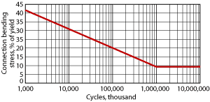
The connection combines the excellent structural features of the wedged thread with the high-pressure gas-sealing reliability of the metal-to-metal seal. The load and attack flanks with negative angles provide a better distribution for the torque stress along the whole thread, which is essential for drilling operations. The stress distribution provides additional sealing besides the metal-to-metal connection seal. The high bending loads together with pipe rotation also generate fatigue loads on the drillstring. Although wedge thread connections provide high torque strength, it is important to get an accurate estimate of the connections’ fatigue life under operating conditions. Connection fatigue life is estimated by determining the cyclic bending stress in the build interval, then determining the number of cycles (revolutions) that can be safely applied to the drillstring from a stress-cycles ( or S-N) curve. The cyclic bending stress may be calculated as follows:
σb = stress created by bending, in psi U = build angle, in °/100 ft D = OD of the pipe body, in in. Et = tension efficiency of the connection, in decimal form
A safety factor is applied to this bending stress value, and the product is converted into a percentage of pipe body yield strength, Fig. 4.
The highest number of cycles for the HD-513 connection in DWL operations was estimated at 290,000. It was considered that a maximum of 763 ft would be drilled in 60 hr, at ROP of 10 ft/hr and 80 rpm until the top El Abra was detected. The real number of cycles reached was 169,782 at 80 rpm at an ROP of 8 ft/hr (266 ft in 35.37 hr). Drillbit selection. Weatherford’s DrillShoe 3 (DS3) was selected; the bit is designed to drill formations ranging from semi-hard to hard (15,000-psi compressive stresses). The bit incorporates a drillable, cyclic pressure piston, which displaces the PDC fins toward the annulus, once total depth is reached, and converts the bit into a cementing shoe. The tool features heat-stable central diamond cutters, PDC cutters at the shoulder, drillable nozzles and carbide protection at the caliper. It may be fully drilled with tricone or PDC bits. Bottomhole assembly. After drilling conventionally to a planned depth of 9,453 ft with a 12¼-in. PDC bit and rotary steerable system (RSS-LWD/MWD-APWD), a simulated DWL trip was made into the borehole with a PDC bit and stabilized drillstring. The borehole was reamed from 5,727 to 9,453 ft, with the following parameters:
The 9 5/8-in. liner assembly was picked up and run to the bottom of the hole. It was made up with the following order:
At a final depth of 9,715 ft, the following parameters were attained:
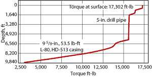
The estimate for maximum torque at the surface using DWL reached 17,302 ft-lb, Fig. 5. During execution to 9,715 ft, the highest value was 19,100 ft-lb; there was a 9% deviation with regard to the prediction.
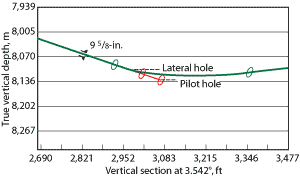
Drilling hydraulics. Technical software hydraulics simulations were performed, and the maximum rate to be applied at the bottom of the hole was estimated at 550 gpm, which generated a work pressure of 1,202 psi. The cleanup velocity for the 5-in. annulus inside the 13 3/8-in. casing had a minimum value of 103 ft/min and a maximum of 235 ft/min at the 12¼-in. x 9 5/8-in. annulus. When drilling was performed to 9,715 ft, a maximum work pressure of 1,250 psi was reached with a rate of 480 gpm. In both cases, seven 14/32-in. nozzles were used. Directional path. The 12¼-in. section was drilled with RSS to 9,453 ft MD, reaching a 75.70° angle. Afterward, DWL was applied to 9,715 ft, with a 75.40° inclination, observing an inclination variation of 0.30°, Fig. 6.
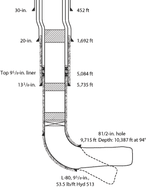
Directionally, the working azimuth varied by 1.56° (352.82°–354.38°). The DWL approach allowed drilling without any risk of inclination angle loss or well direction shift. Geopressures and mud weight. The well was drilled down to El Abra formation with a maximum mud weight of 11 ppg. Then, upon drilling the pilothole and the second lateral borehole, potassium brine of 8.8 ppg was used, according to plan. CARPA-55 OPERATION A 12¼-in. hole was drilled using a PDC bit to 8,639 ft, reaching a 76.35° maximum inclination, and continued tangentially to 9,453 ft MD with a 75° inclination (7,993 ft TVD), Fig. 7. The 9 5/8-in. liner assembly was picked up and run to the bottom of the hole. The total liner length was 4,953 ft. The well was circulated for cleanup purposes, and drilling was performed to 9,715 ft without any problems.
A cemented head was assembled, the 1¾-in. ball was dropped, and pressure was increased to 2,750 psi. Pins were broken and the liner hanger was activated; weight was unloaded; hanger anchoring was checked; the running tool was released and 30,000 lb of weight was applied. After cementing with full returns, the liner running tool was backed off in casing, and circulation was done without any slurry coming to the surface. A 6½-in. PDC bit was assembled and lowered at 1.83°, and a pilothole was drilled to 9,965 ft with a 74.20° inclination. The bit was raised to the 9 5/8-in. shoe, and a lateral borehole was drilled to 10,388 ft TD with a 94° inclination and horizontal displacement of 3,496 ft. A production test yielded 1,437 bopd using 3/8-in. choke and tubing pressure of 610 psi. After the flow tests, the well was shut down awaiting the production export pipeline. CONCLUSIONS Application of DWL in high-angle wells was successful in drilling 266 ft in 46.5 hours to 9,715 ft, with a 75° inclination. This is the first time that Pemex has drilled such an inclination with DWL. The technique reduced problems and related costs in circulation loss zones, saving 40 days and US $5.0 million. The DWL technique does not require any changes in drilling equipment, and the components needed for its application are standard and readily available. Initial problems opening the cementing shoe and liner hanger highlighted the importance of choosing suitable accessories, couplings, hanger and components for DWL to ensure successful operations. It is expected that, with appropriate adaptations performed on the system components, the technique may be reliably applied in similar conditions using different liner diameters.
|
||||||||||||||||||||||||||||||||||||||||||||||||||||||||||||||
- Coiled tubing drilling’s role in the energy transition (March 2024)
- Advancing offshore decarbonization through electrification of FPSOs (March 2024)
- Subsea technology- Corrosion monitoring: From failure to success (February 2024)
- Using data to create new completion efficiencies (February 2024)
- Digital tool kit enhances real-time decision-making to improve drilling efficiency and performance (February 2024)
- E&P outside the U.S. maintains a disciplined pace (February 2024)

