Wellbore chemical inflow profiling at Shell's Cutter AB
Use of chemical paint on tracer material highlights areas of inflow along the wellbore.
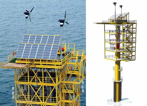
Completion TechnologyWellbore chemical inflow profiling at Shell’s Cutter ABAn industry first lowers cost and reduces HSE exposure.David A. Brown, Sakhalin Energy Investment Co. Shell’s Cutter development is notable for a number of industry firsts, in particular the use of wind and solar technologies in the production of natural gas, Fig. 1. Another industry first is the use of chemical paint on tracer materials that can highlight areas of inflow along the wellbore simply by sampling the hydrocarbon stream at surface for the tracer’s presence. This enables basic downhole flow information to be obtained at a fraction of the cost compared with a PLT.
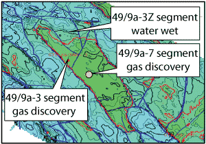
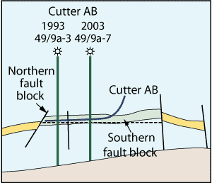
Field background Cutter field is in the southern sector of the North Sea, 75 mi (120 km) from the Norfolk coast. It exports the gas through 175 km of subsea pipelines to Bacton Gas Plant over the Shell-operated Carrack and Clipper platforms. The design of the Cutter field Trident monotower is based on offshore wind turbines. The monotower’s lower construction and operating costs enable the access and recovery of small resource pockets that previously would have been uneconomical. The field’s development, Fig. 2, is based on two wells drilled off the monotower structure. The first well, Cutter AB, is a 3,500-ft horizontal well that connects two fault blocks. There was no production logging planned for the well, and the cost of the operation was deemed too high. At a late planning stage, it was decided to try a new inflow profiling technology.
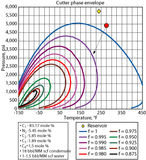
Chemical inflow profiling The concept was developed and is used today by Tracerco and Norske Hydro for horizontal oil wells with sand screen completions. The chemical tracer compounds are painted onto various downhole completion components. When the well is brought onto production, the hydrocarbon stream washes off the tracer material, and the oil is sampled on the surface where inflow areas can be detected. Shell is using this technology for the first time in the industry in the gas well. The largest uncertainty with its use was that a liquid (oil/condensate phase) needs to be present for the tracer material to be stripped off. Since the Cutter AB gas has a condensate-to-gas ratio of 18 bbl/MMcf, engineers estimated that this would be sufficient for the concept to work, Fig. 3.
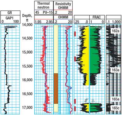
Cutter AB operations A compositional breakdown of the Cutter gas was supplied to Tracerco, who selected four tracers. The tracers were applied to the inside of a 4 ½-in. pre-drilled liner that was used as the reservoir completion. The tracer joints were located across strategic intervals in the open hole, Fig. 4:
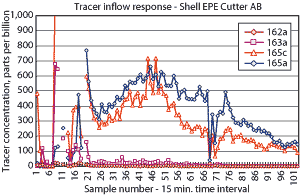
The completion system was run and the well was brought onstream via a well test package. The gas stream was then sampled upstream of the sand filters. Sampling was done at 15-min. intervals, collecting more than 100 samples. This high sample volume was a critical success factor. Results The sample results are shown in Fig. 5. In summary:
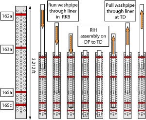
The results seem counterintuitive. Fig. 6 illustrates the running sequence of the pre-drilled liner, and the inner string can explain the results by the amount of wear seen by the liner due to washpipe wear.
Tracer joint 162a (14,384–14,428 ft) had 5,778 ft of washpipe wear and produced the weakest response. Tracer joint 163a (15,130–15,174 ft) had 4,286 ft of washpipe wear, which produced a weak response. Tracer joint 165a (16,848–16,892 ft) had 850 ft of washpipe wear and produced the strongest response. Tracer joint 165c (17,057–17,102 ft) had 432 ft of washpipe wear and gave a strong response. Indications were that all intervals were flowing and that wear can explain the weak upper-zone response. Overall, the trial went well. Highlights include an industry first—chemical tracer technology will work in wet gas. There was a very visible signature and no uncertainty about the results. The high sample rate gave an indicative data set. There was zero impact on the well operation’s critical path value of information. Finally, there was no HSE impact, no intervention, no mechanical risk and zero environmental impact. Future applications Tracer technology is proven in oil wells and there are many future possibilities. The author has had discussions with various operating units about using it to determine if multilaterals legs are flowing, where no information would be possible due to complex completion designs and costs. The technology cuts well costs, reduces HSE exposure and reduces mechanical risk. For multilaterals, especially difficult multilaterals, considerable savings are possible per well. Tracer technology can sample at distant hosts. As a “sleeper” technology, it can be dormant for 6–8 months before production starts. It also enables sampling at the FSO and surface production manifolds from deepwater wells. The technology can be used in conjunction with smart-well technology/ESS, etc., and statistical analysis can be used to determine inflow percentages. There are now a greater number (10+) of tracers available.
|
||||||||||||||||||||||||||||
- Advancing offshore decarbonization through electrification of FPSOs (March 2024)
- What's new in production (February 2024)
- Subsea technology- Corrosion monitoring: From failure to success (February 2024)
- U.S. operators reduce activity as crude prices plunge (February 2024)
- U.S. producing gas wells increase despite low prices (February 2024)
- U.S. oil and natural gas production hits record highs (February 2024)

