Intelligent Well Completions
Closing the loop on intelligent wells
Automation of individual wells leads to field-wide efficiencies.
Walter Going and Adam Anderson, Baker Oil Tools, and Dr. Guy Vachon, Baker Hughes
Intelligent well systems provide options for addressing expected and unforeseen well and reservoir conditions. Increasingly, field operators are realizing the value of using intelligent well systems to remotely monitor the condition of the well and implement real-time or near-real-time control functions. Even greater value can accrue when the subsystems that contribute to the well’s intelligence become more aware of each other and begin to provide well-centric, closed-loop control that improves efficiency and recovery beyond what is presently realized from remote monitoring and control alone.
BENEFITS
Much of the current focus on smart fields revolves around a reservoir-centric, or slow loop, as shown in Fig. 1.
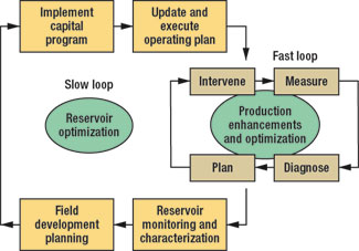 |
Fig. 1. The present smart field focus revolves around a slow loop, centered on the reservoir. The faster, well-centric loop automates calculation-intensive tasks to maximize efficiencies and optimize recovery, while reducing risk and costs.
|
|
Proving the ability of a closed-loop system to maximize efficiencies and optimize recovery while reducing risk and costs is much easier at the individual well level than for an entire reservoir. The faster, well-centric loop, Fig. 1, can be accomplished by automating key tasks that are calculation-intensive in current operator workflows. For this article, automation is defined as the continuous and automatic transfer of data between systems, including the generation of alarms based on user-defined rules. An intelligent well system is a completion system that provides the ability to remotely monitor and control production or injection in many zones in a single well. Intelligent well equipment is any device that allows adapting the well to its best possible operating condition without an intervention.
The example in this article is a dual-zone electrical submersible pump (ESP) producer that uses a multi-position adjustable choke to control production from each zone and a chemical injection mandrel for treatment as needed, Fig. 2.
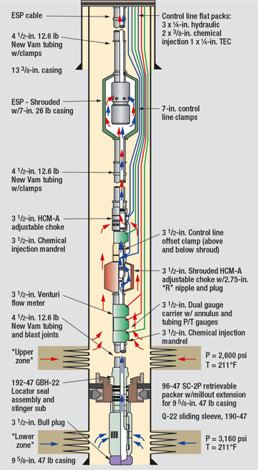 |
Fig. 2. This dual-zone electrical submersible pump producer uses a multi-position adjustable choke to control production from each zone and a chemical injection mandrel for treatment.
|
|
This well offers many intelligent data and control possibilities. Instrumentation is provided that monitors pressure and temperature in both upper and lower zones as well as flow rate and water cut from the lower zone. Combined with a three-phase flow meter at surface, this system can allocate three-phase production to both the upper and lower zones. A remotely operated, downhole choke regulates drawdown pressure from each zone to minimize cross-flow and/or optimize production rates. The ESP is also equipped with a downhole monitoring package that measures and records intake pressure, case temperature and vibration data.
Depending upon the degree of vendor integration chosen for the project, the array of independent intelligent interfaces deployed at surface may include surface temperature and pressure readouts, surface flow measurements, a readout and data acquisition system for downhole zonal gauges, a hydraulic power unit (HPU) and associated controller for downhole adjustable chokes, a chemical injection pump and associated controller, variable speed drive for the ESP, and a monitoring system for the ESP gauge package.
Typically, the incremental expense of an intelligent well versus a conventional completion is justified by using modeling to illustrate the potential benefits. These benefits may include increased ultimate recovery, accelerated production, cost reduction by having one well do the work of two, or cost and risk reduction by avoiding costly intervention. Similarly, if placing adjustable downhole chokes in an intelligent well adds value, it follows that the optimum performance of the well will require changing the choke settings during the well life. The well-centric closed loop system described in this article can apply the same nodal analysis process that justified intelligent well economics initially to guide the well’s operation.
The primary functional components of an intelligent production system with closed-loop control are well monitoring, well and reservoir modeling, decision making, and control and optimization. Closing the well loop, traditionally, has involved a human who monitors the well, observes how actual production compares to the original analysis and issues commands for the intelligent well to be reconfigured.
Closing the loop with automated systems can add value in several ways. Resource, equipment and workflow efficiencies can be maximized. Accelerating well recovery and prolonging a well’s productive life by adjusting a few simple parameters can positively impact the entire reservoir. Controlling production and accurately forecasting production flows can help operators meet government regulations focused on field optimization. Combining systems and reducing human intervention at the well site reduces the exposure to commuting hazards and leverages the improved efficiencies of experts working in their normal environments, while enhancing the ability to alert operators when well maintenance is needed. Faster response and decision-making based on automatic alerts on certain pre-defined conditions can reduce costs and improve profits.
Adding automation facilitates human intervention by retaining the well model and changing the monitoring activity from polling to interrupt-driven to help maximize resource, equipment and workflow efficiencies, and improve well recovery, safety and reliability. Eventually, automated systems will be able to advise when wells deviate from their expected behavior in ways that prompt diagnosis of emerging, unexpected problems early enough to avoid them.
OPTIONS
During an intelligent well’s early life, the surface subsystems that interface with the downhole equipment commonly operate as standalone entities that are periodically monitored and manually logged. Eventually, collective monitoring and data acquisition may consolidate the available data into a single-source repository and enable control from a remote location via a Supervisory Control and Data Acquisition (SCADA) system. These steps increase the amount of available data for making control decisions but do not change the means by which the data are analyzed. Because high volumes of raw data are unwieldy until analyzed, monitoring unprocessed data does not in itself add significant value to an intelligent well.
The emphasis on well-centric closed-loop systems going forward is to provide systems that use available data to enhance decision-making to improve efficiency and recovery above and beyond what is currently realized from intelligent well control and remote monitoring alone.
The slow-loop optimization process requires processing wellsite data with analysis tools that typically are reserved for operation at central locations. Using these same tools offers at least three options to close the well-centric control loop by automating data processing and output commands to modify the producing configuration of the well.
Option 1 involves sending an alarm to an operator detailing the recommendation for external review and manual control execution. This option most closely follows the traditional path of having a person execute the direct control and presumably observe the system’s response. Preprogrammed analysis is delivered to the decision maker. The efficiency gain comes from automating the analysis, which limits the decision-maker’s action to validating the conclusion and acting on the result.
Option 2 calls for performing the recommended control function in response to operator confirmation. This option increases efficiency when executing the change in control is complex and the system is programmed to deal with the complexity. An example where this option would be advantageous is changing the operating point for a downhole choke. Adjusting downhole chokes frequently requires executing a sequence of hydraulic outputs over an extended period of time. Using Option 2, the operator would receive a system message proposing a change to the downhole choke setting. The change would be implemented only after receiving a confirmation from the person monitoring the process.
In Option 3, the control function is performed, and the operator is notified of the action taken. The analysis and control capabilities required to execute this option exist in current intelligent well systems. However, because it removes human oversight from the control loop, it requires considerable confidence in the accuracy and stability of the entire process. It also assumes that the software accommodates the health, safety and environmental requirements and the side effects of any action that affects well production. The confidence to employ Option 3 will evolve in part from successes obtained with systems that are initially deployed using Options 1 and 2. Regardless of the control operations and feedback opportunities, some intelligent wells are more obvious candidates for early application of closed-loop control than others.
AUTOMATED CONTROL OF SIMPLE FUNCTIONS
Completing the well illustrated in Fig. 2 with interconnected surface support systems that consolidate all available data and control functions into a SCADA system offers many opportunities for automating functions and processes that reoccur throughout the life of the completion, Fig. 3.
 |
Fig. 3. Interconnected surface support systems consolidate all available well data and control functions into a SCADA system.
|
|
For example, the downhole adjustable chokes will require many setting changes over the life of the well. After being trained and given written instruction on the manufacturer’s hydraulic logic, well technicians can use a manually controlled HPU to adjust the chokes. Conversely, the HPU can be constructed for automation such that all valving can be switched by commands from a microprocessor. Replacing the manual HPU with an automation-friendly version yields numerous options for control distribution.
The first function for the automated HPU is providing the hydraulic outputs to adjust the choke settings. The system should also maintain a record of the current choke setting. The simplest method is to input the choke setting when the system is commissioned, then update the position with each hydraulic output cycle, which would change the choke setting. A preferable solution is for the control system to monitor a feedback parameter which can be fed into logic to confirm that the intended change has occurred downhole.
For an adjustable choke such as the Baker Oil Tools HCM-A, which is operated using a balanced hydraulic piston, hydraulic fluid volume returning to the HPU provides feedback. When the choke position is changed by applying hydraulic pressure at surface, the fluid volume delivered from surface will be the sum of the volume consumed within the receiving chamber of the downhole choke plus the volume required to pressure the control line. The volume returned to the HPU via the opposite control line will be exactly the fluid displacement volume from the opposite fluid chamber in the choke.
Without automated HPU feedback to confirm that the choke adjustment is complete, the operator can survey well performance indicators such as downhole pressures and flow rates for confirmation. The limitations of using only well performance indicators is that the parameter values corresponding to the choke position must first be learned from early well performance and adjusted as they change over time.
Programming logic to adjust the downhole choke ensures positioning reliability and operational efficiency. For example, the HCM-A adjustable choke has six unique choke settings in addition to fully open and fully closed, or 14 total identifiable positions including repetition of fully open following each choked position and following the fully closed position. The 14 positions are accessed in a repetitive sequence in accordance with the customer’s specification for the specific choke settings needed. The most convenient choke adjustment sequence requires two hydraulic outputs, one to move the choke to fully open and the second to move the choke to the next setting in the sequence. The most inconvenient adjustment sequence occurs when the desired new setting is the previous setting. This sequence requires up to 12 hydraulic outputs. The value of automating the process becomes obvious when considering the time required to apply and bleed pressure 12 times. Depending on the depth of the downhole chokes and type of hydraulic fluid employed, it is not uncommon for 12 hydraulic shifts to consume more than two hours. By programming the control system to execute the shift sequence automatically, the well technician is freed to attend to other tasks. Additional efficiencies are gained if the process can be commanded and observed remotely.
Fig. 4 illustrates a simplified logic flowchart to manage either a single position change for a downhole choke or a change through several positions. In this example, agreement between the volume of hydraulic fluid returned to the HPU and the choke displacement volume confirms that the shift is complete. For other systems the feedback parameter is easily revised to handle variations on the tool functional characteristics. Variations of this logic have been used in eight surface control units. The additional expense for the control system is offset by the reduction in operator training needed to properly control the downhole chokes.
 |
Fig. 4. This simplified logic flowchart manages either a single position change for a downhole choke or a change through several positions.
|
|
Using automation to shift downhole chokes and measure the volume of returned hydraulic fluid can close the loop within a subsystem for which a vendor is wholly responsible for equipment supply, including the sleeves and the surface control system. The same functionality could be programmed into the operator’s SCADA system. However, it is more efficient to place the logic and control commands on the vendor’s system because the programming effort to create the program logic is reusable for many applications. Because the entire logic implementation is handled by the downhole vendor, the operator minimizes the quantity and complexity of interface issues between the SCADA provider and the downhole equipment vendor. Low-level control commands such as, “Apply hydraulic output ‘A’,” “Measure return fluid volume,” and “Compare return volume to expected value” reside on the downhole vendor’s controller. Only higher-level commands such as, “Set Upper Sleeve to Choke Position 7” are needed from the SCADA system when it is linked to the downhole controller.
In this example, implementing control logic at the lowest level is beneficial. The approach is very compatible with a SCADA central control in that the command to drive the shift sequence can still come from the SCADA system, which can also monitor the progress of the sequence being executed by the HPU.
SCADA CONTROL FOR COMPLEX FUNCTIONS
An ESP-lifted well will need to be shut in from time to time. Given sufficient duration, each shutdown and startup provides an opportunity to acquire new buildup and drawdown data that can be processed to update the original reservoir parameters and modify the production parameters if warranted, Fig. 5. Assuming that the acquisition rate during periods of normal production is too infrequent to obtain optimal build-up data, the first action during shut-in will be to increase the data recording rate. At least one downhole choke must be closed after the ESP is shut down to isolate the two zones. Closing the second choke will further enhance the value of the data by eliminating wellbore storage effect.
 |
Fig. 5. In this data acquisition sequence, each shutdown and startup is an opportunity to acquire new buildup and drawdown data that can be used to modify production parameters.
|
|
When standalone interfaces control the well, capitalizing on the opportunity to obtain build-up data requires the production technician or technicians to manually execute the process. Shortening the time required to isolate the zones after production ceases will improve data quality. Thus, the objective is to reset the data rate for the surface and downhole gauges, shut down the pump, close the production wing valve and close the downhole choke in the shortest amount of time. Using a closed-loop control system, where the data acquisition components, ESP and downhole choke control are integrated, limits the technician’s manual action to initiating the shut-down sequence and closing the (manual) wing valve. The remaining activities can be driven by the SCADA system. If the wing valve is automated, the entire process can be driven by the SCADA system with single command.
This level of integration is being considered for smart fields, whose aim is to tie all of the monitors and controls for a well into an addressable system and link entire fields to a central command and analysis system. Whether as a step to linking to a field-wide system or as the complete solution, a well-centric loop is relatively simple to construct when the commitment has already been made to provide the individual components.
In the example in Fig. 4, the SCADA system communicates with the ESP variable speed drive controller and the controller for the downhole adjustable chokes. The downhole gauges communicate with the choke controller, which also serves as a backup historian for both the choke position history and archives the gauge data. The SCADA system uses MODBUS communication protocol. The downhole choke controller is programmed for autonomous control of the hydraulic outputs required to shift the chokes and maintain the record of choke position. Placing all of the logic in the choke controller minimizes commands sent to the controller by the SCADA system and eliminates the need to replicate the choke vendor’s logic in the SCADA software. This architecture also provides the means to control the chokes locally and monitor the downhole gauges during any period of unavailability of the SCADA system. Similarly, placing the data logging function for the downhole gauges on the controller avoids the limitation for data logging rate to the SCADA system.
Each new pressure buildup data set initially exists only at the well site. Yet, the data adds value only after it is processed to obtain current reservoir properties. Although it may be technically possible to place reservoir analysis tools on the SCADA system or another local processor, it is much more efficient to perform the analysis using the processors, software licenses and other analysis resources at a central location. Therefore, the next step in closing the loop is to implement a communication link between the data acquired at the well site and the central location analysis system. Selecting the best means to transfer the data requires considering whether data communication will occur across a secure internal network or via less reliable links. Database replication may be the best solution across a secure and reliable network. For a less robust communication link, tagged data such as the PRODML protocol may be more reliable.
Having the basic communication infrastructure is still only one piece of obtaining value from the acquired data. The remainder of the loop must also be controlled. Using the manual method described in Option 1, the buildup dataset would reside in the controller’s memory to retrieve and analyze. The engineer would initiate analysis only after becoming aware of the existence of the data, either from a message generated by the SCADA system or by scanning for new data. In this scenario, the preference would be for the SCADA system to output a notice to the engineer that new data was available.
Option 2 affords more aggressive implementation, including exporting the buildup data to a computer for processing. The processed data would yield updated reservoir parameters such as skin and PI, which could then be used to rerun the well nodal analysis. Outputs from these analyses would include an optimized plan for the choke settings, which would be contained in a computer-generated report of new recommended parameters that would be sent to operations and the reservoir engineer for review and implementation.
EXPANDING AUTOMATION
Once enough success and incremental benefits can be documented using the semi-automated control inherent in Option 2, implementing the fully automated control of Option 3 will become practical to automatically pre-program new choke settings to re-start production. Automating the well shut-in process is an example of a readily understood and easily programmed function. The communication and control technology exists to extend automated feedback processes considerably beyond the limits of fixed operation sequencing.
Typically, an intelligent well is designed to accommodate the circumstances it is expected to encounter, based on simulated well performance. The closed-loop examples in this article address situations where the well is performing within the parameters expected at the time it was designed. The control algorithm can almost be pre-designed to suggest some particular action when a well circumstance such as formation pressure, PI, etc., reaches some predetermined level.
What happens when the well does not behave as expected? This question reveals another rich source of potential for closed-loop control. An automated system with memory of the expected well performance can differentiate normal ageing from pathological behavior and then flag a well for attention. Ultimately, only this type of anomaly will warrant human intervention. 
REFERENCES
Going, W.S., Thigpen, B.L., Chok, P.M., Anderson, A.B., Vachon, G.P., “Intelligent Well Technology: Are we ready for closed loop control?,” SPE 99834, presented at the 2006 SPE Intelligent Energy Conference and Exhibition in Amsterdam, The Netherlands, April 11 – 13, 2006.
Going, W.S., Anderson, A.B., Vachon, G.P., “Intelligent Well Technology – the evolution to closed-loop control,” OTC 17796, presented at the 2006 Offshore Technology Conference in Houston, Texas, May 1 – 4, 2006.
McCelvey, M,, Puckett, R., Solano, M., and Krejci, M., “Intelligent well system with hydraulic adjustable chokes and permanent monitoring improves conventional ESP completion for an operator in Ecuador,” SPE 88506, presented at the SPE Asia Pacific Oil and Gas Conference and Exhibition in Perth, Australia, October 18 – 20, 2004.
Botto, G., Giuliani, C., Maggioni, B., Rubbo, R., “Innovative remote controlled completion for Aquila Deepwater Challenge,” SPE 36948 at the European Petroleum Conference in Milan, Italy, October 22 – 24, 1996.
|
THE AUTHORS
|
 |
Walter Going is senior engineering manger for the Intelligent Well Systems group at Baker Oil Tools. His is responsible for design and support of control systems for Intelligent Wells. Prior to joining Baker in 1997, he worked for Hughes Tool from 1970 to 1979, for Camco from 1979-1993 and for Sonsub from 1993-1997. Going received his BSME from the University of Texas-Austin.
|
|
 |
Adam Anderson is product line manger for Intelligent Well Systems in Saudi Arabia for Baker Oil Tools. Prior to this position, he was the global product line manager for Intelligent Well Systems, Flow Control and Gas Lift based in Houston, Texas. Prior to joining Baker Oil Tools, He worked in a variety of operations and sales roles for PES/ WellDynamics. Anderson earned a BS in Petroleum Engineering from The Colorado School of Mines.
|
|
 |
Dr. Guy Vachon is director of Optimization Solutions for Production Quest at Baker Hughes. He worked for Schlumberger from 1984 to 1999 as an engineer and manager. From 1999 to 2003 he managed Industrial Automation and Technical Data Management Software at National Instruments. In 2003, Vachon joined Baker Oil Tools and in 2006 moved to Baker Hughes’ Production Optimization Business Unit. Vachon earned his BS, MS, and PhD in EECS from MIT and MBA from University of Texas-Austin.
|
|
|

