Casing While Drilling
Casing while drilling "smear effect" improves wellbore stability
South Texas Lobo trend NPT overcome using casing while drilling technique.
Kyle Fontenot and Robert D. Strickler, ConocoPhillips; and Pete Molina, Baroid product service
line, Halliburton
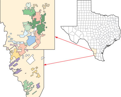
ConocoPhillips has had a sustained, multi-rig development program in the Lobo trend since 1997 having drilled more than
120 wells and 1.6 million ft of hole in Webb and Zapata Counties, Texas, Fig. 1. The field development program required drilling more than 900 wells over a six-year
period. By 2001, achieving further drilling efficiencies using conventional methods was proving difficult.
 |
|
Fig. 1. The Lobo field development program in south Texas required drilling more than 900
wells over a six-year period. |
|
Non-Productive Time (NPT) on these wells had been reduced to less than 10% of overall drilling time. However, drilling
efficiencies had to be further improved to extend the development potential.
Well construction costs were impacted by three key issues: lost circulation, stuck pipe, and flat time at casing points.
During 2000 and 2001, loss of circulation and stuck pipe accounted for 75% of the trouble time in the highly-faulted Lobo field. Well control situations and problems
setting 7-in. intermediate casing also accounted for a significant percentage of NPT.
The decision was made to evaluate drilling with casing to potentially reduce or eliminate the downhole problems, and
therefore make drilling more economic. As the term implies, Casing While Drilling (CWD) allows the well to be drilled and cased at the same time and is designed to
eliminate the need to trip the drillstring out of the hole.1
A successful five-well CWD pilot program led to widespread application of the technology by ConocoPhillips in south Texas.
Other operators are also employing CWD technology in the area.
TROUBLE TIME
Based on analysis of Lobo wells drilled conventionally between 2000 and 2002, 38% of trouble time was related to lost
circulation, while stuck pipe accounted for 34 – 37% of trouble time.2 Given this potential for lost circulation, differential sticking, and well control
situations, removing the need to pull out of the hole to lay down drill pipe and run casing provided an immediate advantage. Nonetheless, at the outset of the CWD pilot
program, there was concern that a restricted annulus and higher frictional pressure losses would elevate the Effective Circulating Density (ECD) and exacerbate the
potential for lost circulation. This concern was addressed by drilling with a lower mud weight and using the ECD in a beneficial way to achieve the required bottomhole
pressure to maintain wellbore stability. This positive application led to a new perception of ECD as “dynamic mud weight.”
By the end of Phase Two of the CWD program (22 wells drilled), lost circulation accounted for only 0.4% of trouble time, a
radical improvement in wellbore stability. Although mechanical problems have made it necessary to trip the casing out of the hole on 9 of first 72 CWD wells, stuck pipe
occurred in only three incidents. The pipe was freed on two wells. In the third case, where stuck pipe occurred after a kick near the intermediate casing point, the
casing was cemented in place slightly above the original casing point. No further problems were encountered and the well was successfully drilled to total depth.
SMEAR EFFECT
The seeming paradox of achieving significantly reduced losses despite running higher than normal ECDs has been attributed
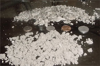
in part to the smear effect. Results of the particle size distribution performed on cuttings from the Water-Based Fluid section of a casing-drilled well indicate that
cuttings generated with CWD are unusually small, while those returned to surface with conventional drilling are much larger, Fig. 2. On the sample from the CWD operation,
the mean particle size was 2.626 microns, with 90% of the particles measuring less than 6 microns in diameter, Fig. 3.
 |
|
Fig. 2. Compared to conventional drilling, cuttings generated with CWD are unusually
small. |
|
 |
|
Fig. 3. On a CWD cuttings sample from 7,700 ft, the mean particle size is 2.626 microns,
with most less than 6 microns in diameter. |
|
Because of the CWD side-load forces, the cuttings are pulverized in the narrow annulus and as they travel toward surface.
The particles apparently become embedded in the wellbore wall and help form a natural seal that is much more impermeable than a wall cake produced by mud additives alone.
This smear effect is most clearly exhibited in the intermediate interval, where the annular restriction is greatest and in almost continuous contact with the
rotating pipe.
Intermediate interval. A Low-Solids, Non-Dispersed (LSND) system is used to drill the 7-in. x 8-7/8-in.
intermediate section. This system is designed to emulate water, achieve maximum shear thinning, and allow the formations drilled to “make mud.”
About 50% less bentonite is used in CWD operations than is used on equivalent conventionally drilled wells. The bentonite
is augmented with a partially hydrolyzed polyacrylamide/ polyacrylate (PHPA) polymer. Standard polyanionic cellulose is used for fluid loss control near the end of the
interval. Densities typically range from 9.0 to 10.5 lb/gal, but heavier weights are sometimes needed to control connection and background gas.
Maintaining low gravity solids at a value of 6% or less by volume is desirable. The target methylene blue test value is 15
or less lb/bbl equivalent. No shale control additives are used. The cuttings returning to surface resemble silt and are typically removed with 250-mesh shaker screens, as
compared to 175- to 210-mesh screens used on conventional rigs in the area, Fig. 4.
 |
|
Fig. 4. The CWD cuttings returning to surface resemble silt and are typically removed
with 250-mesh shaker screens of cuttings, CWD cuttings (bottom) and conventional drilling operations (top). |
|
Production interval. A standard diesel-based system is used to drill the production interval. The diesel-based
fluid can provide the lubricity and temperature stability required in the deeper sections of Lobo field wells. For drilling depleted zones, pretreatment using sized
calcium carbonate is standard procedure on both CWD and conventional rigs. When losses occur, a sized calcium carbonate sweep is pumped. Fibrous and asphalt materials may
be added to the sweeps to aid with bridging in depleted zones.
The production interval is drilled with 11.6-lb/ft and 13.5-lb/ft, 4-1/2-in. casing with a 6-1/4-in. bit, so that
operations in this interval most closely resemble drilling on conventional rigs. Hydraulics at the bit are somewhat better with CWD because less internal friction losses
occur with 4-1/2-in. casing. Pump rates average 225 gal/min, as compared to 200 – 225 gal/min on conventional rigs.
FLOW REGIME
The flowrates used with CWD are typically lower than those used with conventional drillpipe drilling. For example, with
conventional drilling, the 8-3/4-in. intermediate interval is drilled with 450 to 500 gal/min, compared with about 300 gal/min on a CWD operation. The annular velocities
in both cases are similar, but significant differences in ECD occur, Tables 1a-b.
| TABLE 1A. Typical CWD hydraulics per interval |
 |
|
| TABLE 1B. Typical conventional drilling
hydraulics per interval |
 |
|
Pump pressures are lower with CWD because of the large Internal Diameter of the casing. While the surface and intermediate
sections are drilled, the mud pumps on CWD rigs can operate with less horsepower, because they are not required to move fluid down a drillstring with a small ID. The
hydraulic horsepower delivered at the bit is high compared to conventional drilling conditions and the hydraulics should be monitored closely to help prevent a “pump-off”
phenomenon at the bit face. Conditions while drilling the production interval become more similar where 4-in. drillpipe is used on conventional rigs and 4-1/2-in. casing
is used on the CWD operations.
ECD. Concerns about developing high ECDs in a restricted annulus were addressed in early slimhole drilling
studies, where the emphasis was on avoiding hydraulic parameters or rheological properties that might elevate the ECD beyond the fracture gradient.3,4 In
support of this, the use of low solids or solids free fluids has been advocated, accompanied with the caution that fluid design will be greatly constrained by the
increased risks imposed in the slim annulus.
However, consistent results achieved with CWD in the Lobo field indicate that the ECD works positively rather than
negatively for wellbore pressure management and minimizing losses. For CWD purposes, the surface density is generally 0.5 to 1.0 lb/gal lighter than mud weights used on
conventional rigs and is adjusted to provide the desired ECD.
CWD allows the operator to leverage the benefits of the smear effect from PSD, annular sizes, and available pump rates to
achieve a broad range of dynamic mud weights, Fig. 5.
 |
|
Fig. 5. CWD allows the operator to leverage smear effect benefits, annular sizes, and
pump rates to achieve a broad range of dynamic mud weights. |
|
If lost circulation does occur, drilling usually continues with partial returns until the smear effect heals the hole
and/or the casing point is reached. At this point, a sufficient volume of heavier mud is displaced into the well to help ensure the well does not flow during preparations
for cementing.
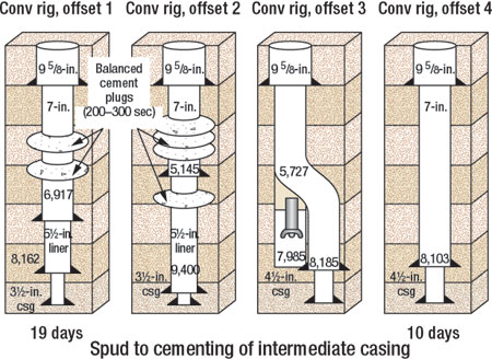
DRILLING IN SEVERE LOSS AREA
The smear effect theory was put to the test after three conventionally drilled wells in the same area of the Lobo field
encountered severe loss of circulation, Fig. 6. In two wells, multiple cement plugs were required to stop the losses. The planned intermediate casing point (± 8,000
ft) could not be reached on either well, and 7-in. casing was set at 6,917 ft and 5,145 ft, respectively. In both cases, a 5-1/2-in. liner was required and the remainder
of the well was drilled with a 4-3/4-in. bit.
 |
|
Fig. 6. The smear effect theory was put to the test after three conventionally drilled
wells in the same Lobo field area had severe loss of circulation. |
|
After reaching intermediate casing point on the third well, the BHA became stuck during a short trip to condition the
well. Lost circulation was encountered while drilling this interval. The fish could not be recovered because of continued circulation loss. The well was kicked-off at
5,272 ft and drilled to 8,185 ft, where the 7-in. casing was set successfully. The well was drilled to TD with 4-in. drill pipe using a 6-1/4-in. bit.
The CWD system was used to drill the next well at this location. Although the mud weight reached 10.5 lb/gal (as compared
with 8.7 lb/gal on the offsets), the well experienced no significant circulation loss and reached the intermediate casing point without incident. Where the first
conventionally drilled well had taken 19 days to reach liner depth at 8,163 ft, the CWD well reached the planned 7-in. casing point at 8,103 ft in 10 days.
Shortly afterward, another conventional offset well was being drilled, when complete loss of circulation occurred at 4,206
ft. After several unsuccessful attempts to cure the loss, the well was plugged and the rig released.
A CWD rig was moved onto location and drilling recommenced. While drilling the lowest cement plug with the LSND
water-based system, the well developed a loss rate of 60 – 200 bbl/hr, but the rate diminished to 20 bbl/hr by the time the bit began drilling new formation. As
drilling continued to the intermediate casing point at 8,143 ft, the loss rate averaged 5 to 10 bbl/hr. In other words, the well went from zero returns to 75% returns in
500 ft and 24 hr.
The 7-in. casing was set and cemented without incident. The trouble cost on the well before its temporary abandonment was
$184,000. The reentry operation had a total trouble cost of only $7,000.
CONCLUSIONS
The hydraulic forces in the restricted annulus encountered during CWD operations create a smear effect on the wellbore
wall that helps minimize losses. Pulverized cuttings appear to adhere to the wellbore wall readily, helping seal pore spaces across loss zones.
While drilling the 7-in. casing interval, where annular restriction is greatest, using a fit-for-purpose, low-solids,
non-dispersed water-based fluid provided the best results in minimizing losses. Due to significantly reduced losses achieved with CWD and the smear effect, the operator
uses this technology on wells that would not be conventionally drilled due to wellbore instability and/or the need for a liner.
Managing a successful CWD operation requires experience and perspective. Many important aspects of conventional drillpipe
thinking do not apply to CWD, and significant adaptation is required to realign or replace conventional processes and practices. All well planning and well construction
personnel should be formally prepared to account for the differences in the two technologies. 
ACKNOWLEDGEMENTS
The authors thank ConocoPhillips and Halliburton for their support and permission to publish this paper.
REFERENCES
1 Tessari, R. et al., “Drilling with casing promises major benefits,”
Oil & Gas Journal. Vol. 97, No. 20, 1999.
2 Fontenot, K., et al., “Casing drilling activity expands in South Texas,” SPE/IADC 79862
presented at the 2003 SPE/IADC Drilling Conference, Amsterdam, The Netherlands, February 19 – 21, 2003.
3 Delwiche, R., et al., “Slimhole drilling hydraulics,” SPE 24596 presented at the 1992 SPE Annual
Technical Conference and Exhibition, Washington, D.C., October 4 – 7, 2002.
4 Cartalos, U. and D. Dupuis, “An analysis accounting for the combined effect of drillstring rotation
and eccentricity on pressure losses in slimhole drilling,” SPE/IADC 25769 presented at the 1993 SPE/IADC Drilling Conference, Amsterdam, The Netherlands, February
23 – 25, 1993.
|
THE AUTHORS |
 |
Kyle R. Fontenot, ConocoPhillips/ Petrozuata. Kyle’s 20 years of experience includes tenours with BP and
ConocoPhillips where he established a broad drilling background ranging from deepwater to onshore and conventional to casing drilling, in both domestic and
international locations. Kyle earned both a BS and a MS in petroleum engineering from LSU. Currently Kyle is assigned to ConocoPhillips’ heavy oil project in
Venezuela, Petrozuata, where he fills the role of operations manager, overseeing the drilling, completion, and workover operations, as well as production engineering
of multi-lateral wells. |
|
 |
Robert D. (Bob) Strickler joined Conoco in 1988 and has 28 years experience planning, supervising and
managing production and drilling operations in offshore, shallow water and land areas, in domestic & international locations. He is current staff drilling
engineer for the South Texas Business Unit, where he is involved in planning and operations for ConocoPhillips casing drilling program. Strickler earned a degree in
petroleum technology in 1978. |
|
 |
Pete Molina is the technical manager for Baroid Fluid Services in south Texas. He has 26 years experience in
drilling fluids with Baroid, including offshore and land operations in the US and Mexico. Molina has been involved in drilling fluid design and implementation in
casing-while-drilling operations since 2001. |
|
|

