HP/HT Drilling
Planning and executing a drilling fluids strategy for a world-record well
A synthetic compliant drilling fluid overcame temperature and pressure effects to drill the well to 26,695 ft.
J. Dieffenbaugher and R. Dupre, Chevron; and G. Authement, G. Mullen, Y. Gonzalez, Baker Hughes Drilling Fluids
Wells can now safely and successfully be drilled in water depths greater than 10,000 ft. The learning curve on these wells has allowed new records to be established at a rapid pace.
Due to the presence of young sediments, many of these wells possess an extremely narrow margin between the pore pressure and the reservoir’s fracture pressure. Because of this, the deeper the operator can push the initial casing string, the greater the likelihood of drilling success.
A riserless drilling technique, known as Dynamic Kill Drilling (DKD), has proven instrumental in pushing casing depths in deepwater and ultra-deepwater environments.1 This technique played an important role in the success of this challenging deepwater project, as the initial upper section was extended to obtain required Leak-Off Tests (LOT) at the 22-in. and 17-7/8-in. casing shoes.
The unmatched combination of technical performance and environmental compliance synthetic-based drilling fluids has made the fluids of choice for deepwater drilling. Based on an overall analysis of this project, the operator selected a proprietary, synthetic, compliant drilling fluid for the drilling of the well from the 18-in. x 22-in. section to TD. This decision was driven by the presence of highly reactive shales in the deepwater formations and the system’s prior performance in offset wells.
In deepwater the main consideration is the effect of temperature and pressure on the fluid system. As the water depth increases, temperature decreases and pressures rise. Typical GOM seabed temperatures are below 40°F at depths greater than 4,000 ft.
This cooling, combined with increased pressure, impacts the drilling fluid design. Due to the chemical composition of GOM-compliant, synthetic-base fluids, cooling will increase a base fluid’s viscosity, resulting in an increase in the overall drilling fluid viscosity. Because of this, particular importance must be paid to the fluid’s viscosity profile to minimize potential problems, such as formation fracturing, which can result in costly lost circulation and nonproductive time. A proper viscosity is also critical to ensure that adequate hole cleaning is maintained throughout the wellbore.
DRILLING FLUID PLAN
Figure 1 shows the initial well plan and some key data. For planning purposes, the well was divided between the riserless, intermediate and bottom sections, where the compliant synthetic-based fluid was applied.
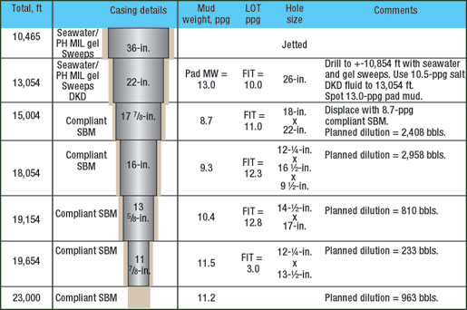 |
Fig. 1. The well plan was divided into riserless, intermediate and bottom sections, where the compliant synthetic-based fluid was applied.
|
|
The stability of shale formations and cuttings has typically served as a performance reference point for GOM-compliant, synthetic drilling fluids. However, particular attention should also be paid to downhole viscosities and effective circulating density (ECD) management, hole cleaning and lost circulation avoidance.
Table 1 is an example list of fluid formulations and properties, as well as the viscosity profiles under various pressure/ temperature conditions for synthetic-based mud at 13,080-ft to 15,004-ft MD. Of particular importance is to have a shear thinning fluid that provides low viscosity at the highest shear rates, while offering high viscosity under the lowest shear rates to minimize the effect on ECD. In addition, the young formations encountered will require the internal phase brine activity (aw) ~ 0.765 to ~ 0.686 or (24% to 28% wt/wt) calcium chloride, to maintain borehole stability – particularly during any unplanned, extended periods of openhole exposure. This level of water activity has successfully drilled young GOM formations during the past decade.
 |
| Table 1 |
|
Synthetic fluid properties, concentrations and viscosity profile for the intermediate interval (13,080–15,004 ft, MD)
Click image for enlarged view |
|
|
The predominant synthetic fluids used in the GOM today are based on neat internal olefins. These are typically of a C16/C18 blend, or an internal olefin blended with an ester. These fluids’ kinematic viscosities are similar at temperatures above 70°F but tend to differ as temperatures decrease. While the kinematic viscosity contributes to the final fluid viscosity, other influential factors include emulsion with brine and, more significantly, the type of viscosifier used. Several joint industry projects concluded that high-quality organophilic clay is the most efficient viscosifier for synthetic drilling fluids for temperature fluctuations and suspension properties. For this reason, rheology modifiers were not recommended on this well.
HYDRAULICS
Optimum viscosity profiles were studied. There are three critical parameters – compressibility, viscosity and hole cleaning – that affect pressure-related issues, such as ECD management and swab and surge in deepwater drilling applications. The fluid’s viscosity profile in the wellbore must be as thin as possible (from an ECD standpoint) while remaining sufficiently viscous to transport cuttings in a dynamic situation, and to suspend weight material and cuttings under static conditions.
Due to this well’s temperature fluctuations, it was critical that the drilling fluids’ viscosity profile minimizes ECD while providing effective hole cleaning. Therefore, the fluids were designed to have lower viscosity in the highest shear rate region and higher viscosity in the lowest shear rate region.
With synthetic drilling fluids, increased pressures result in increased viscosity, while higher temperatures usually result in lower viscosity. Therefore, the ability to accurately simulate downhole hydraulics depends on a fluid’s viscosity profile under temperature and pressure conditions. Field muds were tested extensively for viscosity dependence on a viscometer that simulating downhole pressure and temperature conditions.
A synthetic-based fluid’s compressibility depends on temperature and pressure, as well. Another characteristic of these fluids, is the effect of Pressure, Volume and Temperature (PVT) on mud density. It is critical that the hydraulic modeling be capable of compensating for PVT data of the various drilling fluid components. Several fluid compositions were evaluated before achieving the desired final fluid composition and viscosity profile.
In addition, hole-cleaning effectiveness depends on fluid properties to some degree. However, parameters that affect cuttings removal, such as ROP, cuttings characteristics (density, size) and overall drilling practices, remain independent of the fluid company’s control.
For the hydraulic and hole-cleaning analysis, the service company’s proprietary hydraulics modeling software was used. It offered a compositional model for whole-mud density calculations, rm(p, T). The software allowed the user to either use the well’s calculated temperature model or input a user-defined temperature profile. In addition, the software drew upon the Herschel Buckley model for characterizing fluids and calculating pressure losses.
Finally, the software offered fluid modelers various scenarios of downhole pressure and temperature conditions. These included:
- Hole cleaning
- Split-flow pressure losses
- Hole opening and underreaming
- Casing milling
- Swab and surge under downhole conditions
- Total hydraulic system pressure losses, including ECD, Equivalent Static Density (ESD) and Stand Pipe Pressure (SPP).
MODELING RESULTS
In the planning phase, hydraulics modeling determined anticipated pressure losses, based on various drillstring configurations, as well as the hole cleaning flowrates necessary for various ROPs in each interval. The drilling fluid viscosity profiles were adjusted to deliver maximum hole cleaning with the available flowrates while factoring in limits on SPP and downhole tools.
As expected, field mud properties varied from the laboratory fluids by both the viscosity profiles and density during the execution phase. Planning phase recommendations were followed, with some changes as conditions required.
Figures 2 through 4 compare the modeling results to actual values observed while drilling each interval. Fig. 2 demonstrates actual and theoretical flowrates vs. measured depth. What is not shown are the flowrates (360 – 400 gpm) used to continually boost the 10,000 ft of 20-in. riser. Fig. 3 shows the actual and theoretical ECD vs. depth. The ECDs correspond to the flow rates illustrated in Fig. 2. Fig. 4 illustrates actual and theoretical SPP vs. depth.
 |
Fig. 2. The predicted versus actual hole cleaning flow rates show a close correlation.
|
|
 |
Fig. 3. Predicted vs. actual ECD closely correlate but diverged slightly in the lower section.
|
|
 |
Fig. 4. Predicted vs. actual SPP were close in the well’s upper portion.
|
|
The predictions are correlated versus the actual values and are in excellent agreement. However, the SPP values clearly have the highest departure between actual and theoretical. This is not unexpected.
HOLE CLEANING
ECD and potential formation fracturing are also depend on efficient hole cleaning. The fluid column must not be overloaded with drill cuttings and, therefore, estimated drilling progress must be reflected in planning, when optimum drilling fluid properties must be determined. Bottomhole assembly and drillstring configuration also play a significant role and must be factored into the equation.
Offset well data indicated that a series of sweeps improved both hole cleaning and cuttings suspension. Several hydraulics simulations were conducted to model the expected changes while drilling. During all three intervals, several viscous, weighted sweeps of coarse ground barite (with a yield point of about 50 lb/100 ft2 and at least 2 – 3 lb/gal above the active system’s density) were used. These proved most beneficial in the upper intermediate section. Fig. 5 summarizes one of these simulations.
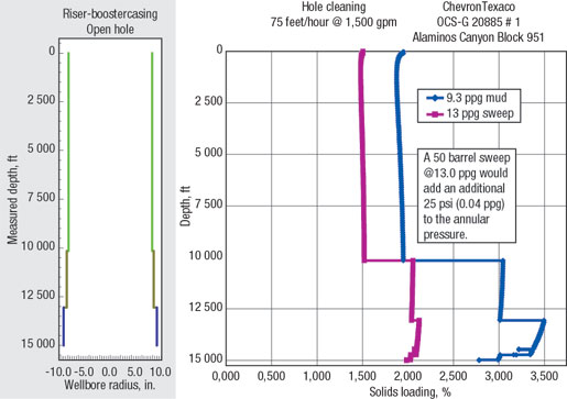 |
Fig. 5. Weighted viscous sweeps increased the ECD and lifted cuttings from the hole.
|
|
Because the initial displacement fluid’s mud weight was 8.5 – 9.0 lb/gal, there was concern about the mud system’s hole-cleaning ability. The goal was to drill the first hole section below the 22-in. casing in one pass (13,054 – 15,004 ft). A pilot test project was initiated to determine the optimal Synthetic-to-Water Ratio (SWR) and product mix for such a light mud weight. A test matrix was established to test with an 8.7-lb/gal fluid at 70:30, 75:25, 80:20 and 85:15 SWRs, using different product mixes to achieve a yield point greater than 20 lb/100 ft2, measured at 120°F.
During testing, a viscosity profile under downhole pressure and temperature conditions was generated on each of the SWRs. The profiles were then used to model ECD and SPP while drilling the first hole section below the 22-in. casing. This interval’s Formation Integrity Test (FIT) was expected to be 10.0 lb/gal. It was determined that maintaining an ECD below 10.0 lb/gal Equivalent Mud Weight (EMW) was achievable with sufficient hole cleaning.
Initial modeling indicated that a flowrate of more than 1,800 gpm was needed to clean the 22-in. hole. This was modeled using a worst-case scenario with a cuttings size of 0.610 in. and specific gravity of 2.5 g/cc. Since a 1,800+ gpm flowrate was not possible, due to circulating equipment restraints, other hole-cleaning methods were investigated. Using the modeling software, numerous simulations evaluated hole cleaning, using weighted viscous sweeps. As an example, two different sweeps were modeled: 50 bbl at 13.0 lb/gal and 30 bbl at 16.0 lb/gal.
Modeling indicated that both sweeps would add 25 psi, or 0.04-lb/gal EMW, to the circulating system. The 13.0-lb/gal sweep simulation reduced cuttings loading to 2% from 3%. A 16.0-lb/gal sweep reduced the loading further to 1.7%. Cuttings loading vs. ROP was plotted to determine the optimal ROP to balance the circulating pressure and ECD. During the execution phase, the section was drilled with a typical ROP of 50 – 75 ft/hr.
LOST CIRCULATION
Although careful engineering and evaluation of drilling fluid properties should reduce drilling-induced lost circulation, the nature of the formations being penetrated is such that losses could not be eliminated. In many instances, the formations are naturally fractured or permeable. Fluid invasion into these voids can add stress to the formation and lead to expensive synthetic losses.
It is paramount that these fractures and pores are effectively bridged-off while drilling these zones. To design and optimize bridging material type and concentration, proprietary software was used. The lost circulation material is added, both as background materials continuously present in the mud, and as remedial additives whenever seepage losses or lost circulation occur.
Another significant feature of the bridging materials is that they must not affect the fluid system’s integrity. By itself, barite is an effective bridging material for certain pore and fracture openings, but barite’s particle size distribution is determined by production specifications and not the wellbore’s pore and fracture openings. Therefore, deliberate additions of optimized concentrations of other particle sizes and shapes were used to effectively bridge-off a wide range of pore openings.
Due to the shaker configuration’s solids removal efficiency, some lost circulation material (LCM) material was unavoidably lost over the shakers.
To help minimize lost circulation, a downhole pressure tool that monitors ECD can be very beneficial. Annular pressure should increase gradually with increased depth. If annular pressure increases at a rate higher than the established trend, and the fluid system’s density and rheology have not changed, this can be an indicator of cuttings accumulation. Appropriate action should be taken in the form of sweeps, increased circulating time between connections, and back-reaming of the last connection. If pressure is not reduced to normal, a short trip to the shoe is recommended while pumping-out the hole.
EXECUTION PHASE
A DKD operation’s fluid volume requirements are high and the ability to provide sufficient volumes with satisfactory fluid properties is critical for this application. Careful logistical planning and drilling fluid supply management is important to ensure that the specified volumes are available when needed. Additionally, mud plant facilities must be flexible, so that changes in operational progress can be managed and accommodated.
Riserless section. Many factors were considered when planning the riserless section. The location’s shallow hazard analysis indicated a low-to-moderate risk for shallow-water flows. With an expected water depth over 10,000 ft, and the logistics concern of being over 230 mi from the supply base, a close investigation of offset well data was initiated. One of the offset wells reviewed was in 9,743 ft of water, where 20-in. casing was set at 2,775-ft BML. In this instance, a 12.5-lb/gal mud was required to trip out of the hole after reaching casing depth.
To get the necessary LOT to drill the first section after running the riser, the 22-in. casing shoe would need to be pushed deeper (~2,900-ft BML) than any of the offset wells. Since the supply base was located far away, the operator planned for the worst-case scenario. This included drilling 2,200 ft of 26-in. hole at 70 ft/hr with 10.5-lb/gal, DKD mud. A total of 27,704 bbl of DKD fluid was shipped to the rig.
After jetting 36 in. to 10,419 ft, drilling with seawater began. At 10,795 ft, a water flow was detected, and drilling with 10.0-lb/gal DKD mud began. High torque was encountered at 11,840 ft, so the mud weight was raised to 10.5 lb/gal and maintained to 13,080 ft TVD. A 12.5-lb/gal pad mud was pumped, and the 22-in. casing was run to 13,033 ft. A total of 18,336 bbl of 16.0-lb/gal DKD fluid was used, and the remaining mud was returned.
18-in. x 22-in. section (17-7/8-in. casing). The well was displaced to a 9.0-lb/gal, synthetic GOM-compliant drilling fluid. An FIT of 9.74 lb/gal EMW, was achieved. This was less than the 10.0 lb/gal planned, making ECD management a concern. Because of this, the viscosity was intentionally reduced. Drilling began at 75 – 80 ft/hr with indications of inadequate hole cleaning. Due to signs of packing-off, the bit was pulled into the casing, and the hole was circulated clean. While washing back to bottom, a 70-bbl, 16.0-lb/gal sweep was pumped. This sweep was made of coarse ground and regular barite.
Minimal improvement was observed, and the mud weight was raised to 9.2 lb/gal. The system’s viscosity was increased as well. It was then decided to pump different sweeps to improve hole cleaning. An increase in mud weight to 9.3 lb/gal, combined with a 100-bbl viscous sweep, weighted to 12.0 lb/gal, was the most efficient for hole cleaning. A large increase in cuttings over the shakers was observed.
These sweeps were pumped for the remainder of the hole section, with a noticeable increase in cuttings when these sweeps reached the surface. Additionally, a reduction in torque and drag, combined with lower ECD, was achieved. A volume of 100 bbl was typically pumped, before making a connection. Continuous pumping of these relatively viscous sweeps raised the mud system viscosity, which was controlled by adding base fluid and emulsifier. This practice was maintained to the casing point.
At TD, the wellbore was circulated clean, and the mud system’s viscosity was reduced. Casing was run and cemented with no problems or mud losses.
12¼-in. x 16½-in. x 19½-in. section (16-in. casing). After drilling out with a 9.3-lb/gal mud, an LOT of 10.97-lb/gal EMW, was achieved. Drilling continued with a 121D4-in. pilot bit and, after drilling several sands, the well began to flow and the MW was raised to 9.8 lb/gal. The mud system’s water content increased 4%, indicating a water flow. The mud system was treated for the water influx and, because of seepage losses, the LCM concentration was increased to ± 20 lb/bbl. The LCM blend included a combination of 3 – 5-lb/bbl fiber, 12 – 15-lb/bbl inorganic mineral and 3 – 5-lb/bbl synthetic LCM. This was done to achieve a PPA value of less than 5.0 ml at 2,500 psi and 250°F, on a 35-micron aloxite disc.
The pilot hole was drilled to 16,662 ft and logged problem-free. In some areas, the sands were washed out to 23 in. The wellbore was then opened to 191D2 in. LCM additions were maintained while pumping viscous weighted sweeps.
A large amount of sand was present throughout the hole-opening operation. At 16,692 ft, the drilling of 191D2-in. hole began, and the viscosity was increased. The mud weight was raised to 10.0 lb/gal at 17,000 ft. In addition, sweeps were pumped every stand (alternating between a 12.2-lb/gal high-viscosity sweep and an LCM sweep).
Since the 16-in. casing depth was to be determined while drilling, a balance had to be maintained between low viscosity for ECD management and hole cleaning requirements. As in the 22-in. hole section, the sweep frequency caused viscosity to increase. This had to be controlled through base fluid and emulsifier additions.
Upon reaching casing point (572 ft deeper than planned), very little circulating time was allowed prior to pulling out of the hole to run 16-in. casing. The MW was raised to 10.2 lb/gal, and a 100-bbl, weighed high-viscosity sweep was pumped prior to the casing run. The 16-in. casing was run to 18,475 ft without any losses. A tight spot was encountered, and the casing had to be washed from 18,475 – 18,626 ft. It was then cemented without returns. A total of 2,790 bbl of synthetic-based mud was lost while running and cementing the 16-in. casing. ECD in this section remained less than 0.39 lb/gal over the actual mud weight.
14¾-in. section. Drilling began at 50 ft/hr, with 10.4-lb/gal mud. A 60-bbl, weighted, high-viscosity sweep was pumped with a slight increase in cuttings. Drilling continued while encountering numerous water flows. These required constant base fluid additions to maintain the desired 75:25 SWR.
Seepage losses were observed, and additional LCM was added to the system. Several 80-lb/bbl LCM sweeps were pumped, alternating with weighted high-viscosity sweeps for hole cleaning. The well was drilled to a 22,695-ft TD, with a final MW of 11.8 lb/gal. ECD in this hole section was maintained at less than 0.38 lb/gal over the actual mud weight. Fig. 6 summarizes the well, as drilled.
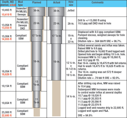 |
Fig. 6. The well was drilled to a total depth of 22,695 ft with a final MW of 11.8 lb/gal.
|
|
CONCLUSIONS
The planning and drilling operation proved successful, including the drilling fluid design for a world record 10,011-ft water depth well. The DKD application used for the upper sections allowed the setting depths of the initial casings to be increased, while eliminating both the 13-5/8-in. and 11-7/8-in. casing strings.
The use of a specifically designed synthetic compliant drilling fluid was instrumental to achieving TD at 26,695 ft. with no HSE incidents. The fluid system performed well and responded to influxes and treatments as expected. The well was finished ahead of schedule with significant savings compared to the original AFE. This was due to reduced mud losses and elimination of two casing strings. 
ACKNOWLEDGMENTS
The authors thank Chevron and Baker Hughes Drilling Fluids for allowing the publication of this article. Many thanks are extended to personnel involved in the technical engineering of the well, both in the planning and execution phases, and from laboratory and base operations to the field. A special appreciation goes to the drilling fluids engineers and crew onboard the Discovery Deep Seas.
This article was prepared from SPE paper 92587-PP, which was presented at the SPE/IADC Drilling Conference in Amsterdam, The Netherlands, Feb. 23 – 25, 2005. P. B. Tanche-Larsen was one of the authors on the original paper.
REFERENCES
1 Johnson, M. and M. Rowden, “System cuts casing run costs,” Hart’s E&P, \March 2002, pp. 77 – 78.
2 Dye, W., G. Mullen, and W. Gusler, “Drilling processes: The other half of the barite sag equation,” SPE paper 80495, presented at the SPE Asia Pacific Oil and Gas Conference and Exhibition, Jakarta, Indonesia, April 15 – 17, 2003.
3 Mullen, G., J. Perez, B. Dye and B. Gusler, “Coupling of technologies for concurrent ECD and barite sag management,” presented at the AADE 2003 National Technology Conference, Houston, Texas, April 2003.
|
THE AUTHORS
|
|
Jeff Dieffenbaugher is the Chevron drilling superintendent assigned to the Transocean Deep Seas. After graduating from Marietta College Dieffenbaugher joined Chevron and has worked in various assignments in California, Texas and Louisiana. He has extensive experience in deepwater engineering and operations.
|
|
|
Ron Dupre is the drilling fluids advisor for Chevron GOM Deepwater and Shelf Business Units. He has over 36 years in the drilling fluids business and has extensive deepwater drilling fluids experience.
|
|
|
Gervais Authement Jr. is the deepwater business development manager for Baker Hughes Drilling Fluids in Houston. Authement joined Milchem after earning his BA in engineering technology from Nichols State University in 1976. He has extensive experience in deepwater drilling fluids operations.
|
|
|
Gregg Mullen has 10 years’ experience with Baker Hughes Drilling Fluids and has been a technical advisor for the last seven years. Mullen has two drilling fluid patents and has authored many industry papers. He earned a BS in civil engineering from the University of Houston.
|
|
| |
Yohnny Gonzale z is the senior operations coordinator for Baker Hughes Drilling Fluids based in Tripoli, Libya. Mr. Gonzales earned a BS degree in petroleum engineering from Universidad in Bogota, Colombia in 1989. He joined Baker Hughes in 1992 as a fluids engineer and worked in Houston from 1997 to 2004.
|
|
|

