Drilling and Completion Technology
Designing limited-entry fracture completions for horizontal wells
LEF is improved with a combination of perforation design and acid soluable cement
Craig Rohwer and Claudia Garces, Halliburton; Hal Crabb III, EOG Resources, Inc.
Many completion techniques have been used for fracture stimulation of horizontal wells. Multiple-stage fracturing treatments are highly effective, but carry high cost and risk that often make it unattractive. Limited-entry fracturing (LEF) has proven to be an effective stimulation method for horizontal wells with an acceptable level of cost and risk.
LIMITED-ENTRY FRACTURING
LEF uses perforation friction pressure to control the stimulation fluid distribution into each perforated interval and has been used successfully for years in vertical wells. In horizontal wells, several LEF characteristics include:
- Fluid friction along the tubulars in long intervals
- Little or no hydrostatic pressure changes along the lateral
- Perforation erosion by proppant slurries.1
Pipe friction in very long horizontal completions is often the limiting factor when determining the maximum treating rate. Perforation erosion, which only has a minor effect on fluid distribution in vertical wells, can significantly affect the fluid distribution in horizontal stimulation treatments.
Because the pressure differential across the perforations is highest in the heel section and decreases to the lowest in the toe section, and because the heel perforations are the first to encounter the sand slurries, the erosional effects of sand slurries will de-burr and enlarge the perforations in the heel section of the wellbore much more than in the toe section. Consequently, more of the fracturing treatment will be placed in the heel section and less in the toe section. Arbitrary allowances can be made for erosional effects by reducing the number of perforations in the heel section and/or increasing the number of perforations in the toe section.
Other factors that affect LEF success are tortuosity or near-wellbore friction (NWF) and stress variances along the lateral. Stress variances and NWF of several hundred psi are not uncommon, and can dramatically affect the fluid distribution during the fracturing treatment. NWF effects are not easily addressed, because their magnitude and location along the lateral are unknown. Completion practices can be implemented to help reduce or minimize tortuosity effects, improving LEF success.
ZONAL ISOLATION
One of the primary concerns in LEF of horizontal wells is adequate zonal isolation. Openhole external casing packers, gel plugs or chemical packers, and cements have all been used with varying degrees of success to control fracture placement at specific intervals along the lateral. Openhole, pre-perforated liner completions have been used as a low-cost alternative, but have had limited success at effectively fracture stimulating horizontal wells.6
Cement is a consistent and reliable method for controlling fracture placement at specific wellbore intervals.3 However, conventional cements can have a negative impact on the completion. Because conventional cements have a low solubility in acid, perforations can be difficult to break down, can inhibit fracture initiation and can cause excess NWF during stimulation and production.
Successful horizontal limited-entry stimulation requires that all perforations be open and in communication with the formation, and that the designed perforation friction controls the fluid distribution along the wellbore. Unopened perforations and NWF from conventional cement tortuosity can alter the fluid distribution and adversely affect stimulation effectiveness. Conventional high-compressive-strength cements with acid solubility of less than 5% cannot be reliably removed. Isolating each perforation set using retrievable tools and balling out the perforations with perf-pack ball sealers is the most reliable method to break down all perforations. This process increases completion time, risk and cost.
A non-standard, acid-soluble cement (ASC) has been used for zonal isolation without impeding stimulation and production.2,3 This cement has a fast solubility rate and is highly soluble (>90%) in acid-based stimulation fluids. ASC has physical properties much like conventional cement. It can be formulated to provide the proper weight, fluid-loss, free water, compressive strengths and pump times for particular well conditions. Slurry densities and yield ratios can range from 13.0 – 15.8 lb/gal and 3.55 – 2.00 ft3/sk, respectively. ASC can also be foamed if lower-density slurries are needed.
The easy removal of ASC from the perforation cluster makes it suitable for limited-entry horizontal applications. Its properties allow for an enlarged area in the annulus immediately adjacent to the perforations, while providing zonal isolation along the wellbore. The dissolved pocket around the casing at the clustered perforation point eliminates tortuosity and fracture-entry pressure effects that could alter the planned limited-entry fluid distribution. Also, the skin effects, reduced near-wellbore conductivity and perforation plugging problems with conventional cements are eliminated.
PERFORATING PRACTICES
Hydraulic fracturing perforating is different from production perforating, and perforating for hydraulic fracturing in horizontal wells also varies from vertical wells. Variables to consider include gun size, perforation phasing, shot density, charge type (entry hole and penetration), perforated interval length, pressure conditions and fracture/ wellbore orientation.
Perforated interval length can affect hydraulic fracturing success in transverse and longitudinal laterals. A perforated interval that is too long can result in multiple fractures in the near-wellbore area.5 Multiple fractures can increase bottomhole treating pressures and NWF, as well as decrease fracture width and fluid efficiency. These conditions can hinder proppant placement and stimulation efficiency. Point-source perforating (PSP) has improved hydraulic fracturing success in horizontal wells.1,3 Limiting the perforated interval length of each perforation cluster to four wellbore diameters or less (usually 1 – 3 ft) reduces or eliminates multiple near-wellbore fractures. Fracture width development at the perforation cluster is increased, improving proppant placement.
When perforating for hydraulic fracturing, deep penetration into the formation is not required, because the fracture initiation point is at the cement/ formation interface and not along the perforation tunnel.4 The hole size chosen for LEF affects the total number of holes in the wellbore and the number of holes that can be placed at each perforation cluster. With smaller hole sizes, more perforations can be used and the designed fluid distribution can be matched closely to the desired fluid distribution. However, the erosional effects and hole enlargement caused by proppant slurries are much greater. When using a larger entry-hole diameter for LEF, hole enlargement and erosional effects are less, and fluid distribution changes are minimized, allowing effective stimulation of the entire lateral.
Perforation phasing also affects the fracturing process. Studies have shown that, if the perforations are within 30° of the preferred fracture direction, near-wellbore tortuosity can be minimized, Figs. 1 and 2. Perforation phasing of 60° or less is preferred.5
 |
Fig. 1. Three fractures were generated along the wellbore shown by this microseismic fracture mapping of a LEF treatment on an un-cemented horizontal well.
|
|
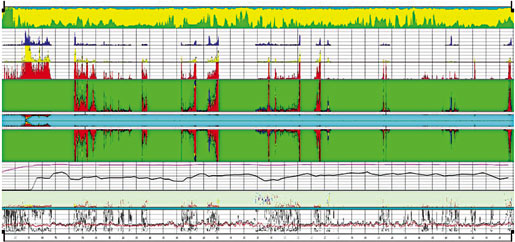 |
Fig. 2. This after-frac tracer log from a limited-entry fracturing treatment on an ASC horizontal well log shows that propped fractures were created at all eight perforation clusters.
|
|
CASE HISTORY
This example focuses on horizontal wells drilled in a 3,550-acre, unitized field in southeastern Lea County, New Mexico. Field development began in 1992 when the first vertical wells were completed in the Third Bone Spring Sand formation. In 2000, there were 39 active, vertical, oil producers in the unit, when the first horizontal well was drilled, Fig. 3.
 |
Fig. 3. A typical well has a 6-1/8-in. hole drilled to 16,500-ft MD, 12,250-ft TVD, with lateral lengths from 1,200 – 6,500 ft. P-110 Hydril liner, 4-1/2 in. by 11.6 lb/ft, is placed from 11,550 ft to 16,500 ft.
|
|
As the project continued, the operator drilled 22 horizontal wells with lateral lengths from 1,200 – 6,500 ft at an average total vertical depth of 12,260 ft. Most of the horizontals wells are producers, but some were converted to injection when a pressure maintenance project began in 2000.
Well planning and drilling. Before drilling the first horizontal well, production engineers used imaging and acoustic logs from vertical wells to investigate fracture orientation in the pay interval. An exact fracture azimuth was not evident, but the general fracture orientation was northeast-southwest. The laterals were drilled with an azimuth of 70° east of north, which was believed to be nearly parallel to the fracture orientation. This direction accommodated the existing vertical wells and was suitable for the pressure maintenance project.
Vertical pilot holes were drilled on some of the wells, and openhole logs were used to determine the target interval thickness, reservoir quality and vertical depth. A well trajectory was then defined using this data and offset well information. As the lateral was drilled, mud loggers gathered geological reservoir information. This would be used later in the perforating and stimulation design process. Openhole logs were not run in the laterals due to the added risk and cost, and because of offset well information.
Zonal isolation. Almost all of the horizontal liners in the field were cemented. Two of the wells were not cemented due to hole conditions and liner equipment problems. At the beginning of the horizontal project, liners were cemented with ASC. After several wells had been drilled and completed, cementing procedures were changed, and conventional cement was used. Later, after frac treatment difficulties on some of the conventionally cemented wells, the cement was changed back to ASC. About half the wells were cemented with conventional cement and half with ASC.
The job procedure for cementing liners was essentially the same regardless of the cement used. Cements were batch-mixed and densities measured with pressurized mud scales before pumping downhole. The cement was preceded with a weighted spacer to aid mud displacement and hole cleaning. Pump rates were similar, typically 5 bbl/min. Slurry volumes were calculated to circulate cement to the liner top plus another 200 ft above. After the cement was displaced and the liner wiper plug landed, the liner hanger packer was set and excess cement was circulated out.
The liner was successfully cemented if no unusual events occurred during the job and if cement was circulated off the liner top after the liner hanger packer was set. Cement bond logs were not run due to risk, tool availability and additional completion time.
Completion methods. Completion procedures for the conventional cement and ASC wells were similar. First, a liner cleanout trip was made and the liner, casing and tubing were pickled with xylene and hydrochloric acid. Acetic acid was spotted in the lateral, and several sets of tubing-conveyed perforating guns (TCP) were picked up and run in the lateral in one trip. Pumping equipment activated the pressure-actuated TCP guns, perforating the liner at multiple points along the wellbore’s horizontal section. Then, the perforations were broken down by pumping away the acid. The guns were removed, frac equipment was rigged up and the hydraulic fracturing treatment was pumped down the casing and liner.
Perforation and frac design. The LEF design process addressed lateral length, pay thickness and pay quality along the lateral, fracture gradients, reservoir pressures and wellbore tubulars. The number of perforation clusters or fractures be placed along the lateral was affected by the length of the lateral and the wellbore configuration. Information from previous fracturing and 3D fracture models indicated that a minimum rate of 10 bpm or greater was required to effectively fracture stimulate a perforation cluster.
Wellhead treating pressures were limited to the pressure rating of the casing minus a safety factor. A maximum surface treating rate was calculated using anticipated bottom hole treating pressures, friction pressures and maximum wellhead pressure limitations. This rate determined the number of perforation clusters that could be placed along the lateral for effective fracture stimulation.
Information from log cross-sections of vertical wells and from a 3D reservoir model was used to estimate pay thickness. Perforation cluster points were spaced as evenly as possible along the horizontal, while keeping them in the thickest and best- quality pay.
Once cluster locations were determined, engineers used a 3D fracture model to design the treatment for each cluster. Because the horizontal wellbores were believed to be aligned with the preferred fracture plane, and the cluster spacing was about 400 ft, individual fractures were designed for a 175-ft propped-wing length. This resulted in a series of nearly-connecting, longitudinal fractures along the lateral length. Fluid and proppant volumes for each fracture were combined into a single, high rate, limited-entry treatment schedule.
Perforation design for conventional cement and ASC wells used the same spreadsheet calculations. Information input into the spreadsheet was used in calculating the number of holes needed at each cluster location for the desired rate distribution, Table 1.
| TABLE 1. Sample data from part of a limited-entry perforation design spreadsheet |
 |
|
The designed treatment rate into the first two or three perforation clusters nearest the heel was reduced slightly to compensate for the rate increase from the proppant slurry’s erosional effects and hole enlargement, Fig. 4.
 |
Fig. 4. The treatment rate into the perforation clusters nearest the heel was reduced to compensate for the rate increase from the proppant slurry’s erosional effects and hole enlargement.
|
|
Perforation gun sizes, charge types, entry-hole diameters, and phasing were the same for all wells of like liner sizes throughout the project. The point-source perforating (PSP) technique was used to reduce or eliminate multiple fractures and allow maximum fracture width development at the perforation cluster. Perforation shot density and phasing was six shots per foot and 60° when there were six or more holes in a cluster. For clusters having four or fewer holes, shot density and phasing was three shots per foot and 120°. This practice limited the perforated interval length to 1.5 ft or less and ensured 360° radial coverage at the cluster.
Perforating and breakdown. The process used to shoot and break down the perforation clusters on conventional cement liners differed from that used on ASC liners. On a typical ASC liner, 6,000 to 8,000 gal of 10% acetic acid would be spotted in the wellbore. Pressure-actuated TCP perforating guns with time-delay firing heads were run in the lateral. The firing heads were pinned to fire sequentially from the deepest perforation cluster to the shallowest (toe to heel). This sequential firing order and the time-delay firing heads allowed a significant volume of acid to be pumped through the toe perforation cluster before the next set of guns fired.
To help ensure that all perforations were broken down, pump rates and pressures exceeding fracture initiation pressure were maintained during the perforating process until all of the guns had fired and the 10% acetic acid was displaced from the liner. The volume of acetic acid used should have been sufficient to dissolve a small pocket of ASC in the annular space immediately adjacent to each perforation cluster.
On wells with ASC, a 12,000 to 16,000-gal stage of 7.5% HCl was pumped immediately ahead of the main fracturing treatment to further clean the clusters. This fluid was pumped at the designed LEF rate to increase the pressure differential across the perforations. This helped ensure that all perforations were accepting acid and that the ASC material behind the perforations was being removed.
Wells cemented with conventional cement were also perforated using pressure-actuated TCP guns with time-delay firing heads. Smaller acid volumes (typically 1,000 gal) were spotted in the wellbore and pumped away during the perforating process due to the low acid solubility of conventional cement. The firing order of the TCP assembly was set to fire the toe gun first and allow most of the spot acid to be pumped through this perforation set before the remaining guns fired. This was to help ensure that the deepest perforation cluster was broken down and accepting fluid.
Further breakdown and cleanup of the perforations was attempted with an acid ball-out job. This treatment was performed with the frac equipment the day before the main frac job. A typical acid ball-out treatment consisted of 12,000 gal of 15% HCl pumped at 10 to 20 bbl/min. Biodegradable perforation ball sealers were injected throughout the acid stage, and the acid was displaced from the wellbore with treated water.
Fracturing treatments. Treatments on the horizontal wells were essentially the same regardless of cement type. With the exception of the acid spearhead for ASC wells and the acid ball-out for conventional cement wells, fluids for all fracturing treatments consisted of slick water and low-polymer, delayed, crosslinked borate gels.
Several proppant types were used, ranging from resin-coated intermediate-strength ceramics to lightweight ceramics with mesh sizes ranging from 20/40 to 16/20 mesh. Most of the wells were treated with 18/40 intermediate-strength, ceramic proppant. All of the wells were treated down the casing and liner with designed rates ranging from 60 to 120 bbl/min.
OBSERVATIONS
At the beginning of the horizontal drilling project, liners were cemented using ASC. Fracture treatments were pumped to completion, with rates and pressures close to those predicted by the design, Fig. 5. After several wells had been drilled and completed, liner cementing practices were changed and conventional cement was used. Fracture treatments on the conventionally cemented wells were not often pumped as designed and pumping schedules were frequently changed during the job to adjust for the lower rates and higher pressures encountered, Fig. 6.
 |
Fig. 5. Fracture treatments were pumped to completion, with rates and pressures close to those predicted by the design.
|
|
 |
Fig. 6. Often the designed treatment rate was not reached until the end since pumping schedules were frequently changed to adjust for lower rates and higher pressures.
|
|
After reviewing fracture treatment job data from the completed wells, engineers noted that wells with conventional cement always had significantly higher observed bottomhole treating pressures (BTP) than predicted. Observed BTP on ASC wells were usually within 300 psi of the predicted pressures.
The difference between the observed and predicted BTP was defined as Entry Friction (EF). This EF averaged 1,250 psi for conventional cement wells and less than 300 psi on ASC wells, Fig. 7. The high EF on the conventional cement wells was attributed to NWF caused by excess tortuosity and perforation friction from holes that were not accepting fluid.
 |
Fig. 7. Average entry friction for ASC wells was 300 psi. Average EF for conventional cement wells was 1,200 psi.
|
|
Proppant slugs were pumped during the pad in all of the treatments to reduce tortuosity effects and multiple fractures. Upon reviewing the fracture treatment data, the slugs had little effect on ASC wells, but significant effects on conventional cement wells. This indicated that tortuosity and multiple fractures were much more prevalent in conventional cement wells.
Although both types of wells were perforated using the point-source perforating technique and perforations were broken down and acidized, the ASC wells treated much closer to predicted pressures. The unique properties of ASC allowed it to be dissolved from the annulus at the perforation cluster, reducing or eliminating tortuosity and helping ensure that each perforation was open and in direct communication with the formation.
CONCLUSIONS
LEF can be used to effectively stimulate horizontal wells. The success of LEF treatments can be affected by the zonal isolation and perforating methods used in the completion.
The point-source perforating (PSP) technique improves LEF success on horizontal wells. However, point-source perforating by itself does not necessarily eliminate EF.
Horizontal wells with ASC had significantly less EF and treated much closer to predicted pressures than conventional cement wells. ASC can improve fracture effectiveness by reducing tortuosity and unopened perforations.
As a result of this study, cementing procedures for horizontal wells drilled in the unit have used ASC. Zonal isolation is now used on the majority of the operator’s wells that are stimulated using LEF. 
ACKNOWLEDGEMENTS
The authors thank Halliburton for the opportunity to publish this article, and all at Halliburton who helped. Special thanks to EOG Resources, Inc. for permission to publish and also to Jim Blair, Protechnics, for his contribution.
REFERENCES
1 McDaniel, B.W., Willett, R.M., Underwood, P.J., “Limited-Entry Frac Applications on Long Intervals of Highly Deviated or Horizontal Wells,” SPE 56780 presented at the SPE Annual Technical Conference and Exhibition, Houston, TX, Oct. 3 – 6, 1999.
2 Willett, R.M., Borgen, K.L., McDaniel, B.W., “Effective Well Planning and Stimulation Improves Economics of Horizontal Wells in a Low-Permeability West Texas Carbonate,” SPE 77932 presented at the Asia Pacific Oil and Gas Conference and Exhibition, Melbourne, Australia, Oct. 8 – 10, 2002.
3 Smith, W.R., Borgen, K.L., Willett, R.M., McDaniel, B.W., “Unique Engineered Completion Using Horizontal Cemented Liners Improves Stimulation in West Texas Low-Permeability Carbonate Reservoirs,” presented at the Southwest Petroleum Short Course, Lubbock, TX, April 2003.
4 Van Gijtenbeek, Klass A.W., Pongratz, R., “Perforating and Hydraulic Proppant Fracturing in Western Siberia, Russia,” SPE 90238 presented at the SPE Annual Technical Conference and Exhibition, Houston, TX, Sept. 26 – 29, 2004.
5 Underwood, P.J., and Kerley, L., “Evaluation of Selective vs. Point-Source Perforating for Hydraulic Fracturing,” SPE 36480 presented at the SPE Annual Technical Conference and Exhibition, Denver, CO, Oct. 6 – 9, 1996.
6 McDaniel, B.W., East, L., Hazzard, V., “Overview of Stimulation Technology for Horizontal Completions Without Cemented Casing in the Lateral,” SPE 77825 presented at the Asia Pacific Oil and Gas Conference and Exhibition, Melbourne, Australia, Oct. 8 – 10, 2002.
|
THE AUTHORS
|
 |
Craig Rohwer is technical advisor for Halliburton Energy Services in Midland, Texas, and is responsible for developing engineering solutions for drilling, completion and production operations in the Permian Basin. Rohwer has 14 years’ experience with Halliburton in various operational, business development, and technical positions. He earned a BS degree in mechanical engineering from the University of Texas at Austin.
|
|
 |
Claudia Garces is principal technical instructor for Halliburton in Fort Worth, Texas, and is responsible for developing and delivering production enhancement training, educational programs and advanced technical on-the-job training for external customers and internal employees. Garces joined Halliburton in 2002 in West Texas as a production enhancement and cementing engineer. She earned a BS degree in petroleum engineering from The Universidad Industrial de Santander in Bucaramanga, Colombia.
|
|
 |
Hal Crabb III is a division production specialist with EOG Resources, Inc., in Midland, Texas. He has been with EOG for 15 years in production, completion and acquisition. Crabb has more than 26 years of industry experience in West Texas and Southeast New Mexico and earned a BS degree in mechanical engineering from the University of Texas.
|
|
|

