Drilling and Completion Technology
Combined UBD and drilling with casing lends innovation to unique conditions
A unique combination of underbalanced drilling and drilling with casing has proved to be successful in drilling wells that feature stratified pressure regimes in mature fields, including CO2
Chris Chandler and Doug Genrich, Anadarko Petroleum Corp.; Alejandro Coy, BP America; and George Doty, Jim Stanley and Steve Rosenberg, Weatherford International
The combination of two innovative technologies, Underbalanced Drilling (UBD) and rotary drilling with casing, has proved to be a viable solution to successfully drilling a well with varying stratified pressure regimes, including CO2, in a mature field. A project to prove this innovation had the following objectives:
- Minimize drilling-induced formation damage to maximize injection capabilities
- Minimize induced losses, thus differential sticking
- Improve drilling efficiencies by reducing flat time caused, NPT, well conditioning, drillstring tripping and casing running operations.
The case study described in this article shows how a gas injection well overcame the challenges of conventional drilling approaches that were potentially costly and challenging from a well control perspective, due to lost circulation and the resultant formation influxes. In addition, because drilling took place with the casing string, the operator, Anadarko Petroleum, did not have to be concerned with any potential well control problems. Such problems would be due to surges while tripping conventional drillstring, short trips to condition the well and/or the casing running, itself.
To account for potential surface pressures, due to the differential between the mud column and pore pressures, the operator used a closed-loop, pressurized separation system at the surface to manage potential flow and pressures. Although the technical capabilities of the separation system exceeded the well’s potential flowrates and pressures, this virtually assured well control at all times.
As a result of applying the combination of UBD and rotary drilling with casing, the operator successfully drilled and cased the well to TD. Compared with conventional drilling practices employed in the area, the operator benefited by:
- Not having to kill the well to run the casing string (Note: The well was killed prior to cementing.)
- Significantly eliminating fluid lost into the formation
- A potential for improving injection capabilities
- Reduced flat time
- Observed, excellent hole cleaning
- improvement in the cement job and bond log, which is an issue in the field
- Managing produced fluids and formation pressures, using a pressurized separation system.
Operational benefits, productivity increases and savings (monetary and time) arising from drilling underbalanced with rotary casing are potentially crucial to the future viability of drilling these types of wells in mature fields. Equally important, and not to be understated, this was an immense success from a Health, Safety and Environmental (HS&E) perspective. Due to drilling the well in a controlled environment, the project experienced no issues caused by CO2 freezing of pipes at the surface.
Located north of Casper, Wyoming, Salt Creek field uses CO2 and water injection for flooding purposes. Due to the expected overpressured reservoir, maintaining equilibrium conditions to avoid losses posed a major challenge. These conditions in wells previously drilled required high mud weights to control CO2-pressured zones. This resulted in frequent differential sticking across non pressured zones.
What follows is a discussion of the well design and the associated challenges with UBD conditions using casing as a rotary drilling string. The time and costs savings, and operational results achieved, using this innovative approach, resulted in very efficient reservoir protection and enabled the successful drilling of a problematic well.
PLANNING
Well planning included a detailed study of the different pore pressure regimes in the reservoir, and flow modeling calculations with varying sensitivities, to determine the appropriate drawdown with a drilling fluid density of 8.6 ppg to ensure that the 5-in. casing and connection could withstand the task. The specially designed casing drilling shoes provided a viable alternative. However, offset well bit analysis resulted in the selection of a conventional PDC bit, due to the abrasiveness and formation hardness in the well’s last section.
PROBLEMS IN OFFSET WELLS
Due to the CO2 flooding in the area, drastic surface pressure drops can cause the lines to freeze, especially while drilling out of the 7-5/8-in. shoe. Typically, the operator hooks up a glycol pump upstream of the choke manifold to mitigate the freezing potential.
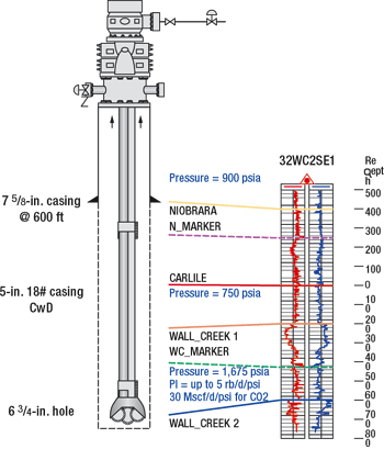
However, the pressure in the Niobrara Shale at around 500 ft could, in theory, be as high as 1,300 psia. This assumes that CO2 flows from the Wallcreek 2 (WC2) up to the Niobrara, and has the hydrostatic head of CO2 at pressure and temperature from WC2, upward. Realistically, though, CO2 flows in the Niobrara would be at a pressure similar to overburden pressure from sonic logs, estimated at 550 psia, Fig. 1.
The expected produced fluid was mostly CO2 with some water. The geothermal gradient suggested approximately 70°F in the Niobrara, with no CO2 flow, but the temperature could be around 30°F, if CO2 is flowing at 550 psia.
EXISTING WELL CONDITIONS
With 10-3/4-in. casing set at 180 ft, the operator drilled a 9-7/8-in. vertical hole to 604 ft; encountered a flow resulting in 18.2-ppg kill fluid; cased this section with 7-5/8-in., 26.4 lb/ft BTC HCP 110 casing; and released the rig. The plan was to drill down to 2,300 ft and set 5-in. casing to TD.
Since the well sat in the middle of a CO2 injection field with projected bottomhole pressures equal to 17 to 18 ppg, the operator solicited alternatives to conventional drilling practices. The operator selected UBD with the 5-in. casing string.
RESERVOIR/ PRODUCTION DATA
At Wallcreek 2 (WC2), the following data were observed:
- Pressure was 1,675 psia at the top of WC2 (determined from a monitor well). Pressure did not change considerably, and top WC2 elevation was similar to an offset well.
- PI equalled up to 5 bpd/psi, unstimulated, for liquids, or 30 Mcfd/psi for CO2. Oil and hydrocarbon gas are not significant for IPR purposes.
- CO2 liquid ratio equalled 0. Most likely, there was no gas, but there could be anywhere from no gas to about 4,000 scf/bbl.
- Reservoir temperature = 100°F
Data observed at Wallcreek 1 (WC1) included the following items:
- Pressure equalled 750 psia at the top of WC1, estimated from 0.435 psi/ft gradient.
- PI equalled up to 5 rb/d/psi, unstimulated, for liquids, or 30 Mcfd/psi for CO2. Oil and hydrocarbon gas were not significant for IPR purposes.
- Expected gas/liquid ratio equalled 0-50 scf/stb (relatively low).
- Reservoir temperature was 95°F.
Finally, data recorded for the Niobrara Shale (all calculations at 500 ft) were as follows:
- Pressure equalled 550 psia (estimated from sonic logs).
- PI was unknown.
- Engineers generally expected CO2, and possibly water.
- Temperature equalled 30°F, when CO2 flowed at 550 psia. Geothermal gradient suggests about 70°F, if CO2 is not flowing.
UBD DESIGN
All hydraulics calculations incorporated an 8.6-ppg mud with low plastic viscosity and yield point. In Table 1, various calculated results help to determine sensitivities for applying back pressure while drilling with casing.
| TABLE 1. Well sensitivity at varying applied choke pressures. |
 |
|
As seen in Table 1 and the graphs included (Figs. 2, 3 and 4), a wide operational envelope exists. Basically, the well response and performance dictate the applied operational parameters once the reservoir fluid starts flowing. Since real-time, bottomhole pressure-while-drilling (PWD) was not possible for this project, the flow modeling during the operation will be key to a successful UBD operation, as well as the main tool for the UBD applications engineers in their decision-making process(es).
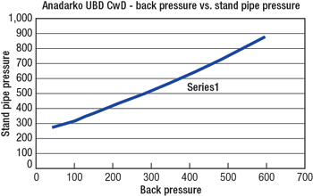 |
Fig. 2. Back pressure vs. standpipe pressure.
|
|
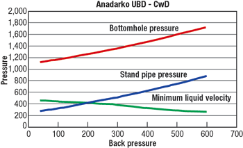 |
Fig. 3. Back pressure vs. annular liquid velocity
|
|
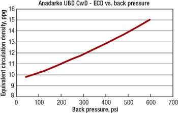 |
Fig. 4. Backpressure vs. ECD
|
|
Several observations were made from a production sensitivity standpoint. For instance, allowing the well to flow at high rates causes the annular fluid system to reduce the Equivalent Circulating Density (ECD). This results in using higher backpressure values to compensate for the loss of effective fluid density.
Additionally, the flow drilling process perpetuates itself until the hydrostatic pressure, plus friction losses, plus wellhead pressure equals the downhole pore pressure(s). Once this occurs, influx of fluids into the wellbore from the formation will cease, as the resultant bottomhole pressure equalizes formation pressure.
Finally, upon establishing flow drilling, i.e. once formation fluids are flowing into the wellbore, the annular velocity increases. This helps to transport cuttings uphole in a more efficient way, due to the small annulus between the 5-in. casing and the 6-3/4-in. hole.
The modeled results shown in Figs. 2, 3 and 4 were completed during the planning phase, enabling the prediction and possible understanding ahead of time of how the different conditions in the well interact with each other.
FLOW CONTROL MATRIX
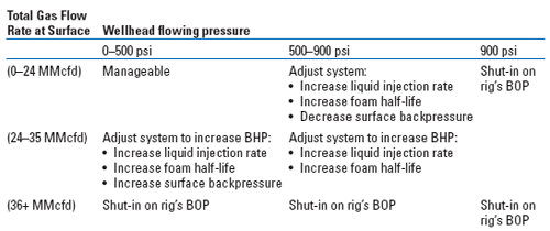
Wellhead pressures and returning gas flowrates determined the UBD equipment selection, to ensure continuous, safe drilling operations. The Flow Control Matrix (Table 2) defined these parameters for drilling operations.
| TABLE 2. Flow control matrix. |
 |
|
This project required a risk-based approach to the Flow Control Matrix design. One of the design parameters was a maximum flow capacity of the surface separation system that included a safety factor. Another parameter was a pressure rating on the flow control equipment (such as an ESD valve), UBD choke manifold and primary flowline. Yet another factor was the maximum permissible erosion rates of the surface flowline(s) and manifolds. One final consideration was maximization of the service interval for the rotating diverter.
The Flow Control Matrix established flow control actions as functions of gas flowrate at surface, and flowing wellhead pressure during the drilling of the well. The adjustment regions, indicated in yellow, established a safe-reaction time allowance to return operations to a green light condition. The red shaded areas indicated well control events.
SURFACE LAYOUT
After reviewing all of the possible downhole scenarios, the resultant surface system design consisted of the following equipment, Fig. 5:
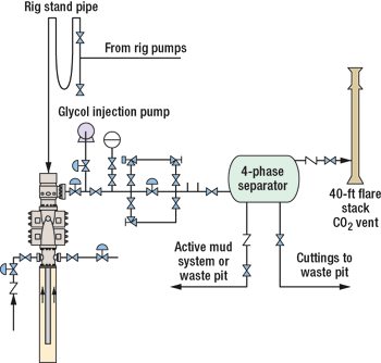 |
Fig. 5. Surface system layout.
|
|
- Weatherford IP 1000 rotating control device, 10,00-psi dynamic/1,500-psi static
- 3,000-psi choke manifold
- Pressurized separation package, able to handle 40 MMcfgd and 20,000 bpd of liquids
- 4-1/2-in. FH x 5-in. DwC/C crossover, to connect the rig’s top drive to the 5-in., 18 lbs-ft, L-80, DwC/C casing, and rotate the casing. The DwC connection is a modified buttress thread with a torque shouldering system, providing greater fatigue resistance and torque strength for drilling with casing applications.
OPERATION
With 10-3/4-in. casing set at 180 ft, the operator drilled a 9-7/8-in. vertical hole to 600 ft, encountered a flow resulting in 18.2-ppg kill fluid, cased this section with 7-5/8-in., 26.4 lbs-ft BTC HCP 110 casing and released the rig. The plan was to drill down to 2,300 ft and set 5-in. casing to TD.
Since the well was located in the middle of a CO2 injection pattern, with projected bottomhole pressures equivalent to 17 to 18 ppg, the operator solicited alternatives to conventional drilling practices. The decision was made in favor of a control pressured environment that eliminated the need for trips as the preferred option.
Upon evaluating the various options, and completing the underbalanced and rotary drilling with casing plan, the operator contracted a drilling rig to resume operations. Prior to commencing operations, the crews went thorough CO2 and H2S training.
The operator picked up a 6-3/4-in. PDC bit and ran in the hole with 5-in. casing to the top of the cement at 483 ft. Drilling operations resumed by drilling cement down to the 7-5/8-in. casing shoe at 604 ft. Drilling operations inside the 7-5/8-in. casing were uneventful, and the operator continued drilling openhole section to 2,060 ft without recording any annular pressures from the well, directing all returns through the closed loop system. Drilling from 2,060 ft to TD at 2,300 ft, 100 psi of backpressure were applied to control formation pressure. During connections, the maximum shut-in pressure was 460 psi.
The underbalanced rotary casing drilling took 35.5 hr to drill the 121 ft of cement, float equipment and 1,696 ft of new formation, with no problems recorded. The average rate of penetration was 54 ft/hr. There were 9 hr, downtime, waiting on kill mud prior to cementing. Total time for cementing to setting slips was 3 hr after the well was TD’d.
This project incorporated the benefits of UBD (increased rate of penetration, managed well control and minimal formation damage) with the operational benefits of rotary drilling with casing (no well conditioning trips, pipe laydown operations, excellent hole cleaning, better cement bond logs) with surface returns managed through a pressurized closed-loop system.
CONCLUSIONS
The overall underbalanced and rotary drilling with casing operation was very successful and may be an integral part of future operations. Several lessons resulted.
First, although the well did not meet predictions for higher reservoir pressures while drilling in the well‘s shallow portion with a lighter fluid gradient, the rotating control device and the closed loop separation system, upon encountering pressure, safely controlled both pressure and flow. This allowed the normal continuation of underbalanced and rotary casing drilling operations. Typically, conventional drilling calls for ceasing drilling activities and controlling the well, all resulting in additional costs for weighted fluid and rig time, due to non-productive time (NPT) operations.
Second, additional safety benefits came from reducing the exposure of the drilling and service company’s crews to pipe trips and rig up of casing running equipment. Also, planning for the “worst case” scenario resulted in over-designed surface equipment on the well; in a multi-well drilling program, there is opportunity to take the lessons learned from this single-well project and optimize the surface equipment, capitalizing additional cost savings. Safe drilling of the well’s production interval with the closed loop system enabled the safe management of any gas and fluids returns to surface.
Third, underbalanced and rotary casing drilling improved drilling penetration efficiencies (ROP). The average ROP for the openhole section was on the order of 54 ft/hr, comparable to those seen in an offset well using a downhole motor (59 ft/hr), but significantly higher than the average rate with conventional drilling of 28 ft/hr. Additionally, flat time was reduced further by eliminating the NPT associated with well control and differential sticking. Once the well reached TD, it took only 3 hr to complete the cement job. In conventional drilling, this would have taken longer, considering conditioning trips, laying down of the drillstring, rig up of equipment to run casing and running the casing, itself. In today’s market, time savings such as these can make an important difference in the overall operational costs.
The operator does not regard formation damage as a major problem in the field since most wells are stimulated. Further analysis is required to assess whether the underbalanced operation has potential injection benefits by minimizing or eliminating fluid lost into the formation. 
This article is based on a paper that was prepared for presentation at the 2006 Offshore Technology Conference, held in Houston, Texas, USA, May1 – 4, 2006.
|
THE AUTHORS
|
|
Doug S. Genrich, P.E., is a drilling manager for Anadarko Petroleum in Algeria. Previously, he was the Rockies drilling manager for Anadarko, based in The Woodlands, Texas. He has 18 years of diverse experience in drilling and production operations, working the majority of the US basins, plus the Gulf of Mexico, Qatar, and Algeria. Mr. Genrich graduated with a BS degree in petroleum engineering from the University of Texas at Austin in 1987. He is a member of SPE and AADE.
|
|
|
Alejandro Coy is a senior drilling engineer, working with BP America on the Tuscaloosa HP/HT project. He joined Weatherford in 2002 and worked on different UBD projects in the US and overseas as engineer/ project manager and technical manager. Prior to joining Weatherford in 2002, Mr. Coy worked at BP for 11 years as drilling, workover and completions supervisor in the field, project engineer on the incident avoidance team in Bogotá, and well interventions engineer on the well management team. He was transferred to the US Mid-Continent Business Unit as drilling engineer, where he later functioned as drilling/ completions engineering team leader in the Anadarko asset. Mr. Coy holds a PE degree from the University of America (Colombia), and is the author of several technical papers and a patent application in underbalanced drilling.
|
|
|
George N. Doty is technical specialist for Weatherford International’s Underbalanced Drilling group. He has 32 years of experience in the upstream sector of the oil and gas industry. His areas of expertise include drilling fluids, solids control, waste management and underbalanced drilling systems. Mr. Doty is a Dallas, Texas, native and graduate of the University of Texas at Arlington. His experience includes time in the Rocky Mountains, Mid-Continent, West Texas and Gulf Coast regions of the US.
|
|
|
Steve Rosenberg is senior drilling engineer at Weatherford International Ltd. He has been with Weatherford for three years and is project manager for the company’s drilling with casing and drilling with liner operations. Prior to joining Weatherford, he held the position of senior engineer at Diamond Offshore and Dupont. Mr. Rosenberg also held the positions of production engineer and drilling engineer at Conoco for several years, earlier in his career. He holds a BS degree in petroleum engineering from Mississippi State University.
|
|
|

