Completion/ Stimulation Technology
Barnett Shale fracture fairways aid E&P
Production is improved by enhancing complex natural fractures.
Kevin Fisher, Pinnacle Technologies, Houston
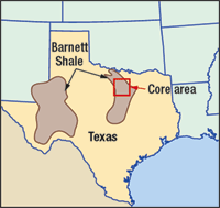 |
Fig. 1. The Barnett Shale is being developed in the “Core” area of Wise/ Denton and northern Tarrant Counties of Texas (outlined).
|
|
Well over 50 operators have drilled or permitted in the Barnett Shale trend of north Texas’ Fort Worth basin since the beginning of 2004, according to Dr. Michael Wayne of Rig Data. As a relatively new unconventional natural gas play, the Barnett has gained national attention, due to the commercial success of operators over the last six years. Over 75% of the producing wells in the Barnett have been drilled since 2000. In 2002, according to the Energy Information Administration, Newark East Field produced 202 Bcf. This was more than any other field in Texas, making it the seventh largest gas producer in the US. The “Core” area of the trend is in Wise/ Denton and northern Tarrant Counties of Texas, Fig. 1.
The Barnett is an ultra-low permeability, naturally fractured reservoir that cannot be produced economically unless hydraulically fractured. The use of “light sand” or waterfrac treatments has considerably improved both the production performance and the economics in this reservoir.
Because of its extremely low permeability, the drainage distance from a fracture face is very small, implying the need for a very large contact area with the reservoir to achieve commercial production. Fortunately, a fracture treatment in the Barnett is more likely to be very complex rather than simple – this allows a fracture “fairway” to be created during a treatment, with a tremendous surface area created from many fractures at different orientations, all contributing to production. Pinnacle has mapped more than 300 treatments in the Barnett and is gaining a better understanding of how these fractures grow and of the area contacted by fracture fairways.
BARNETT BASICS
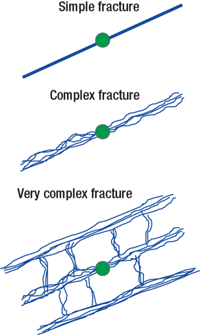 |
Fig. 2. Most mapped fractures fall into the simple category. However, the Barnett has very complex fracturing that creates a large network or “fairway” of multiplanar fractures.
|
|
The Barnett Shale is a marine shelf deposit of Mississippian age that lies unconformably on the Ordovician-age Viola Limestone/ Ellenburger Group. It is overlain conformably by the Pennsylvanian-age Marble Falls Limestone. The formation within the Fort Worth basin ranges from 200 ft to 800 ft in thickness, and is about 300 ft to 500 ft thick in the Core. The productive zone is described as black, organic-rich shale composed of fine-grained, non-siliciclastic rocks with extremely low permeability, ranging from 0.00007 to 0.0005 md.
The Barnett is believed to be its own source rock and is abnormally pressured in the Core. It is somewhat naturally fractured, which causes fracture growth in a very complex style, Fig. 2.
FRACTURE FAIRWAYS
Fracture mapping in the Barnett usually consists of either surface tiltmeters or microseismic mapping to determine primary and secondary fracture orientations. Natural fractures in the basin are oriented orthogonal (NW to SE) to the primary hydraulic fracture orientation (NE to SW). These may be opened during a treatment.
Measuring the length, width and azimuth of the fracture fairway is important for determining the contact area’s extent and location with the fracture network, so that well spacing and drilling locations can be optimized. This is valuable in early exploration, to ensure that wells are drilled in favorable locations and orientations for horizontal wellbores.
Because of the small drainage distance from a fracture, due to extremely low permeability, the fractures density within this fairway is also important. There are opportunities for additional infill wells in less densely fractured areas within a fairway, or for refracs to extend the fairway or to more densely populate it with new fractures.
Surface tiltmapping is a direct fracture diagnostic tool, which is used on more than 2,000 treatments each year (>10,000 treatments in the past decade) to map the surface deformation caused by hydraulic fractures or subsurface dislocations.
The tiltmeter is a very sensitive device, similar to an electronic carpenter’s level, that can sense changes in the displacement gradient (or tilt) of as little as one part per billion. Surface deformation directly determines the azimuth(s) of a hydraulic fracture and the percent of treatment volume placed in each plane or orientation, when fracture growth occurs in multiple planes.
Surface tilts are valuable in determining how the fracturing volume is distributed – does the frac grow only at the toe or heel, or does it effectively cover the entire interval? The fracture orientation is the same as the observed “trough” seen at the surface. Surface tiltmapping provides direct measurement of fracture orientation(s) while dimensions are measured by tiltmeters placed in offset wells or in the frac well itself.
Microseismic mapping has been utilized for more than 20 years to measure the location of micro-earthquakes or microseisms, which result from hydraulic fracturing. These small slippages are detected by a vertical array of 12 or more geophones or accelerometers, placed in an offsetting wellbore.
After orienting each tool in the array (the perforating procedure in the treatment well is used to orient the three-component sensors), microseisms created by the fracture treatment are detected, oriented and located within the reservoir. As the treatment proceeds, a map of the event locations develops, which provides time-based measurements of the fracture azimuth and dimensions.
The data set of a vertical well’s frac treatment, Fig. 3, illustrates the fracture growth complexity in the Barnett Shale.1 The points represent discrete microseismic events detected by the geophone array and are located on the map in real time. The width of this fracture fairway is wide, about 900 ft across. The fairway half-length is long, more than 2,000 ft, for a total fracture length from NE to SW of nearly a mile – a very large swath.
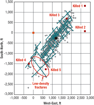 |
Fig. 3. Microseismic events (gray) identify the interpreted NE and NW fracture structure trends in a single Barnett treatment. Fracture fluid contacted the five “killed” wells during the treatment, providing direct evidence of the fracture networks created.
|
|
A new technique was developed to look at fracture growth with time. Small groups, in this case 40-event packets, are fit into a linear regression model to determine the length and orientation of the fracture structures as they are being created. This fracture treatment was confined within the Lower Barnett and covered the entire targeted pay, creating a wide, complex fairway with fractures growing in multiple orientations.
The map view in Figure 4 shows the microseismic results from seven fracture treatments in the Lower Barnett.1 Several “holes” in the fracture fairway are visible, even accounting for observation well bias. These holes (or fairway “bunkers”) may be due to lack of seismicity, acoustic attenuation or a lack of fracture network in these areas. These are targets for refrac treatments and/or new drilling to more completely drain this field. Combining fracture diagnostic technologies across a field is useful in ensuring that we “use the entire fairway” to maximize fracture network coverage. One can easily see how using mapping data helps operators determine the number of wells to drill, well spacings and the relative orientations to one another.
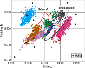 |
Fig. 4. Microseismic events from seven fracture treatments reveal several areas, where refracs (red ovals) or infill drilling locations (black oval) are possible.
|
|
To determine the most important fracturing parameters, numerous correlations were performed to link direct fracture measurements to productivity.1 The strongest correlations to production were to the fracture fairway width (NW to SE spread of microseismic events) and to the increased NW frac volume component measured in surface tiltmapping.
That correlation shows the cross-cutting natural fractures that were activated and dilated during the treatments, Fig. 5. These appear to be important drivers of well productivity. In a typical tight gas reservoir, fracture half-length is the best correlative parameter to production, but the Barnett is clearly different from typical tight gas reservoirs.
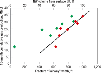 |
Fig. 5. This graph shows good correlation between the fracture fairway “width” (red), measured by microseismic mapping, and NW to SE oriented frac volume placed (green), measured by tiltmapping after 10-months cumulative production.
|
|
HORIZONTAL DRILLING
In most areas of the Barnett, horizontal drilling is used to optimize gas production.2 Issues, such as nearby water-bearing intervals, inadequate surface locations, improved gas production rates and cost-per-scf can be addressed with horizontal wellbores. The goal is to maximize fracture network surface area in the targeted pay intervals and reduce the probability of unwanted and excessive fracture height growth in some “fringe” areas.
In low-permeability environments, the wellbores are typically drilled perpendicular to the maximum horizontal stress, so that hydraulic fractures grow transverse to the wellbore. Oblique fractures are the worst possible connection with the wellbore and difficult to initiate, so frac orientation from mapping is a starting point in reservoirs where horizontal drilling is done.
The following maps illustrate the size of reservoir contacted in two different, horizontal-well, Barnett frac treatments. The total reservoir volume in contact with the fracture network is immense. A total contacted reservoir volume of 2.2 Bcf equals over 50,500 ac-ft of reservoir in contact with a fracture system on a single horizontal well, Fig. 6.
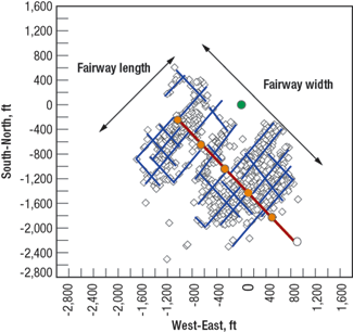 |
Fig. 6. This fracture network area and orientation on a horizontal fracture treatment in an uncemented wellbore has fracture half-lengths of about 1,200 ft, and cumulative fracture segment length of more than 100,000 ft.
|
|
REAL-TIME FRACMAPPING
Barnett operators routinely use real-time microseismic fracture mapping to optimize fracture treatment designs, including adjustments to treatment volume, rate, and perforation locations in subsequent stages. For Barnett wells outside the Core, fracture orientations are rotated and more variable. Fracture mapping is important to minimize the likelihood of connecting into the underlying Ellenburger aquifer. By determining proper wellbore orientation and measuring fracture growth as a function of treatment, design frac rates and volumes can be varied to avoid water-bearing strata.
Microseismic mapping gives operators the information needed to determine the proper number of frac stages, the coverage effectiveness of those stages, the ideal spacing between adjacent laterals, the height coverage (in or out of zone) and an indication of early productivity using proprietary correlations of mapped volume to Barnett production.
The first example shows where an operator adjusted Stage-2 perforation locations from the original plan, based on Stage-1 mapping data, Fig. 7. Stage 1 mapping showed that the frac contacted a significant volume of the reservoir planned for stimulation in Stage 2. The second-stage design was modified based on the unexpected, substantial growth of the first-stage treatment toward the heel of the lateral.
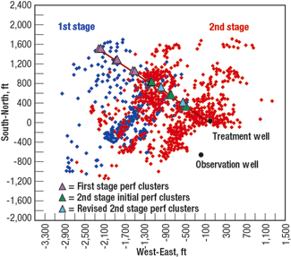 |
Fig. 7. The second stage fracture design was modified based on the growth of the first stage treatment toward the heel of the lateral, seen in this real time mapping operation.
|
|
Second-stage perforations were shifted about 300 ft toward the heel and reduced from three to two clusters from the original design, in an effort to move the second-stage frac away from the area already stimulated. The second-stage re-design was successful, and the entire length of the lateral was stimulated. Operators are also using the real-time mapping technique to keep the fracture out of faulted and karsted areas, by watching and reacting to fracture growth in real-time.
OPENING THE FAIRWAY
The second example is from a multi-month, dual microseismic array that monitored a series of horizontal-well stimulations.3 The original stimulation used a propped, gel treatment in a SW-NE horizontal well. After several poor-productivity months, the operator refraced the well, using conventional waterfracing. Operational problems produced a short injection, which was later followed by the planned flow.
The well was oriented and drilled to produce a longitudinal fracture. The initial treatment used 11,600 bbl of 25-lb, crosslinked gel and 700,000 lb of sand pumped at 70 bpm for three hours. Sand concentrations were ramped up to 3 ppg. The fracture pressure gradient started at 0.61 psi/ft and was increased to 0.71 psi/ft. The “toe” and “heel” regions of the well were covered by monitoring arrays in wells to the southeast and northwest of the well’s azimuth, Fig. 8.
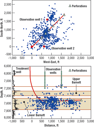 |
Fig. 8. The fracture network opened is about 1,500-ft wide and 3,000-ft long.
|
|
Most of the well was stimulated, although activity around the toe of the well was less than other parts. A large number of microseismic events near the heel-to-center region of the well showed a higher level of activity around three perforated zones closest to the heel. Most of the events suggested that the natural fractures were modestly activated. The longitudinal fracturing stimulated a fracture network less than 500 ft from the wellbore in many parts. The fracturing produced minimal fracture height growth.
Post gel-frac production was less than expected and the operator decided use waterfrac to stimulate the well a second time. After injecting for less than two hours waterfracing was stopped because the equipment could not produce the desired injection rate.
This “failed” refracture treatment looked similar to the initial part of the earlier treatment. Most of the activity was near the wellbore.
A full refract was done the next day. This treatment was pumped at 125 – 130 bpm, tapering to 90 bpm, due to treatment conductor limitations. The injection pumped 60,000 bbl of slickwater and 385,000 lb of sand over 6.5 hr. The initial fracture pressure gradient of 0.7 psi/ft rose to 0.77 psi/ft at the end.
The microseisms recorded outline a much larger area than that affected the earlier gel stimulation. The fracture network opened is about 1,500-ft wide and 3,000-ft long, but is limited near the toe. The treatment apparently broke into the fracture networks of the monitor wells.
Fracture height growth was strong, fracturing into the Barnett limestone above the upper Barnett Shale. Downward growth, into the Viola formation below the lower Barnett also occurred.
The refracturing treatment stimulated a larger rock volume than the initial gel treatment, opening a much wider network of NE and NW trending fractures. The waterfrac stimulated 1,450 million cubic feet of reservoir volume, compared to the 430 million cubic feet opened with the first frac.
Initial production after the gel stimulation dropped from 975 Mcfd to 350 Mcfd after six months. Some interference between the test well and the observation wells can also be seen. Production after the waterfrac re-stimulation had initial rates exceeding 1,500 Mcfd.
CONCLUSIONS
For vertical wells, Barnett hydraulic fractures grow in complex networks, far unlike the simple bi-wing, single-frac geometry encountered in most reservoirs. The total fracture network length controls ultimate gas recovery and the drainage area of a particular well. While primary fracture dimensions can be modeled, overall network development is highly variable from well to well. Fracture mapping demonstrates that a single fracture stage can effectively treat both the Upper and Lower Barnett.
For horizontal wells, the actual location of a perforation cluster does not determine the location of a hydraulic fracture, as the induced fractures clearly interact with, and are affected by, pre-existing natural fractures. Fracing seeks the nearest area of weakness and tends to connect from the perforation cluster to that point from which it then propagates into the reservoir.
Due to stress shadowing effects, often one or two perf clusters work best within a stage, rather than three or more stages where competition between fracture initiation points increases fracture competition and causes increased fracture initiation problems. The nearest perforation cluster in subsequent frac stages should ideally be set apart by a distance equal to 1 to 1.5 times the fracture height. On horizontal wells, we did not see the direct correlation of fracture volume to production as clearly as in vertical well treatments.
Operators are increasing the use of real-time fracture mapping to for real-time decision-making. It helps them stay out of nearby water zones and faults, and helps determine the optimal location for perforation clusters on subsequent frac stages for effective stimulation of the entire lateral length.
Horizontal wells in this study exhibited about two-three times more production during the first 180 days than nearby vertical wells. Uncemented wells were less problematic in placing treatments. At the same time, they appear to have a slight production advantage over cemented completions in this area of the Barnett play. 
LITERATURE CITED
1 Fisher, M.K., and B. M. Davidson, C. A Wright, N. P. Steinsberger, A. K. Goodwin, E. O. Fielder and W. S. Buckler, “Integrating fracture mapping technologies to optimize stimulations in the Barnett Shale,” SPE 77441, presented at the SPE ATCE, San Antonio, Sept. 29 – Oct. 2, 2002.
2 Fisher, M. K., and J. R. Heinze, C. D. Harris, B. M. Davidson, C. A. Wright, and K. P. Dunn, “Optimizing horizontal completion techniques in the Barnett Shale using microseismic fracture mapping,” SPE 90051, presented at the SPE ATCE, Houston, Sept. 26 – 29, 2004.
3 Warpinsk, N.R. and R.C. Kramm, J.R. Heinze, and C.K. Waltman, “Comparison of single- and dual-array microseismic mapping techniques in the Barnett Shale,” SPE 95568, SPE ATCE held in Dallas, Texas, October 9 – 12, 2005.
|
THE AUTHOR
|
 |
Kevin Fisher is president and CEO of Pinnacle Technologies in Houston. He joined Pinnacle in 2000 after 23 years with Halliburton and ProTechnics. Fisher holds seven US patents, and has authored more than three dozen technical papers and articles. He earned a degree in physics from Cameron University and can be reached at Kevin.fisher@pinntech.com.
|
|
|


