Well control during well intervention
WELL CONTROL / INTERVENTIONWell control during well intervention Part 2 – Practical application of through-tubing well control operationsConcentric-tube well servicing systems do not require the use of balance-weight fluids to maintain pressure and flow control; however, when conditions dictate that well pressure be at balance at the surface, well control practices must be employed which focus on fluid hydrostaticsAlex Sas-Jaworsky II, Sas Industries, Inc., Houston
However, when service conditions or job objectives dictate that well pressure be at balance at the surface, well control practices that focus on fluid hydrostatics must be employed. Based on the processes used in conventional jointed-pipe rig systems, coiled tubing (CT) and hydraulic workover (HWO) well control practices performed concentric to existing well tubulars are more complex, and require greater attention in design and implementation.
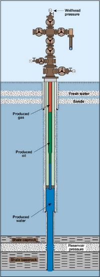
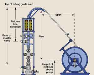
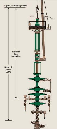
For typical well intervention operations conducted in completed wellbores, the capability to conduct a fluids-pumping, well control program is contingent upon the types of fluids and equipment available onsite. If the initial purpose of the well intervention service is to implement operations in an underbalanced condition, the pumping equipment and fluids available onsite may be inadequate to conduct an effective fluids-pumping kill program, and well control must rely exclusively on the functions of the well control stack. However, for intervention services prepared to conduct a pumped-fluid, well control program, numerous options become available and enhance the safe implementation of this type of operation. Well Intervention / Well Control Practices When preparing for implementing well control programs within stabilized shut-in wells, an estimate of the resident well fluid volume fractions can assist in preparing the fluid circulation / displacement program. In general, the shut-in wellbore will reach equilibrium with the produced fluids stratifying into columns as a function of fluid density, Fig. 5. This condition is in contrast to conventional well control operations where the rheology of the kill fluid is similar to the rheology of the fluid circulated in the wellbore, with the difference in apparent density attributed to the volume of influx fluid. Typically, the return of pressure balance in this condition is achieved by increasing the density of the circulated fluid to the required kill weight and displacing the lighter density volume of influx fluids. However, because of the variable composition of the resident wellbore fluids, the pumping program for well-intervention well control generally will involve two separate fluid circulation processes. The first circulation is typically conducted using an available fluid of a given density prior to pumping the dedicated kill-weight fluid. This "pre-kill" circulation program serves as the means to displace the resident wellbore fluids with a fluid of uniform density and may be either the pumped fluid prescribed for the well intervention service or a specially formulated fluid. The pre-kill fluid displacement process provides valuable information for the design and possible modification of the kill-weight fluids pumping program. After the pre-kill circulation program is completed, the pumping program should be interrupted to allow for static pressure readings to be taken in the wellbore annulus and within the workstring. Note that with pressure check valves installed in the BHA, assistance from the pumps will be required (at the lowest pump rate possible) to open the check valves and allow for pressure communication to the workstring. These static pressure readings are then compared to the predicted pressures at completion of the pre-kill circulation program. Variances observed in this comparison are used to determine the corrective action required prior to commencing the final kill-weight fluid circulation program. The most common fluid circulation-type well control programs used in the oil and gas industry are described as the "Driller’s" method and the "Wait and Weight" method. In essence, these well control practices must be conducted in a manner that maintains a constant bottomhole pressure (CBP) during the fluid circulation program. The CBP practice is intended to provide the desired balance of formation pressure through a combination of hydrostatic pressure created within the wellbore for given fluid columns and the pressure held at surface through a prescribed choke pressure schedule. Using CBP well control practices, the formation pressure is held at, or slightly above, balance pressure during the circulation program, restricting any additional influx of reservoir fluids into the wellbore. The fluid circulation practices employed using the Driller’s method and the Wait and Weight method are described in greater detail below. Driller’s Method The Driller’s method is a fluid circulation practice typically used to displace formation fluid influx from the wellbore annuli. To conduct the Driller’s method properly, the workstring BHA nozzle must be positioned at the designated kill depth. In cases where the circulated fluid density is lower than the required kill-weight density, this pumping program will not result in hydrostatic pressure balance of the well. However, when performed properly, this practice ensures that the fluid in the wellbore is of uniform density upon conclusion. After this circulation stage is completed, the surface pressure is combined with the hydrostatic pressure exerted by the pumped-fluid column, providing a check to confirm the required kill-weight fluid density. The pumping technique employed by the Driller’s method is summarized as described below. Once the BHA nozzle is positioned at the designated kill depth, the stabilized shut-in workstring pressure (SITP) and shut-in annulus pressure (SIAP) are recorded. While maintaining the choke pressure at SIAP, the pump is brought up to the desired pump rate. Once the pump rate is established, circulating pressure (CP) observed at the fluid pump is recorded and serves as the control pressure for this circulation procedure. The circulating pressure is held constant throughout this fluid pumping stage, with adjustments performed at the surface choke. This operation is continued through displacement of at least 1-1/2 annuli volumes or until no formation fluid influx is observed in the surface returns, whichever is greater. Wait and Weight Method The Wait and Weight method is a fluid circulation practice that is intended to achieve hydrostatic pressure balance with the formation pressure through the circulation of one complete wellbore fluid volume. In well intervention applications, the Wait and Weight practice is typically performed as the second circulation of the Driller’s method, where the kill-weight density fluid is pumped to displace the lighter density fluid previously circulated in the wellbore. As with the Driller’s method, the Wait and Weight method is conducted with the BHA nozzle positioned at the designated kill depth. Upon conclusion of this circulation stage, the observed static surface pressure in both the workstring and wellbore annulus should be zero. The pumping technique employed by the Wait and Weight method is summarized below. The BHA nozzle is positioned at the designated kill depth within the wellbore, with stabilized shut-in workstring pressure (SITP) and shut-in annulus pressure (SIAP) recorded. Based on observed SITP, the required kill-weight density fluid is confirmed. The volume of kill-weight density fluid needed to complete the kill operation is prepared and the final stage of the pumping program is initiated. While maintaining the choke pressure at the SIAP observed prior to initiating this step, the pump is brought up to the desired kill rate. Note that pump rate is held constant throughout this pumping technique. With the pump rate established, the pre-kill circulating pressure (PKCP), representing the pressure losses for the system when circulating the lighter-density fluid pumped during the previous circulation step must be recorded. For CT operations, the pumping program must also accommodate a period of pre-kill pump time to allow the kill-weight density fluid to travel through the length of tubing remaining on the service reel to the tubing guide arch. Once the kill-weight density fluid reaches the tubing guide arch (CT) or the circulating swivel (HWO), the pumping pressure is recorded as the initial circulating pressure (ICP). At this point, the kill-weight density fluid begins to displace the vertical workstring segment deployed within the wellbore. As the kill-weight density fluid moves down the workstring segment to the BHA nozzle, the observed pump pressures should decrease with respect to the ICP due to the difference in fluid densities. Once the kill-weight density fluid reaches the BHA nozzle, the frictional pressure losses occurring within the workstring are stabilized and recorded as the final circulating pressure (FCP). At this point, the FCP serves as the controlled minimum pumping pressure for the remainder of the circulation procedure. As the pumping program continues, the kill-weight density fluid is circulated into the wellbore annuli, causing the hydrostatic pressure exerted on the formation to increase. The increase in hydrostatic pressure is compensated by decreasing the surface choke pressure in adjustments corresponding to the kill-weight fluid displacement schedule. This operation is continued for at least one complete annuli volume, or until no contaminated fluid is observed in the surface returns, whichever is greater. The kill-weight fluid pumping program must also take into account the elevation of the tubing guide arch (Fig. 6) or circulating swivel (Fig. 7) with respect to the reference point selected in the wellbore, as well as the difference in elevation with respect to the returns line. The difference in elevation must be considered when determining the effectiveness of the hydrostatic pressure balance in the wellbore when pumping operations are halted.
Onsite Preparation For Well Control Operations When implementing well intervention operations, the following general guidelines are offered to assist in preparation of the well control program.
Coming Installments Part 3 – Well control pumping options to minimize induced formation damage. Part 4 – Proper selection of coiled tubing surface and downhole well control equipment.
|
|||||||||||||||||||||