Well control operations on a multiwell platform blowout
WELL CONTROL / WELL INTERVENTIONWell control operations on a multiwell platform blowoutPart 2 – Relief well designs and drilling operations to intersect / kill platform blowout Wells C and D, offshore IndiaMark Mazzella and David Strickland, Cudd Well Control, a division of Cudd Pressure Control, Inc., Houston
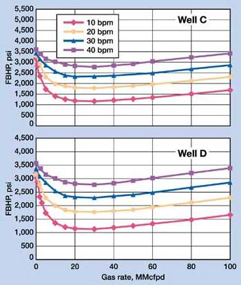
This concluding article describes: 1) the relief well kill design for Wells C and D; 2) the drilling design, including hole geometry and casing program; 3) actual operations for drilling, intersecting, killing and abandoning Wells C and D; and 4) use of two separate jackups in the project to optimize the operation. Relief Well Kill Design Design of a relief well has to start with design of the required kill operation. The required relief well geometry depends on required pump rates to kill the well. The casing program must take into account the anticipated worst-case pump pressures. Although relief well kills are typically achieved through U-tube losses of drilling mud from the relief well entering the blowout well, this cannot be solely depended on. A more definitive kill method must be designed. Two of the most common methods are dynamic and overbalance kills. Both of these methods are similar in operation and design. A dynamic kill uses an initial kill fluid with a density less than that required to statically control the well. The kill is accomplished with a combination of hydrostatic pressure exerted by the kill fluid and the frictional pressure component associated with the fluid moving up the blowout well. This combination generates a bottomhole pressure greater than the reservoir pressure and thus kills the well. A heavier killweight fluid is then circulated to enable the well to be killed statically. An overbalanced kill uses a kill-weight fluid that equals or exceeds equivalent mud weight of the reservoir pressure. The hydrostatic pressure exerted by the kill-weight fluid alone kills the well. Kill rate is determined through multiphase-flow modeling of the blowout well, and is the rate at which the blowout well cannot carry the fluid out of the wellbore and essentially loads up with liquids. In both methods, kill rates are determined to estimate hydraulic horsepower requirements. Actual kill rates are adjusted during the operation based on monitored BHP. Relief wells must be designed to take into account possible drilling problems. If shallow gas is encountered in upper hole sections, or other drilling problems arise, it may become necessary to set an additional casing string. The relief well design must take this possibility into account. The intersect plan would attempt a direct intersect of the blowout well by the relief well. If direct communication could not be obtained, contingency plans would be designed to perform acid jobs and/or attempt to perforate between the two wells. Both of these methods should improve the communication. An overbalanced kill method was selected for the project. This would require less hydraulic horsepower than a dynamic kill performed with saltwater. Fig. 4 shows multiphase flow analysis results for Wells C and D, respectively. Both Wells C and D would require kill rates of 40 bpm. These analyses were performed with a worst-case analysis of a blowout conduit of the tubing string and the tubing x casing annulus. Pump pressures in the relief wells were estimated to be 2,500 psi, giving a required 2,450 hhp. A 100% backup was recommended, resulting in an overall 5,000 hhp requirement.
Relief well surface location. Fig. 5 shows positions of the two relief well rigs and the platform. The surface location of the relief wells was based on the following criteria.
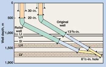
Also considered were the directional path of Wells C and D, and the optimal directional plan for relief wells to intersect blowout wells. Kill support vessel. Initially, the ONGC stimulation vessel, Samudra Nidhi, was to be used to perform the kill operation. Later, the vessel’s DP system was evaluated and it was determined that it could not hold its position connected to the relief well rig for the required time. Besides this DP requirement, a kill vessel with the required horsepower and mud storage would be needed. A vessel was located which could store up to 3,700 bbl of 18-ppg mud. Six pump units would be placed on the top deck to provide 5,000 hhp. The vessel was mobilized from Singapore to Abu Dhabi to be fitted with the pump equipment and then to the B-121 platform area to be loaded with kill mud. Relief Well Drilling Design A relief well drilling team comprised company, well-control and directional-company personnel. Major design points are discussed below. Hole geometry / casing seat selection. Hole geometry used to drill the original B-121 wellbores was sufficient for the relief well wellbore geometry. Mudline suspension (MLS) hangers would be utilized to support the expendable nature of the relief wells. Casing points were selected deeper than used in the original wellbores. Fig. 6 shows original well casing seats vs. those in the relief well. The main reasons to deepen the casing points were: 1) limit amount of open hole below last casing shoe for kill operations; 2) eliminate possible lost circulation problems; and 3) achieve higher casing shoe integrity.
Drilling / ranging plan. The planned directional operation limited dogleg severity to 3 – 4.5°/100 ft. The directional plan for both wells would allow the well to be within 30 – 50 m of the blowout well in the 17-1/2-in. hole section. This would allow the blowout well to be identified by magnetic proximity logging tools. The 13-3/8-in. casing would not be set until proximity tools located the blowout well. Once this string was set, the relief well would be drilled toward the blowout well and attempt to become nearly parallel (1 – 5° angle of incidence) and below the blowout well during the 12-1/4-in. hole section. The relief well would be lined up with the blowout well and within 1-m horizontal displacement before the 9-5/8-in. casing was set. The 8-1/2-in. hole section would then be drilled to intersection. Preliminary plans looked at the feasibility of drilling Well C and D blowout relief wells from a single location. This could be accomplished by either sidetracking the well after the first well was intercepted or by using a second wellbore from the same surface location – both of these methods were feasible. A decision was made by ONGC to drill two separate relief wells simultaneously. This was done in an attempt to get both wells drilled and abandoned prior to onset of the monsoon season. Drilling two wells from a single location would cause the rig to be on location during monsoon season. The actual directional plan for both relief wells would be adjusted and continually modified once the blowout wells were identified by magnetic proximity logging. The frequency of running the proximity tool would depend on quality of data received by the tool and consistency / quality of blowout well surveys. Casing design. For the relief wells, designs were based on casing sizes, grades and weights available at ONGC’s supply yard. A check of casing designs used on the platform wells showed that the design was sufficient for relief drilling requirements. Premium connections would have been preferred for the 9-5/8-in. casing string, but only buttress threads / couplings were available. Relief well operations organization. Well operations were organized to ensure optimal communication between rig, oil company management and support organizations. Regular morning meetings were held to monitor well operations. Well C’s relief well was spudded prior to Well D. Due to the Well C relief being the lead drilling project, operations were centered on the Kedarnath jackup. A senior well-control specialist was posted on each drilling rig. A senior well-control engineer and relief well drilling coordinator split time between the two locations. Morning meetings were held on each of the rigs. Weekly meetings were held at the relief wells with the office drilling staff. Relief Well CR Drilling Operations This well was drilled by the GESCO Kedarnath jackup and targeted the Well C blowout well. The drilling stage of the CR relief well is summarized below. Rig mobilization, 30-in. drive pipe/26-in. surface hole. Kedarnath was mobilized to the relief well location. The rig was preloaded and readied to drill. The location’s water depth was 75 m (246 ft). The jackup was prepared with an 18.3-m (60-ft) air gap to be able to withstand the Western India monsoon season, if required. RKB height was 32.3 m (106 ft) above mean sea level; 30-in. drive pipe was driven to the point of refusal at 177 m. The 26-in. hole was drilled to a TD of 503.8 m on April 12; 20-in., 133 ppf, X-56 casing was run. The 20 in. was cemented to surface. 17-1/2-in. intermediate hole section. A 21-1/4-in. Hydril annular BOP/diverter arrangement was used in drilling the 17-1/2-in. hole. A leakoff test was performed after drilling 3 m of new formation; a LOT of 13.5 ppg was determined for the 20-in. casing shoe. After the LOT, the drilling assembly was tripped and a gyro survey run. Directional drilling started at this depth and continued to 1,255 m on April 22. The hole was prepared for the first proximity-tool logging run. Prior to logging, the well was circulated and had 3% to 14% gas on bottoms up – log results are shown in Table 2. The blowout well was located with the proximity tool logging run.
After logging for proper formation correlation, the well was prepared for the 13-3/8-in. casing, and the 68-ppf, N-80 grade string was tripped in and cemented. 12-1/4-in. intermediate hole section. A 13-5/8-in., 10,000-psi, three-ram stack was used while drilling the 12-1/4-in. hole. The BOP stack was nippled up and tested to 250-psi low and 4,500-psi high (all well-control equipment was tested at this time). The float equipment, cement and 6 m of new hole to 1,259 m were drilled. The LOT was performed and a frac gradient of 13.5 ppg was confirmed at the 13-3/8-in. shoe. The drillstring was pulled so gyro and CBL-VDL surveys could be performed. The latter showed good quality cement bond to the pipe and formation. Directional drilling continued to 1,368 m on April 29. The hole was conditioned for logging and the drillstring was pulled. The second proximity survey was performed, see Table 2. Directional drilling and proximity logging continued over the next two weeks. Significant gas was seen on each bottoms-up during circulation. Previous wells drilled in this area did not encounter any gas in this hole section. Seven proximity surveys were run between 1,368 and 2,018 m, Table 2. The relief well directional plan was adjusted after each survey to maintain the correct intersection projection. Through directional drilling, the relief well continued to be drilled toward the blowout well and position itself near parallel to the well. The relief well reached the casing setting depth of the 9-5/8-in. string of 2,019 m on May 13. At this position, the relief well was less than 1 m from the blowout well and almost directly under it. A gyro survey and open hole logs were run at this depth to confirm bottomhole position of the relief well and that the well was below the VL subsidiary limestone. The 9-5/8-in., 47-ppf, N-80 casing was then run and cemented. A CBL-VDL log run after cementing showed good quality casing and formation bond behind the string. Relief Well CR Killing / Abandonment For the 8-1/2-in. intersection hole section drilling, the magnetic ranging tool survey run at 9-5/8-in. casing depth showed that the blowout well was located 0.9 m (± 0.25 m) from the relief well. An updated directional plan was prepared to attempt to intersect the well at 2,039 m in the relief well. This would place the intersect point below the production packer and above the top perforation in Well C. To achieve this intersect, the relief well would be drilled with a directional BHA and bit until sufficient contact with the blowout well was obtained. After this was accomplished, the drillstring would be tripped and a BHA comprising the mill would be tripped back into the hole. Milling would be initiated at 6:00 hr to attempt to make the intersection during daylight hours. Drilling to the initial intersect point progressed with only minimal signs of contact with the blowout well casing string. Magnetic ranging tool survey results and projected blowout well and relief well paths were reexamined. Eclipses of uncertainty were generated for each well path, and other possible intersection points were predicted. Drilling continued to these intersection points in an attempt to contact the blowout well string. No positive signs of contact were observed. The decision was made to continue drilling the relief well and attempt an intersection at the depth of the perforations. An updated plan was developed and drilling continued to the depth of the perforations with no problems. No losses were observed in the relief well until a depth of 2,057 m. This depth corresponded to the mid-perforation depth in the blowout well. Drilling losses were at a marginal rate of 1 – 2 bpm. Within seconds of the first sign of drilling losses, white smoke (steam) was observed coming off the platform. The decision was made to continue the drilling to increase communication between relief and blowout wells; losses increased to 5 – 6 bpm and steam from the platform ceased at this time. Drilling continued to the bottom of the blowout well perforations. Only minimal losses were observed during this drilling activity, indicating communication with the blowout well had been lost. The fire from the platform had only been reduced a marginal amount. This fire would change direction and apparent intensity depending on the direction / strength of the wind. The change to the platform conditions could not be verified at the time of the kill operation. First acid job. The decision was made to attempt a matrix acid job to increase communication between the two wells. Sixty bbl of 15% HCl was prepared. This was circulated to the bit and displaced with 120 bbl seawater. Before the acid could be overdisplaced, returns were lost and communication with the blowout well was reestablished. The acid job was followed by 10.5-ppg mud. Pump pressure increased to an equivalent mud weight of 13.5 ppg on the formation. This was significantly higher than the required pump pressure and the operation was halted. Communication with the blowout well was once again lost. Fracture gradients in offset wells and the blowout well had been recorded as 13.5 ppg. The high frac gradient recorded at the 9-5/8-in. shoe of the relief well was believed to be affected by the cement job and not an accurate measurement. When pump pressure climbed – causing an equivalent mud weight in excess of 13.5 ppg to be placed on the relief well – the operation was halted to avoid fracturing the formation. Well C kill. The following day, an overflight of the platform confirmed that Well C flow was in fact stopped. Clear views of the well showed no signs of flow. There appeared to be some dehydrated drilling mud around Well C’s wellhead area. Communication between the two wells was still not present. An openhole leakoff test was performed to evaluate the LV limestone formation and a fracture gradient of 15.8 ppg was determined. Communication had to be reestablished between relief and blowout wells before the blowout well could be plugged. Three different plans were developed. The first option was to attempt to mill a hole in the casing above the perforations. The magnetic ranging tool survey performed after the kill operations showed that the two wells did contact each other at 2,023 to 2,226 m. This contact was confirmed by the gyrodata survey. The second option would be to attempt to perforate the blowout well casing at the depth described above. The third option was to attempt a second acid job. Second attempt at casing intersect. The casing mill was tripped, and only marginal losses were observed during this operation. The mill could never obtain a suitable seat against the blowout well casing string. The 9-5/8-in. casing was set 3 m off bottom of the 12-1/2-in. hole section; this resulted in a large hole size at the position of the motor during the initial intersection point. This large hole size did not allow the bit to be pushed against the casing wall of the blowout well and allowed the bit to skip off the blowout well casing. Small quantities of metal shavings were circulated to surface and caught in the magnets in the return line; however, the milling job was unsuccessful. Tubing conveyed perforating. The decision was made to attempt to perforate the blowout well casing string with tubing-conveyed perforating. The drillstring was tripped and the TCP assembly was prepared. The gun assembly was tripped and positioned at 2,023 – 2,026 m. A correlation run was performed with wireline, and the gun was positioned and oriented at the desired depth. The pressure-activated firing sequence was performed and the gun fired. No increase in communication was observed after firing the guns. A decision was made to trip out the TCP gun assembly and confirm that the guns had fired. If they had not fired, then a second attempt may have been performed; a second acid job would be attempted if the guns had fired. Once the guns were tripped out, it was confirmed that they had fired successfully. Second acid job. A second acid job was designed to be circulated down the drill pipe, then pumped into the formation at 100 – 200 psi above static shut-in pressure. Forty-five bbl of 15% HCl was prepared. The acid was circulated to the bit, and 5 bbl were circulated around the drillstring. The annulus was shut-in and the acid was slowly squeezed from the relief well wellbore. After 30 bbl were squeezed, pump pressure broke back and injection rate was increased. An injection rate of 9 bpm was achieved and communication between relief and blowout wells was reestablished. A stream of discolored water was seen downsteam of the platform. A helicopter flight over the platform revealed mud coming from Well C, flowing from what appeared to be the flange connection between the B and C sections of the wellhead. Bottom cement plug. After final preparations for the cement abandonment plug were completed, a final cement plan was developed. The 150-bbl of cement was displaced into relief and blowout wellbores. With 14 bbl remaining, the annulus of the relief well was shut-in and 14 bbl was squeezed into Well C. After allowing the cement to set, the relief well was circulated with 10.5-ppg mud. The B-121 CR relief well was then plugged while pulling out of the hole. Analysis of Well C kill operations. The relief well kill design was based on Well C flowing up the 3-1/2-in. production tubing and the 3-1/2-in. tubing x casing annulus. This was considered the most likely, worst-case scenario. The existence of casing flow from at least one well was apparent from the earlier flow from the other wells on the platform. Well C was killed at a much lower rate than determined using the above assumption. Multiphase flow analysis was performed on the well with flow only up the tubing string. From this analysis, a kill rate of 3 – 5 bpm is required with 10.5-ppg mud. This rate is equivalent to the loss rate observed in the relief well. Thus, flow from Well C was tubular flow at the time of the kill operation. Relief Well DR Drilling Operations For rig mobilization, 30-in. drive pipe, and 20-in. surface hole, the Pride Pennsylvania jackup drilled the Well D relief well. Driving of 30-in. conductor was started, and continued to refusal at 300 spf, at a depth of 184.4 m RKB. The flange adapter was welded onto the 30-in. conductor, and the 30-in. diverter was nippled up and tested. A 30-in. diverter with 11-in. diverter lines was used in the 26-in. surface hole section. The diverter was rigged up and function tested prior to drilling operations. The 26-in. hole BHA was made up and run. A gyro survey was run at the bottomhole location of the 30-in. diverter. Directional drilling started below the 30-in. conductor with a 26-in. drilling assembly, to a depth of 248 m. A 17-1/2-in. drilling assembly was used to directionally drill from this point to the 20-in. casing shoe depth of 507 m on April 19. The hole was then underreamed with a 26-in. hole opener to a depth of 503 m. The 20-in., 133-ppf, X-56 casing was prepared, run and cemented. The diverter was nippled down and the 20-in. was prepared for the A section of the wellhead, which was welded on the 20-in. casing. 17-1/2-in. intermediate hole section. A 21-1/4-in. diverter system was used while drilling the 17-1/2-in. intermediate hole section. The diverter was rigged up and function tested prior to drilling operations. The casing shoe and 2 m of new formation were drilled to a depth of 509 m. A LOT was performed and a frac gradient of 13.5 ppg was determined for the 20-in. shoe. Directional drilling continued from this depth to 1,260 m. The hole was prepared for the first proximity logging survey; the tool was unable to locate Well D. Directional surveys of Well D and the relief well were re-examined, taking into account the shifts in surveys observed in Well C and CR. A new directional plan for Well DR was developed. The 17-1/2-in. hole was drilled to 1,380 m. The hole was once again prepared for proximity logging. The blowout well was located during the second run, Table 3. Well D was found to be shifted 2.4 m south and 16.58 m east of its original, projected location.
After the second proximity log located Well D’s wellbore, the DR wellbore was prepared for running 13-3/8 in. The 68-ppf, N-80 casing was prepared; the 21-1/4-in. diverter was nippled down and the B section of the wellhead was nippled up. 12-1/4-in. intermediate hole section. A 13-3/8-in., 10,000-psi, 3-ram BOP stack was used on the 12-1/4-in. hole section. The BOP was nippled up and tested to 250-psi low and 4,500-psi high. Cased-hole cement evaluation logs were run while nippling up the BOP. The CBL-VDL showed excellent casing-cement and cement-formation bond. A 12-1/4-in. BHA was made up and run. The casing was tested to 3,000 psi. Two meters of new formation were drilled, and a LOT showed a frac gradient of 15.8 ppg at the 13-3/8-in. shoe. This shoe test was much higher than the shoe test observed in Well CR. Directional and proximity logging continued to a depth of 2,211 m on May 27. Eight proximity surveys were taken in the 12-1/4-in. hole section. Well DR Killing / Abandonment For drilling the 8-1/2-in. intersection hole section, the magnetic ranging survey performed after drilling out the 9-5/8-in. casing shoe showed the blowout well to have 0.59 m (± 0.1 m) horizontal displacement. An updated projection of the blowout well and updated directional plan for the relief well planned for an intersection at 2,233 m MD in the relief well. This depth was below the production packer and above the perforations in Well D’s wellbore. The same type of intersect plan was developed for Well D as was used for Well C. A directional BHA with bit would be used to drill to the intersect. At this point, the drillstring would be tripped and a mill run. Milling would be initiated at night to ensure that the mill would be able to seat against the blowout well casing. After positive contact with the casing was confirmed and a good seat for milling was established, the operation would be suspended until daylight. As in Well CR, if the casing could not be milled, then the relief well would be drilled to the depth of the blowout well’s perforations. The relief well tagged the blowout well at 23:30 hr on June 5. The milling operation was initiated to see if a good contact could be established. After less than an hour of milling, losses at a rate of 10 bpd were observed. White smoke was seen on the platform almost immediately; no discolored water could be seen. The fire on the platform was obviously reduced. All personnel were alerted and placed in position for the kill operation. Milling continued and losses stabilized at 10 bpm. The drillstring was picked up; losses immediately increased to 20 bpd; and the fire on the platform started to exhibit slug-flow-type characteristics. The decision was made to bring kill-vessel pumps online; this would ensure that an adequate kill rate could be obtained. After a short time online with the pumps, the well stopped exhibiting slug-type behavior – the relief well was circulating up the blowout well. Kill vessel pump rate was adjusted to 12 bpm and a pump pressure of 1,400 psi. After the kill vessel had pumped a total of a complete well-to-well volume, the platform was inspected via an MSV. Mud was observed coming out of Well D; all other wells appeared to be stable. The mud was coming from the B and C section flanged connection. Bottom cement plug. A total 170 bbl of cement was pumped down the relief well. This resulted in 50 bbl of cement being placed in Well D’s wellbore; an additional 30 bbl of cement was squeezed into the wellbore. The cement was allowed to set and the drill pipe was circulated with mud. The platform was inspected by air and MSVs, and all wells appeared to be static. Analysis of the operation. The kill operation of Well D was achieved by milling or punching a hole in the well’s casing string. The mill was retrieved after the job, and one of the ears had been broken off. A high-quality circulation path was present between Well D and DR wellbores. During the kill operation, when mud losses were in the 10 – 12-bpm range, the well appeared to be flowing in slug flow regime, flowing gas and mud slugs at regular intervals. When rates increased to the 20-bpm range, all gas flow ended and the well was killed. The kill vessel was then able to circulate 12.5-ppg mud from the relief well into Well D. The kill rate required to kill Well D was less than determined for flow up the tubing and tubing x casing annulus. Multiphase flow modeling was performed for flow up the tubing x casing string only. This analysis determined a kill rate requirement between 15 and 20 bpm for the expected pore pressures – this corresponds well to the actual kill operation. From this analysis, Well D was flowing up the tubing 3 casing annulus. Platform Abandonment Project With the well-control event on the platform controlled from relief wells, the platform, the remaining wells and the upper portion of the blowout wells needed to be plugged and abandoned properly. This work was commenced in early 2000, after the 1999 monsoon season – these operations were still ongoing in late 2000. A large crater was discovered under the platform. The tubing of Well D was determined to have dropped 30 m. This would place the packer below the LV formation perforations. If this were the case, flow from Well D was annular, as suggested by the well kill operations. Conclusion The B-121 platform well control incident required surface and subsurface (relief well) intervention efforts. The surface intervention effort was successful in demobilizing the Sagar Ratna jackup rig with only minor damage. The relief well effort was successful in controlling
the blowouts. Careful planning and teamwork between operator, well-control company, directional company,
drilling contractor and other service companies was critical to success of a project of this magnitude. The
entire program was performed in a safe manner with no incidents during the 87 days of the operation.
Acknowledgment The authors extend their appreciation to Oil and Natural Gas Corp. and Cudd Pressure Control, Inc., for permission to publish this paper. Numerous other personnel, international governmental agencies and service companies contributed to the success of this project, unfortunately there are too many to list. This article was prepared from a paper presented by the authors at the IADC International Well Control Conference, Dec. 6, 2000, Houston, Texas.
|
||||||||||||||||||||||||||||||||||||||||||||||||||||||||||||||||||||||||||||||||||||||||||||||||||||||||||||||||||||||||||||||||||||||||||||||||||||||||||||||||||||||||||||||||||||||||||||||||||||||||||