Technology at Work: Unique chemical cutter test fixture
TECHNOLOGY AT WORKUnique chemical cutter test fixturePatrick C. Hyde, Hyde Engineering, Hurst, Texas; and Monty Harris, President, Harris Tool & Specialty, Inc., Azle, Texas
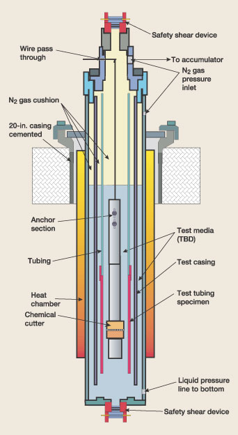
The test fixture shown in Fig. 1 is the evolution of years of experience with different types and sizes of cutters and tubulars, as well as a myriad of wellbore fluids, pressures and temperatures. Advantages and use of the test fixture are presented here, along with results of two case history applications.
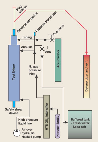
Objectives, test approach. The ideal situation is to perform a cut in an actual wellbore, using volume effects of the relatively large (compared to a test fixture) axial capacity, both above and below the cutter. The first hurdle is to design a fixture that will simulate volume both above and below. The second obstacle is the firing of an explosive in a closed vessel of relatively small volume, under pressure and temperature. The final obstacle is to accomplish a technically realistic simulation both safely and economically. The most straightforward method of simulating well volume in a test fixture is to employ a nitrogen (N2) gas cushion. This approach was used in early testing, in which fluid levels were dropped about 6 ft and the top of the fixture was filled with N2. In a simple fixture design, this provides a cushion on top of the fixture, but provides no cushion from below. While this simulation is realistic when cutting on top of a plug, or close to TD, it does not represent firing a cutter at some distance from an obstruction. Early testing also resulted in abnormally high vessel pressure, accompanied by the occasional venting of high-pressure gas at the time of the cut. To understand why it is necessary to go to some length to simulate volume below the cutter, it is necessary to understand one of the primary requirements of a good cut; i.e., the cutter must remain stable (not move) in the axial direction during the cut. To accomplish this objective, cutter designs feature some method of anchoring the severing head inside the tubular to be cut. That method usually employs round anchor buttons with wickers, located above the severing head and activated by increased internal pressure of the reacting chemicals. The anchors must extend and "grip" the tubular before energy is expended at the severing head. When the cutter operates, high-pressure gas exits the severing head nozzle. If there is an obstruction close and below the cutter head, pressure waves return rapidly to the bottom of the tool, tending to lift the cutter head, thus placing axial loads on the tool (and the anchor system) that are considerably greater than those expected in wellbore operation. The return time of these waves is also considerably less (less distance traveled) than in actual operation. Fixture design features. Design and fabrication of the cut fixture features an N2 cushion both above and below the cutter to simulate "wellbore volume" in both places. The cushion above is obviously provided by the N2 cushion in the tubing above the cutter. The cushion from below is accomplished by an additional concentric tubular with N2 in the annular area between the tubular to be cut and the outer vessel housing. The 6-ft N2 column in the tubing cushions fluid above the cutter, and fluid below the cutter is cushioned by another 6-ft N2 column in this annular area. The two columns can be isolated or connected; the effect is the same. When activating an explosive in a closed chamber, a method of safely controlling maximum vessel pressure must be devised. Should a device malfunction or simply liberate an amount of high-pressure gas sufficient to damage the fixture (exceed its internal pressure rating), a relief system must be employed. The fixture employs independent shear type relief devices that trigger at » 11,200 psi both on top of the fixture and in the bottom plug. Since cutters are generally run toward the bottom of the fixture, abnormal events often generate pressure waves that can damage the fixture on bottom before they lift the column of heavy fluid and activate the upper shear-type relief; hence, the bottom plug shear device. Situations have been experienced in which the lower shear device was activated with the top completely removed from the fixture. Both devices are identical in design and open a 3/4-in. hole to "atmosphere." The lower device opens a port to the bottom of the well and the upper device opens a port to a 2-in., 15,000-psi-rated flowback system with de-energizer. These devices open the upper and lower ends of the tubing to atmosphere, should tubing pressure approach rated vessel pressure. An optional Autoclave Engineers burst disk mounted in a 1/4-in. connection can be installed in the upper annulus to relieve gas pressure. Testing proved that the upper and lower cushion design is effective in simulating volume, but some cutters increased internal vessel pressure in excess of 2,000 psi when fired. Since this condition would likely not be present in wellbore operation, it was obvious the cushion had to be larger on both sides. Cutters are sensitive to external pressure, and increased external pressure during a cut would prove to be detrimental and would definitely skew test results. Vessel internal volume could be increased to provide the extra cushion necessary, but that would require a long and expensive fixture as well as a large volume of high-pressure N2 each time a cut is made. To reduce cost / time to increase pressure, a high-pressure test chamber (22,000-psi WP) was converted to an accumulator for use in cut tests. The accumulator is dressed with a 1-in. x 2-in. plug valve and 1-in. hose to the vessel’s tubing and annulus chambers. The manifold system used in cut testing is shown in Fig. 2.
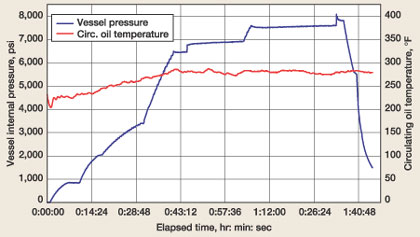
The accumulator can be pre-charged with high-pressure N2. Pre-charging also reduces time to reach test pressure, as only fixture pressure must be increased from ambient. Just prior to firing the cutter, the plug valve is opened, introducing the added accumulator volume to the circuit. When the tool is fired, gas is exchanged between fixture and accumulator. This cushions internal gas pressure in the fixture by effectively increasing fixture total volume. Prior to normal pressure release, the plug valve is closed. Since high-pressure gas is trapped in the accumulator after a cut, it need not be pressurized for subsequent cuts, saving time and N2 expense. Should there be a problem with the N2 pressurizing equipment, vessel pressure can be increased by introducing high-pressure liquid through a line installed in the bottom of the fixture. Results. Using this cut test fixture, vessel pressure increase has been limited to a few hundred psi when the cutter is fired. Cuts have been more uniform, and cutting tools are retrieved in excellent condition. The pressure chart illustrates a chemical cut at temperature and pressure. The example pressure chart is for high-chrome, heavy-wall 4-1/2-in. tubing inside 9-5/8-in. casing, Fig. 3.
In the first of two example case histories, British Borneo Exploration, in the process of re-completing a deepwater subsea well in the Gulf of Mexico, required a reliable tubing cutter to function under conditions of 9,000 psi at 150°F in CaBr fluid. Tubing to be cut was 3-1/2-in., 13 Chrome material. Operating a chemical cutter at this elevated pressure has a prominent effect on performance. Pressure generated by the chemical mix must overcome pressure outside the cutter, in addition to the pressure required for an effective cut. Using a conventional tubing cut fixture would result in a vessel’s considerable pressure increase over hydrostatic, resulting in inaccurate test data. Use of the cut fixture described here resulted in a pressure spike of only 650 psi, declining immediately to a net vessel increase of 67 psi, as a result of produced gases and liberated heat. Shell U.K. required that a 7-in., 29 ppf, SM2535-125
tubular be parted inside 9-5/8-in., 47 ppf casing under 4,200 psi and 265°F, in brine water completion
fluid. The objective was to completely part the tubing without damaging the parent casing. When cutting this
rather-large tubular, vessel pressure spiked only 720 psi, with residual pressure increase of 100 psi as a
result of produced gases and liberated heat. Using a conventional cut fixture, increased vessel pressure would
result in inaccurate test data when evaluating parent casing damage.
|
- Applying ultra-deep LWD resistivity technology successfully in a SAGD operation (May 2019)
- Adoption of wireless intelligent completions advances (May 2019)
- Majors double down as takeaway crunch eases (April 2019)
- What’s new in well logging and formation evaluation (April 2019)
- Qualification of a 20,000-psi subsea BOP: A collaborative approach (February 2019)
- ConocoPhillips’ Greg Leveille sees rapid trajectory of technical advancement continuing (February 2019)

